Abstract
Unilateral external fixation can be used in the provisional or definitive treatment of tibial fractures. A properly applied fixator allows bony and soft tissue stability, whereas an improperly applied fixator achieves neither and can be a hindrance. The principles for the successful application of monolateral external fixation, including the rationale for choosing this type of device, the assembly of its components and deciding on planes of application, are discussed in this article.
Key words: External fixation, Fracture, Tibia, Biomechanics, Stability
Introduction
External fixation has seen resurgence in modern trauma management. Much is linked to damage control strategies as applied to the multiply injured or for the control of soft tissue problems prior to internal fixation [1–4]. Advances in the design of fixators and bone pins have expanded indications — external fixation as definitive fracture treatment is a real alternative for trauma surgeons.
The use of external fixation can be grouped by function:
for temporary or emergency stabilisation of patients with limb- or life-threatening injuries;
as a definitive fracture treatment device;
in limb reconstruction surgery; viz., deformity correction, limb lengthening, treatment of non-unions and osteomyelitis.
Stability with external fixator systems
Many instructional courses on fracture management focus on internal stabilisation, leaving external fixation and non-operative strategies as minor inclusions. Consequently orthopaedic trainees are trained towards proficiency with internal fixation methods, and have only a superficial knowledge of external fixation.
The argument that a provisional spanning external fixator can be applied without due attention to detail is false; if the device is applied for a reason (be it temporary stabilisation for provisional care of the patient or for soft tissue care), then the objective is best met when the fixator is applied correctly. This review of variables that influence fixator stability will assist those wishing to expand their knowledge and experience.
One analogy for the external fixator is that it is an exoskeleton applied in order to support the endoskeleton — the bone which is fractured, deficient or deformed. Manipulations through the exoskeleton produce parallel effects in the endoskeleton. Consequently stability can be conceived as the sum of contributions from both endo- and exoskeletons, and it is here the surgeon is able to adjust the relative contribution from the external fixator towards the total.
The fracture pattern too has important bearings on stability; stresses at the bone-pin interface and ultimately the ability of the fixator to maintain its hold are dependent on the amount of contact and shape of the fracture line [5–7]. This important concept of shared stability introduces a dimension of external fixator adjustments, based on biomechanics, which a clinician is able to harness in order to utilise the device effectively — it can be a far cry from the practice of using a ‘standard’ anteromedial unilateral fixator for all types of tibial fracture.
External fixator biomechanics — altering the contribution of the exoskeleton
The different external fixator systems in clinical use today can be categorised into unilateral or circular types. Bilateral external fixator systems are rarely used now (Fig. 1) although transfixing pins are still used in the os calcis. This review is a focus on unilateral systems for the tibia.
Fig. 1.
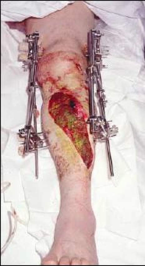
Bilateral external fixation is seldom used as transfixing full pins impede functional use of the limb
Three variables which directly influence the contribution to stability by the external fixator are:
the bone-pin interface,
the components of the fixator;
the fixator configuration (how it is assembled on the inserted bone pins).
The bone-pin interface
This is the crux of stability — starting with a good hold and keeping a good hold of bone.
Two important parameters that influence interface stresses and bone hold are pin diameter and interference.
Larger diameter pins have a higher resistance to bending forces (the cross-sectional moment of inertia of any rod or bar structure increases with the fourth power of its radius). This in turn can reduce the stresses at the bone-pin interface [6]. The limit to increasing pin size is set by the diameter of the bone in which the pin is inserted — a hole exceeding 20% of the diameter of the bone will reduce torsional strength by 34%, and if the hole size is greater than 50% the reduction is 62% [8, 9]. In practice it is advisable to keep pin sizes to within a third of the diameter of the bone to reduce the risk of fracture on removal of the half-pin. Hence general guidelines for pin diameter have evolved and both 5- and 6-mm diameter pins have a place in the tibia and femur.
Interference is a measure of the ‘grip’ the pin has of bone (Fig. 2); traditionally it is at its maximum at the time of pin insertion and may decrease gradually as the fixator is loaded. Therefore maximising interference at the beginning serves to promote bone hold for longer [10, 11]. However this cannot be achieved by simply reducing the size of the pilot drill hole and increasing the major diameter of the pin; such a situation can lead to micro fractures, or crack propagation when the pin is forced into a small pilot hole. As such, manufacturer-led recommendations on drill bit size prior to pin insertion are important if appropriate radial preload is desired. It should be noted that bending pins to create preload is less effective (Fig. 3) and should not be encouraged — radial preload is a more suitable way of increasing interference [12].
Fig. 2.
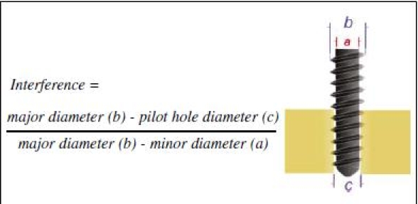
Maximising interference improves ‘grip’; conical screws increase interference as the screw is advanced
Fig. 3.
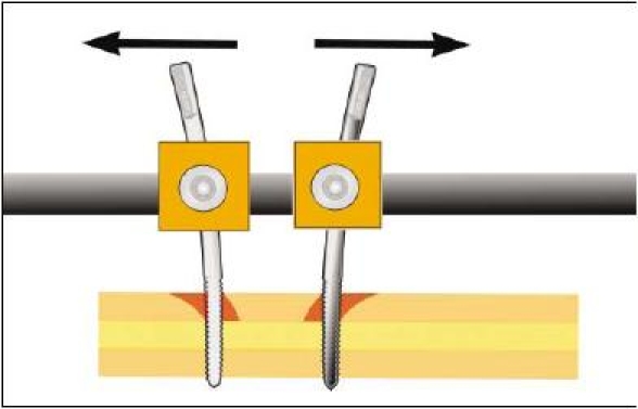
Bending preload-enforced pin separation was thought to improve interference and lessen the risk of loosening; in fact it works less well than radial preload and is not recommended
Manufacturers have also sought to maintain the grip on bone by altering the material properties or surface coatings of the pin. One technology that has shown great promise in comparative studies and proven itself in clinical use is hydroxyapatite coating of the threaded portion of the pin — it is one method by which bone hold increases with time [13–16].
Comparative studies on pin design using pull-out strength measurements are published but the limiting factor in clinical practice is often the shear strength of bone and not screw design. Osteoporotic bone can nullify the effects of advanced screw thread design or metal alloy composition in modern pins. This is because the cantilever loads on pins at the bone-pin interface (especially when the patient is instructed to bear weight in the post-operative period) can produce stresses that exceed the yield strength of cortical bone and lead to resorption and loosening — all this even in the absence of pin site sepsis (Fig. 4). Historically, this explains why many users of external fixators did not allow their patients to walk on their affected limbs but in so doing deprived the fracture site of an important form of stimulation-hence the prejudicial view of external fixation leading to non-unions [7, 8].
Fig. 4.
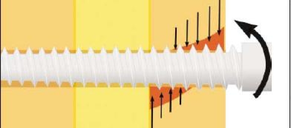
Loads on a fixator during weight bearing are transferred to the pin-bone interface as compressive stresses; if they exceed the yield strength of cortical bone resorption occurs
The components of the fixator
Most unilateral systems exist as one of two types: a construct that is preassembled or comes ready assembled before application (and often incorporates design features that facilitate fracture reduction and dynamisation); and one that is assembled from components after pin insertion. The latter type has gained popularity for it provides the surgeon freedom of choosing pin location and configuring the fixator assembly according to the clinical problem, but this utility of using ‘snap-on’ components and ‘free-style’ assembly has disadvantages — the inexperienced user who is enamoured by this freedom risks applying a fixator that can be inherently unstable.
Fixator components are:
pin clamps which are pin-to-bar connectors;
bar clamps which in turn are bar-to-bar connectors;
connecting bars.
Pin and bar clamps have joints that enable a swivel or universal joint action. Most mainstream manufacturers have engineered these devices to provide ease of application without sacrifice of secure fixation when the clamp is tightened. However it is the responsibility of the surgeon to ensure the clamps are tightened very securely when the fixator has been applied as loose clamps are not infrequently responsible for loss of fracture control. In particular, those clamps that enable multiple pin attachment and are secured by more than one tightening bolt or screw (Fig. 5) have to be tightened by alternating the twists between the bolts — this allows the clamp cover to close over the pins equally and maintain a firm hold. If one bolt is tightened very firmly and the other less so, the clamp cover will rest tilted over the pins and gradually work loose.
Fig. 5.
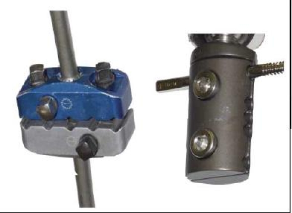
Multiple pin clamps often have more than one screw to secure the clamp cover. These need to be tightened sequentially to ensure the cover descends over the half pins equally and does not tilt
Connecting bars are available in different diameters and of various materials. Whilst stainless steel was previously popular, bars are now commonly made of aluminium alloy or carbon fibre composite. These provide strength (solid bars instead of tubular steel) with the benefit of reduced weight. Even so the diameter of the bar used is important; as previously, stiffness increases with the fourth power of the radius, and as manufacturers provide bars from 8 to 14 mm diameter, the surgeon has to recognise the limitations imposed when using smaller diameter bars. In such cases, double stacking the bars may compensate for the more flexible thinner bars [17] (Fig. 6).
Fig. 6.
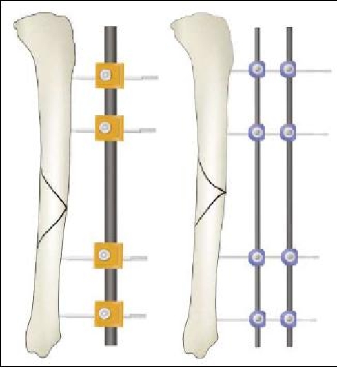
Narrow diameter connecting rods can be stacked to improve bending stiffness in the plane of the half pins but do not increase stability in the orthogonal plane or improve resistance to torsion. Larger diameter rods can be used singly
Fixator configuration
This has a large contribution to the shared stability concept in the exo- and endoskeleton analogy. The manner by which the fixator is assembled can change this contribution through:
the number and spread of pins along the segments, and
the distance between the connecting bar and bone.
Pin number and spread
An increase in stiffness is provided by increasing pin number from two to three in any one segment (the segment being any substantial part created by the fracture — therefore a simple transverse fracture has two segments). The added benefit from increasing pin number from three to four is minimal, therefore three pins per segment is advised [18]. As for pin spread, the ‘near and far’ rule provides a guide; pins should be spread along a segment of bone such that the segment is spanned [18, 19] (Fig. 7). The proximity of any pin to the fracture itself is cautioned as the pin may be within the fracture haematoma and thereby carry the risk of a pin site infection spreading to within the fracture — a rule of thumb of staying at least 2 cm from the nearest fracture line helps. Such application in practical terms should also take into account soft tissue damage and consideration for future plastic surgery, which sometimes limits the options of pin placement.
Fig. 7.
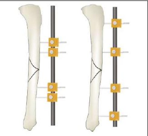
Placing half pins so that they span the segments of the fracture enables better control of displacing forces — the ‘near and far’ rule of thumb
Connecting bar distance
The distance of the connecting bar from bone is determined by the depth of soft tissue in between. Close proximity is possible on the anteromedial surface of the tibia but the reverse is true for the lateral surface of the femur. Bringing the connecting bar closer to bone improves stability and in general it should be kept as close as possible with enough room to facilitate pin site care — 40–50 mm (roughly 2 finger breadths) from the bone surface if feasible [6] (Fig. 8).
Fig. 8.
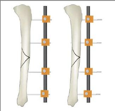
Reducing the connecting bar distance to bone improves stability — two fingerbreadths from the subcutaneous surface of the tibia allows enough room for pin site care
Pin number, pin spread and connecting bar distance can be varied to improved stability. The improved stability reduces the bone-pin interface stresses and helps preserve longevity of stable fixation.
Recognising the contribution of the endoskeleton to stability
It is wrongly assumed the endoskeleton contributes little to the overall stability — this is only true when little contact exists between fracture fragments viz., highly comminuted patterns, bone defects or when the fixator is used in bone transport or lengthening (where the bone ends are purposely separated). In other circumstances there is a shared stability scenario and the amount contributed depends on fragment contact and the fracture pattern. A poorly reduced or comminuted fracture has little contact between fragments and as such weight-bearing forces are almost entirely placed through the external fixator, this creates high bone-pin interface stresses [10]. Oblique patterns will also have the same effect to a lesser degree but, to contrast, a reduced transverse fracture will share a significant portion of load transfer in weight bearing.
Optimising the plane of external fixator application
Fixator half-pins should be inserted in safe corridors (Fig. 9) and the most convenient is the anteromedial (subcutaneous) surface of the tibia. As such most unilateral external fixators tend to be assembled over the anteromedial surface of the tibia. This is appropriate for temporary spanning external fixation, but further attention to the plane of fixator application may yield additional stability if the external fixator is to be used for definitive fracture treatment. Furthermore, even in temporary stabilisation of comminuted or unstable fractures, simple anteromedially applied frames cannot sometimes achieve the degree of stability necessary to offer pain relief and soft tissue control. For this method of optimisation we need to deduce the plane and direction of the injurious force from the fracture pattern.
Fig. 9.
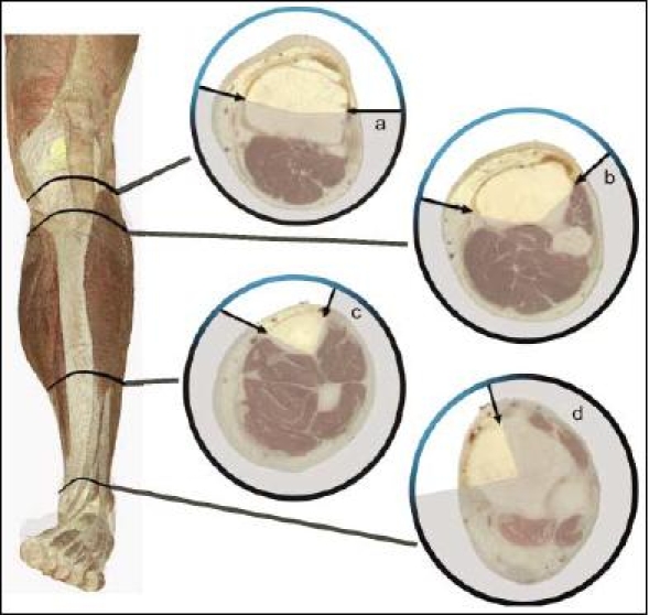
Safe corridors for pin placement in the tibia: (a) this is widest but care must be taken not to transfix the tendons of the pes anserinus on the medial side; (b) the origin of anterior compartment muscles narrow the corridor but a wide area is still present; (c) this is essentially the subcutaneous surface but biplanar pin placement is still possible with forethought; (d) the tibialis anterior tendon can be damaged and should be dissected away if a pin is inserted in the sagittal plane
Fracture patterns tell of the type of force that produced the fracture (Fig. 10). Similarly these forces also produce soft tissue injury patterns. Both fracture and soft tissue injury patterns influence the ability to maintain reduction; there is a tendency for the loss of alignment to be in the same direction as the original displacement. That being so, it is possible to apply a unilateral fixator with due consideration to the likely displacing forces on the fracture:
Transverse fractures are created by tensile forces. If well reduced, these will only demand control of bending and torsion moments by the external fixator as any further shortening is prevented by virtue of a good reduction and the transverse pattern. It has been shown that the major bending forces in the intact tibia during normal walking occur in the sagittal plane [20, 21]. When this information is coupled to the knowledge that any unilateral external fixator has best control of bending moments in the same plane as that of pin insertion, and is weakest in the plane at right angles to this — the ‘orthogonal’ plane [22], it follows that an optimum position for a unilateral external fixator for this type of fracture is in the sagittal plane.
Bending forces create fractures with a butterfly fragment. The apex of the butterfly piece denotes the side of tensile forces and the broad part (base) of the fragment compression — the plane and direction in which the bending force was applied at the time of fracture can therefore be deduced from plain X-rays (Fig. 10). Any displacement after reduction will tend to mimic the position before reduction — this is a reflection of the fracture pattern and soft tissue disruption created by the original force. Control of this displacement can best be achieved by placing the fixator in the plane in which the bending force was originally applied, thereby aligning the plane of control with the plane of displacement. This derivation of the plane of fixator application is simple to work out from the position of the butterfly fragment (Fig. 11a–c). However there are instances when the most appropriate plane is not possible because of the constraints of safe corridors of pin insertion. In such scenarios it is wisest to opt for a biplanar unilateral configuration (Fig. 11d).
Fig. 10.
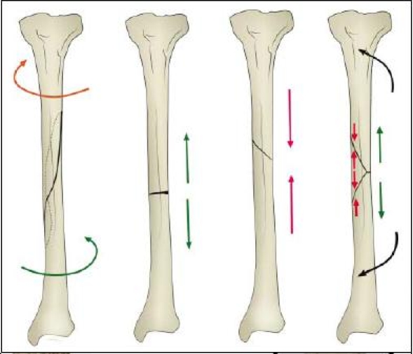
Spiral fractures result from torque, transverse lines are created by tension, oblique lines by compression and butterfly fragments by a combination of tension and compression. Most fractures involve a combination of forces but a dominant mechanism produces typical fracture lines
Fig. 11.
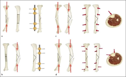
Bending fractures which produce butterfly fragments tend to displace in the direction of the original deforming force. The ‘apex’ of the butterfly denotes the tension side whereas the ‘base’ denotes the compression side. By adjusting the plane of application of the external fixator pins, control of potential displacement can be maximised: (a) Bending forces which produce a butterfly fragment in the coronal plane controlled by a coronal plane fixator. (b) Fracture with a butterfly fragment in the sagittal plane held with a sagittal plane fixator. (c) This fracture produced a butterfly fragment seen in both AP and lateral X-rays — it suggests the bending force was directed from anteromedial to posterolateral, hence the fixator in the anteromedial plane. (d) This fracture was caused by a bending force predominantly in an anterolateral to posteromedial direction — a fixator lying in this plane would breach the safe corridors for pin insertion, therefore a biplanar fixator is appropriate
Biplanar unilateral external fixation
This arrangement of half pins is sometimes referred to as a ‘delta’ frame; the pins remain on one side of the leg but are applied in orthogonal planes. This configuration has particular advantages for control of bending in both sagittal and coronal planes (and in planes in between) as well as high resistance against torsion [17, 23]. The added complexity of this arrangement is worthwhile in comminuted fractures, where there is poor fragment contact, bone defects or where control of torsional forces is needed, e.g., spiral and oblique fractures with an acute fracture plane. It is also helpful for those bending fractures where the most effective application plane is prevented by the absence of safe corridors for pin insertion (see previous section).
Spanning external fixation — some guidelines
The following recommendations apply:
5- or 6-mm pins, inserted in a safe corridor;
at least 2 pins per segment, and if a third is used preferably in a different plane;
the pins adopting the ‘near and far’ arrangement with regard to the fracture site;
a large diameter connecting rod placed within two fingerbreadths of the anteromedial surface of the bone or if narrow diameter ones are used, to be placed in a stacked manner; and
if spanning of proximal or distal third tibial fractures is needed, extending the fixator across the relevant joint is appropriate (Fig. 12).
Fig. 12.
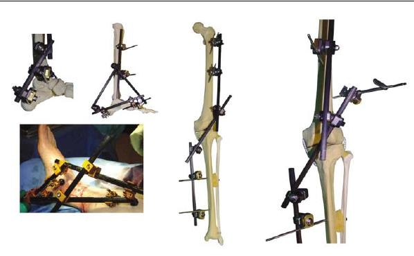
Ankle and knee spanning fixator configurations: in the ankle the os calcis, talar neck and 1st or 5th metatarsals are useful locations for siting pins; for the knee, proximal femoral pins in the sagittal plane are augmented by an additional third pin placed obliquely from the anterolateral side, just proximal to the suprapatellar pouch
Summary
External fixators are versatile tools. They have advantages of percutaneous application and modifiable biomechanical characteristics. This review provides a biomechanical rationale for choosing fixator components, deciding optimum planes of application and configuring fixators in accordance to the injury pattern. Whether used as a device for provisional or definitive management, attention to detail in the choice of pin diameter, plane of application and fixator configuration can make the difference between a patient who can rehabilitate comfortably and stimulate fracture healing through weight bearing and another who is reluctant to use his limb and is faced with early problems of pin loosening and instability.
Acknowledgement
The Authors thank Mr S. Nayagam for the illustrations and for his counsel in writing this article References
References
- 1.Egol K, Tejwani N, Capla E et al (2005) Staged management of high-energy proximal tibia fractures (OTA types 41): the results of a prospective, standardized protocol. J Orthop Trauma 19:448–455 [DOI] [PubMed]
- 2.Harwood PJ, Giannoudis PV, van Griensven M et al (2005) Alterations in the systemic inflammatory response after early total care and damage control procedures for femoral shaft fracture in severely injured patients. J Trauma 58:446–452; discussion 452–454 [DOI] [PubMed]
- 3.Haidukewych G (2002) Temporary external fixation for the management of complex intra- and periarticular fractures of the lower extremity. J Orthop Trauma 16:678–685 [DOI] [PubMed]
- 4.Roberts CS, Pape H-C, Jones AL et al (2005) Damage control orthopaedics. Evolving concepts in the treatment of patients who have sustained orthopaedic trauma. J Bone Joint Surg Am 87:434–449 [PubMed]
- 5.Aro HT, Chao EY (1993) Bone-healing patterns affected by loading, fracture fragment stability, fracture type, and fracture site compression. Clin Orthop Relat Res 293:8–17 [PubMed]
- 6.Huiskes R, Chao EY, Crippen TE (1985) Parametric analyses of pin-bone stresses in external fracture fixation devices. J Orthop Res 3:341–349 [DOI] [PubMed]
- 7.Aro HT, Markel MD, Chao EY (1993) Cortical bone reactions at the interface of external fixation half-pins under different loading conditions. J Trauma 35:776–785 [DOI] [PubMed]
- 8.Hipp JA, Edgerton BC, An KN, Hayes WC (1990) Structural consequences of transcortical holes in long bones loaded in torsion. J Biomech 23:1261–1268 [DOI] [PubMed]
- 9.Edgerton BC, An KN, Morrey BF (1990) Torsional strength reduction due to cortical defects in bone. J Orthop Res 8:851–855 [DOI] [PubMed]
- 10.Pettine KA, Chao EYS, Kelly PJ (1993) Analysis of the external fixator pin-bone interface. Clin Orthop Relat Res 293:18–27 [PubMed]
- 11.Halsey D, Fleming B, Pope MH et al (1992) External fixator pin design. Clin Orthop Relat Res 278:305–312 [PubMed]
- 12.Hyldahl C, Pearson S, Tepic S, Perren SM (1991) Induction and prevention of pin loosening in external fixation: an in vivo study on sheep tibiae. J Orthop Trauma 5:485–492 [DOI] [PubMed]
- 13.Piza G, Caja VL, Gonzalez-Viejo MA, Navarro A (2004) Hydroxyapatite-coated external-fixation pins. The effect on pin loosening and pin-track infection in leg lengthening for short stature. J Bone Joint Surg Br 86:892–897 [DOI] [PubMed]
- 14.Caja VL, Piz G, Navarro A (2003) Hydroxyapatite coating of external fixation pins to decrease axial deformity during tibial lengthening for short stature. J Bone Joint Surg Am 85:1527–1531 [DOI] [PubMed]
- 15.Moroni A, Caja VL, Maltarello MC et al (1997) Biomechanical, scanning electron microscopy, and microhardness analyses of the bone-pin interface in hydroxyapatite coated versus uncoated pins. J Orthop Trauma 11:154–161 [DOI] [PubMed]
- 16.Caja VL, Moroni A (1996) Hydroxyapatite coated external fixation pins: an experimental study. Clin Orthop Relat Res 325:269–275 [DOI] [PubMed]
- 17.Behrens F, Johnson W (1989) Unilateral external fixation meth-20 ods to increase and reduce frame stiffness. Clin Orthop Relat Res 241:48–56 [PubMed]
- 18.Briggs BT, Chao EY (1982) The mechanical performance of the standard Hoffmann-Vidal external fixation apparatus. J Bone Joint Surg Am 64:566–573 [PubMed]
- 19.Huiskes R, Chao E (1986) Guidelines for external fixation frame rigidity and stresses. J Orthop Res 4:68–75 [DOI] [PubMed]
- 20.Behrens F, Searls K (1986) External fixation of the tibia. Basic concepts and prospective evaluation. J Bone Joint Surg Br 68:246–254 [DOI] [PubMed]
- 21.Behrens F, Johnson WD, Koch TW, Kovacevic N (1983) Bending stiffness of unilateral and bilateral fixator frames. Clin Orthop Relat Res 178:103–110 [PubMed]
- 22.Johnson WD, Fischer DA (1983) Skeletal stabilization with a multiplane external fixation device: biomechanical evaluation and finite element model. Clin Orthop Relat Res 180:34–43 [PubMed]
- 23.Egan JM, Shearer JR (1987) Behavior of an external fixation frame incorporating an angular separation of the fixator pins: a finite element approach. Clin Orthop Relat Res 223:265–227 [PubMed]


