Abstract
It is a prerequisite for surgeons using external fixation systems to be familiar with safe corridors for half pin or wire insertion. Several atlases of cross-sectional anatomy are available, mostly in print, to provide guidance [1–3]. This series of articles provides high-quality cross-sectional anatomical images together with guidance in locating safe corridors; the added benefit here is that the information can be downloaded and stored on the surgeon’s or in the operating room computer for ease of reference. This review covers the lower leg from knee joint to foot.
Keywords: External fixators, Tibial fractures, Tibia, Anatomy, Cross-sectional anatomy
Introduction
Identifying levels of cross sections
Safe corridors, as indicated as in an anatomical cross section [1–3], become meaningful only if the surgeon can locate that appropriate level on the limb. One can divide a limb segment into any number of levels and provide corresponding cross sections but this leads to information overload. Fortunately, neurovascular structures follow known paths around the major long bones and changes in position occur at fairly consistent levels, e.g. the common peroneal nerve winds around from posterior to anterior at the level of the neck of fibula. Such changes can be utilised to simplify knowledge of cross-section anatomy for the purpose of half pin or wire insertion. We shall also introduce a method of using surface anatomy together with corresponding cross sections to enable a system of safe corridors that is repeatable across limbs of any size or individuals of any age.
Basic techniques for pin and wire insertion
The following cardinal rules should be observed.
Wire insertion
Ensure the patient is not paralysed in order to obtain feedback from inaccurate wire placement
Pass the wire through muscle/tendon with that muscle stretched fully—transfixation in ‘maximum length’ will facilitate maintenance of function post-operatively
First push the wire through soft tissues down onto bone; choose that side of the safe corridor that is more risky as it is easier for the surgeon to control placement of an entry portal of the wire into the bone than its exit portal
Start the drill with a very short burst in case structures ‘at risk’ are caught with the bayonet tip of the wire
Tap the wire out through soft tissues on the opposite side of the safe corridor, especially if there are ‘at risk’ structures nearby
Half pin insertion
- Choose a diameter appropriate to the bone:
- Tibia (4–6 mm in adults)
- Calcaneum (4–6 mm in adults)
- Metatarsals (3–4 mm in adults)
- Femur (5–6 mm in adults)
- Humerus (4–5 mm in adults)
- Radius and Ulna (3–4 mm in adults)
Wire insertion
- Choose a diameter appropriate to the bone:
- Tibia (1.8–2.0 mm in adults)
- Calcaneum (1.8–2.0 mm in adults)
- Metatarsals (1.8–2.0 mm in adults)
- Femur (1.8–2.0 mm in adults)
- Humerus (1.8–2.0 mm in adults)
- Radius and Ulna (1.5 mm in adults)
- Drill with attention to thermal necrosis
- Use irrigation with stops to clean the drill flutes in hard bone
The lower leg (tibia, fibula and foot)
External fixator use has its highest frequency in this part of the body. Structures at risk are the:
The common peroneal nerve around the neck of the fibula
The deep peroneal nerve within the anterior compartment of the leg, in close proximity to the anterior tibial vessels
The posterior tibial neurovascular bundle which courses close to the posteromedial border of the tibia in the distal third
Useful surface markings are:
Knee joint line
Neck of fibula
Distal metaphyseal flare
Ankle joint line
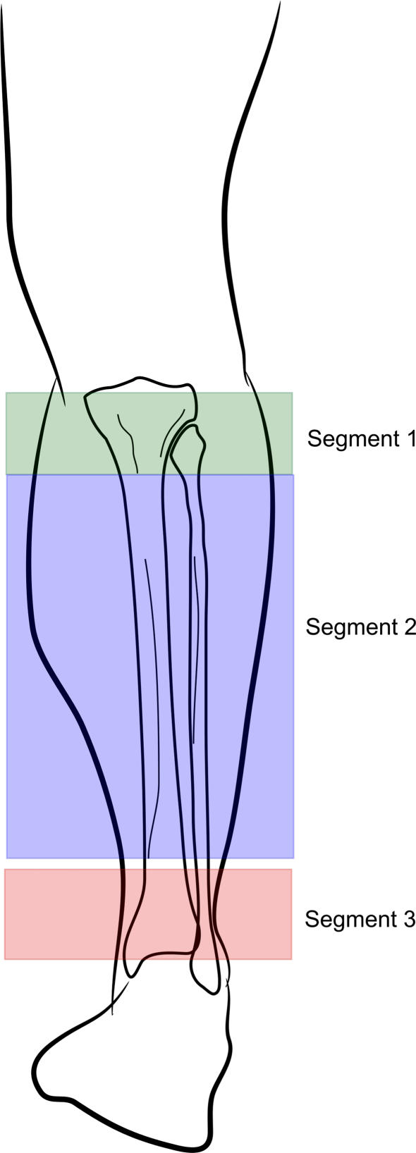
The tibia can conveniently be divided into three segments (Fig. 1):
Knee joint line to the neck of fibula
The neck of fibula to the distal metaphyseal flare
The distal metaphyseal flare to the ankle joint line
The safe corridors within these segments are such that fairly consistent patterns of wire and half pin placement can be used, such that the surgeon would only need to commit relatively few to memory.
Fig. 1.
The three segments of the tibia
Segment 1
This spans the knee joint to the neck of the fibula. Two important anatomical points need to be noted:
The synovium and capsule of the knee joint extends distal to the actual joint line. The limit of this extension is variable and may reach as far as 15 mm below the joint line. Wires inserted proximal to this synovial ‘curtain’ would technically be intra-articular. Often this is not recognised until after surgery when the wire site leaks continually of synovial fluid. These wires are best replaced as there is a risk of local pin site infection becoming a septic arthritis.
The neck of the fibula is the surface landmark for the common peroneal nerve. Transfibular wires at this level must be inserted through the head of the fibula and away from the neck.
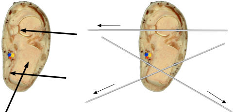
Half pins (bold arrows) have a wide corridor in this segment. They can be inserted across the palpable anterior surface of the tibial plateau, avoiding transfixing the patella tendon.
With the exception of the transfibular wire, there are two main wire corridors for segment 1:
The coronal plane wire
The medial face (so called as it parallels the medial subcutaneous face) wire
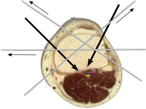
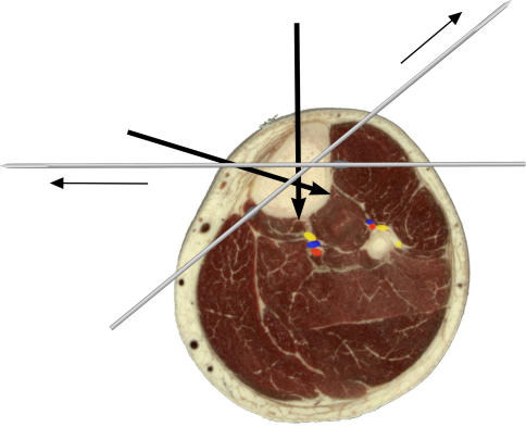
At the most proximal level of segment 1, approximately two fingers’ breadth below the knee joint line, half pins can subtend an angle of 120° in the subchondral area (Fig. 2). The exit portals of these pins are separated from the posterior tibial neurovascular bundle by a slip of deep posterior compartment muscles—avoid over-penetration by either drill or pin.
Fig. 2.
Segment 1: two fingers’ breadth distal to the joint line of the knee
Wires should be inserted at least 15 mm distal to the knee joint line: wires at this level cross at 60°. These wires are the medial face wire and another in the coronal plane. A wire just anterior to the fibula head increases the crossing angle to nearly 90°. Olive wires placed as shown increase stability (Fig. 2).
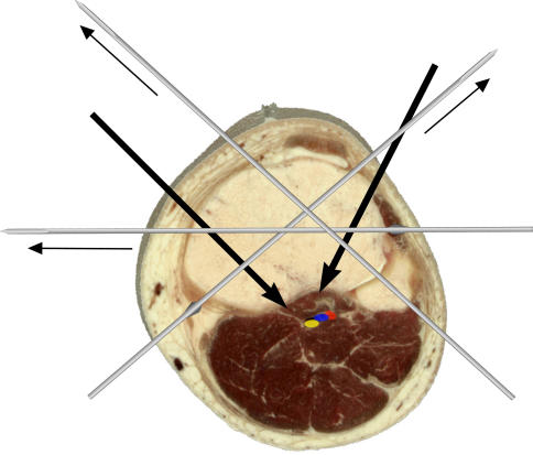
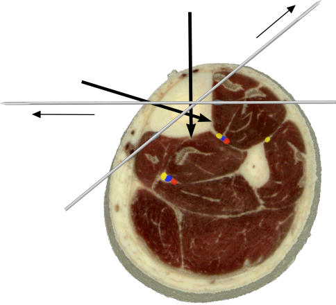
Slightly more distal within segment 1 is the fibula head (Fig. 3). Whilst the half pins are inserted in a similar position to the level above, the angle subtended between the pins narrows as the proximal origin of Tibialis anterior from the lateral surface of the tibia encroaches. The same medial face and coronal plane wire positions can be used as previously (see above), but the addition of a transfibular wire (without olive) will increase the crossing angle substantially.
Fig. 3.
Segment 1: at the level of the fibula head
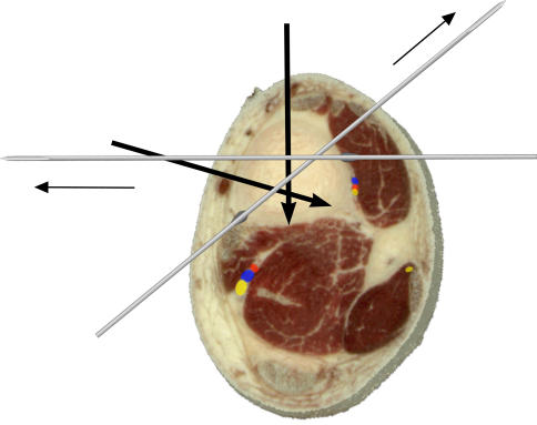
Finally within segment one is the level of the fibula neck (Fig. 4).
Fig. 4.
Segment 1: at the level of the fibula neck
Half pin positions are largely unchanged. Medial face and coronal plane wires are safe. The transfibular wire should be avoided owing to the proximity of the common peroneal nerve.
Segment 2
This spans a region from just distal to the tibial tuberosity to the start of the metaphyseal flare proximal to the ankle joint. The safe corridors for half pins and wires remain largely unchanged through this segment and therefore easy to commit to memory. The posterior tibial neurovascular bundle lies in the plane between the deep posterior compartment muscles (Tibialis posterior, Flexor Hallucis and Flexor digitorum longus) and the more superficial soleus and gastrocnemius muscles. It keeps a midline position until distally when it veers posteromedially. The anterior tibial vessels are with the deep peroneal nerve and remain close to the interosseous membrane on the lateral side of the tibia. Distally this neurovascular bundle migrates more anteriorly, again close to the lateral surface of the tibia until it enters the plane between extensor hallucis and extensor digitorum longus tendons.
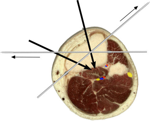
Within segment 2 and just distal to the tibial tuberosity, the safe corridor for half pins is either in a sagittal plane medial to the tibial crest or perpendicular to the anteromedial surface of the tibia (Fig. 5). Coronal plane pins can also be used should the surgeon wish to increase the angle between pins for a ‘delta’ fixator assembly [4].
Fig. 5.
Segment 2: just distal to the tibial tuberosity
The technique for inserting the medial face wire (from a posteromedial to anterolateral direction) should pay heed to stretching the gastrocsoleus muscle mass when pushing the wire down to bone. As for the coronal plane wire, the easiest method to locate its level is to palpate the anterior and posteromedial limits of the subcutaneous surface of the tibia and determine the midpoint—a transverse trajectory from this point in the coronal plane is the position for this wire. When passing the wire from the lateral aspect through the anterior compartment muscle mass, a reaction is occasionally elicited from the branch of the deep peroneal nerve to extensor hallucis longus; a repeat pass of the wire either 1–2 mm anteriorly or posteriorly will avoid this response.
The position for half pins and wires around the mid-shaft of the tibia is unchanged from the above (Fig. 6).
Fig. 6.
Segment 2: mid-shaft of the tibia
At the beginning of the metaphyseal flare (Fig. 7), the posterior tibial neurovascular bundle moves from a midline location to posteromedial. Care should be taken to move the medial face wire a little more anteriorly.
Fig. 7.
Segment 2: start of the distal metaphyseal flare
The anterior tibial vessels and deep peroneal nerve can be seen to migrate more anteriorly on the interosseous membrane. It is at this level that the deep peroneal nerve and anterior tibial vessels can be caught by a coronal plane wire—care needs to be taken by passing the wire down to bone and watching for reflexes from the toe extensors. In the event a reflex is elicited, either anterior or posterior repositioning of this wire can avoid injury to these structures.
Laterally, the superficial peroneal nerve lies in the peroneal compartment close to the intermuscular septum which divides anterior and lateral muscle groups. It pierces the fascia of the lateral compartment about a hand’s breadth above the ankle and travels to a position approximately in line with the 4th ray of the foot.
At this most distal portion of segment 2, the sagittal half pin should be inserted medial to the tendon of Tibialis anterior. Wires are inserted along the same corridors as the section above.
Segment 3
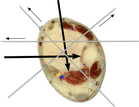
This spans across the widened metaphysis to the ankle joint (Fig. 8). The posterior tibial neurovascular bundle now lies posteromedially between flexor digitorum and flexor hallucis longus. The anterior tibial vessels are between extensor hallucis and extensor digitorum longus. Two additional wires are now possible:
The transfibular wire (not shown). It is important to dorsiflex the ankle fully before this wire is passed across the tibiofibular space (as is done with syndesmotic screws).
Another inserted behind the peroneal tendons but anterior to the lateral edge of the tendo Achilles. If this wire is pushed down to bone before the drill started, the sural nerve is unlikely to be picked up. This wire may transfix part of the distal belly of flexor hallucis longus—as such the great toe should be dorsiflexed when the wire is passed onto the posterior surface of the tibia. This wire also crosses the medial face wire at nearly 90°. Half pins are as the segment above, with care to insert the sagittal plane pin either medial to Tibialis anterior or between it and extensor hallucis longus.
Fig. 8.
Segment 3: proximal to the ankle joint
The hindfoot
Calcaneal wires and pins
The posterior tibial neurovascular bundle can usually be palpated. The medial wire is passed just posterior to it and driven across the calcaneum posterolaterally. The complementary wire is at 45–60°, passing from anterolateral (behind and a little distal to the peroneal tendons) to posteromedial (Fig. 9).
Fig. 9.
Segment 3: calcaneum and talus
Half pins are inserted from lateral to medial in two areas:
The posterior third of the body of the calcaneum (the pin can be inserted from posterior to anterior as an alternative direction)
The neck of the talus
Forefoot wires and pins
It is usually necessary to ‘capture’ the 1st and 5th metatarsals with crossed wires. The wires are passed obliquely and often pick up neighbouring metatarsals as well. The crossed arrangement helps keep the transverse arch of the foot, without forcibly flattening it as would be needed if only one wire is used between the metatarsals. If half pins are used, they need to be of smaller diameter than in the tibia and inserted into the 1st and 5th metatarsals as indicated.
Conclusion
This review uses surface and cross-sectional anatomy to present a method in remembering safe corridors for insertion of half pins and wires in the tibia and foot. It conveniently describes three segments in the tibia within which the safe corridors are consistent, thereby reducing the amount of information needed to be committed to memory.
References
- 1.ASAMI (1991) Operative principles of Ilizarov. Medi Surgical Video, Medicalplastic SRL, Milan, Italy
- 2.Catagni M (2002) Atlas for the insertion of transosseous wires and half pins. Medi Surgical Video, Department of Medicalplastic SRL, Milan, Italy
- 3.Faure C, Merloz P (1987) Atlas of transfixation. Springer Verlag
- 4.Giotakis N, Narayan B (2007) Stability with unilateral external fixation in the tibia. Strat Trauma Limb Recon 2(1):13–20 [DOI] [PMC free article] [PubMed]


