Abstract
[At very low Reynolds number, the regime in which fluid dynamics is governed by Stokes equations, a helix that translates along its axis under an external force but without an external torque will necessarily rotate. By the linearity of the Stokes equations, the same helix that is caused to rotate due to an external torque will necessarily translate. This is the physics that underlies the mechanism of flagellar propulsion employed by many microorganisms. Here, I examine the linear relationships between forces and torques and translational and angular velocities of helical objects to understand the nature of flagellar propulsion.]
Keywords: bacteria, motility, hydrodynamics, low Reynolds number
Much has been written about the fluid mechanics of the helical flagellum with which some microorganisms propel themselves [the earliest studies beginning with Ludwig (3)]. Recent theoretical studies include papers by Chwang and Wu (4), by Lighthill (5–7), by Garcia de la Torre and Bloomfield (8), and by Brennen and Winet (9). Like the classic paper by Taylor (10), these are aimed at deriving from first principles the flow around a moving helix, calculating the associated force and torque, and determining thereby the motion of the helix and a large attached body. The helical flagellum is supposed either to rotate as a whole, like a rigid corkscrew, or to deform continuously in a traveling helical wave, like a helical snake. The two motions are externally indistinguishable in the limit of vanishing thickness of the helical filament, but the latter case calls for some mechanism inside the flagellum to drive the wave. It has been shown that in the case of the bacterium Escherichia coli the flagellum simply rotates, driven by a rotary motor in or within the cell wall (11, 12). The flagellum is simply a rather gently curving helical filament of protein. Usually a cell has more than one flagellum. When the cell swims, its several flagella gather together into a helical bundle, the rotation of which generates a thrust that pushes the cell from the rear. Reversed rotation causes the bundle to come apart (13) and results, not in steady motion of the cell in the opposite direction, but in an erratic tumbling motion (14). In this note, only the steady forward propulsion of the cell driven by the rotating flagellar bundle will be considered.
Instead of calculating the hydrodynamic forces on a rotating flagellum of some particular shape, I want to develop some general relations by taking a different approach. Consider any propulsive device which consists of some rigid object rotating about a fixed axis. A corkscrew is only one example—the shape need not be that of a regular helix. Let us call the object, for short, a propeller. Indeed, an object shaped like a marine screw propeller could be an acceptable candidate. But whatever the shape, the rotation is to be so slow that its Reynolds number (ℜ) is very small. [The Reynolds number of an object of dimension a moving with velocity v through a fluid of density ρ and dynamic viscosity η is
 |
1 |
This is the ratio of the inertial forces to the viscous forces.] In bacterial propulsion ℜ is typically 10−4 or less. Inertial forces are utterly negligible. How a similar propeller would work at high Reynolds number is quite irrelevant. Imagine a ship in a sea of molasses with its propeller turning at one revolution per month (ℜ ≅ 10−3). I know of no theorem that would enable one to predict with certainty whether motion ahead or astern would result.
We consider only two degrees of freedom of the isolated propeller, rotation at angular speed ω around its axis and translation at velocity v along that axis, as shown in Fig. 1. These motions are caused by some external force F and some external torque N applied to the propeller by means not yet specified. At the same time, a force −F and a torque −N are exerted on the propeller by the surrounding fluid. In the low Reynolds number regime [Stokes equations govern the fluid dynamics:
 |
2 |
where p is the pressure and there are no derivatives of time. Therefore,] F and N must be linearly related to the v and ω:
 |
3a |
 |
3b |
We shall call the 2 × 2 matrix
 |
the propulsion matrix P of this propeller. [Hydrodynamicists call this object the resistance matrix (15).] The constants A, B, C, and D are proportional to the fluid viscosity η and depend otherwise only on the shape and size of the propeller. They scale with propeller size in this way: if every dimension of the propeller is increased by the factor k, the new propulsion matrix P′ has elements A′ = kA; B′ = k2B; C′ = k2C; and D′ = k3D.
Figure 1.
An isolated propeller, subjected to an external force F and an external torque N. It rotates at angular velocity ω and translates at velocity v.
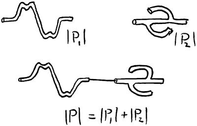
Of course, these constants will be somewhat modified by the ship or cell to which we shall eventually attach the propeller and which will be the actual source of external force and torque. But for the present we may think of the force and torque as applied by a thin, perfectly stiff, untwistable axial wire. Whether such “mathematical” wire can be found does not matter. Eventually, we shall be interested in the real flagellum’s stiffness. We may also use such a mathematical wire to connect two different propellers together to form a single propeller, as in Fig. 2. From our definition of the propulsion matrix, it follows that the propulsion matrix of the composite propeller is the sum of the individual matrices:
 |
4 |
This is true if the force of the fluid on the thin wire can be neglected, and if the two flows [elements of the propeller] are well separated. The off-diagonal elements of P are essential for propulsion; they couple rotation and translation. We shall now prove that B and C must be equal if Eq. 4 is true.
Figure 2.
Two propellers with propulsion matrices P1 and P2 (Upper) connected by a thin axial wire (Lower). The propulsion matrix of the composite propeller is P1 + P2.
We show first that B and C must have the same sign. Consider two cases: (i) Let the propeller be pushed by an external force F1 applied by an axial wire at speed v1. Constrain it from rotating by a torque N1 of precisely the strength required to make ω1 = 0. [By Eqs. 3a, the] force and torque are then given by:
 |
5a |
 |
5b |
In this case the external force F1 must do work because the torque does none. Hence, with signs defined as in Fig. 1, A must be positive. Similarly, if the propeller were rotated by an external torque N1 with v1 constrained to be zero, work would be done by N1, implying that D must be positive also. (ii) Now remove the torque N1 and apply a force F2 sufficient to cause the same linear speed v1 with the propeller free from external torque. [In this case, the propeller will rotate with some rotational speed ω2. By Eqs. 3a,
 |
6a |
 |
6b |
Therefore,]
 |
7 |
 |
8 |
But F2 cannot be greater than F1 because the change from case i to case ii amounted to the relaxation of a constraint—i.e., the removal of an external torque N1 that was doing no work. The argument can be made by invoking the minimum dissipation theorem for inertialess flows (16). If F2 were greater than F1, the rotationally unconstrained system of case ii could reduce its energy dissipation by reverting spontaneously to the kinematics of case i. We conclude that F2 ≤ F1. [In view of Eq. 8, BC/AD ≥ 0. Because A > 0 and D > 0, AD > 0; therefore,]
 |
9 |
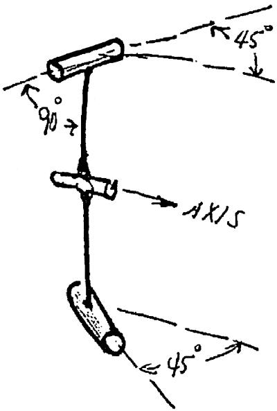
The next step in the proof is to exhibit [a special] propeller for which, manifestly, B = C. As shown in Fig. 3, it consists of two short rods mounted obliquely at the end of stiff radial wires of infinitesimal thickness [and of length a] attached to a stiff axial wire likewise of infinitesimal thickness, i.e., of negligible flow resistance. Let the rods be short compared with their distance from the axis and let the symmetry axis of each rod make an angle of 45° with the axial direction. It follows then from the symmetry of the rods with respect to the orthogonal directions, axial and circumferential, that the longitudinal force F associated with a circumferential speed aω will be the same as the circumferential force N/a associated with a longitudinal speed v. Consequently, the propulsion matrix Ps of this special propeller must have Bs = Cs. By scaling this propeller in size, we can make Bs have any desired magnitude, and by reversing the propeller’s handedness, we can make Bs have either sign.
Figure 3.
A special propeller with a symmetrical propulsion matrix (B = C). See the text.
Now suppose we have [a test] propeller for which Bt ≠ Ct. We could construct a special propeller with Bs = Cs = −(Bt + Ct)/2 and attach it in series with our [test] propeller by one of our thin, rigid axial wires. [The propulsion matrix of the composite propeller would be Pc = Ps + Pt] for which
 |
10 |
[But if Bt ≠ Ct, BcCc is negative,] in violation of Eq. 9. Hence, a propeller with Bt ≠ Ct cannot exist. Every propulsion matrix must be symmetrical. We have here a reciprocity theorem typical of a linear system. Note that it implies that a structure like our “special” propeller will have Bs = Cs even with the rods set at some other angle. It should perhaps be emphasized that the extremely idealized nature of our hypothetical special propeller and connecting hardware does not, in itself, compromise the rigor of the proof.
We turn now to the question of propulsion of the bacterial cell by a rigidly rotating flagellum or flagellar bundle, assured that the relevant properties of the propeller, at least in isolation, are completely specified by the three independent elements of its propulsion matrix, A, B, and D. The cell itself is characterized by the propulsion matrix P0, which is presumably diagonal, with its only nonzero elements A0 and D0. These are given exactly by the Stokes drag relations for translation and rotation as A0 = 6πηa and D0 = 8πηa3.
We now connect the propeller to the motor in the cell. We shall assume that the proximity of the cell does not seriously disturb the flow around the propeller. Our results would be strictly correct if we used a long thin wire as a propeller shaft. Because most of the flagellum is in fact relatively far from the cell, we may hope to achieve a reasonably good approximation.
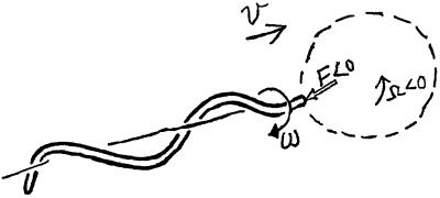
The cell, of course, must rotate continuously in a sense opposite to the propeller rotation, there being no external torques on the system. We denote by Ω the angular velocity of the cell. Both the flagellum and the cell must translate at the same speed v. The torque on the cell must be equal and opposite to the torque on the propeller; likewise, the force on the cell must be equal and opposite to the force on the propeller. Fig. 4 will help us to make a self-consistent assignment of signs. The propeller shown has been arbitrarily chosen to be a right-handed helix. The directions have been made consistent with the fact, not predicted by this general analysis, that a helical filament does tend to move like a corkscrew in a cork when it is rotated. With our sign convention, the off-diagonal elements of the propulsion matrix of a right-handed corkscrew will then be negative: B < 0. The motor will have to drive the propeller in the sense ω < 0 to propel the system to the right, that is with v > 0. The external force F acting on the propeller is negative, that is, directed toward the left. The counter rotation of the cell itself is negative: Ω < 0. With due regard to these signs, equality of action and reaction of both forces and torques at the propeller shaft requires
 |
11a |
 |
11b |
The rotation speed of the motor itself, that is, the speed of the “rotor” attached to the flagellum relative to the “stator” attached to the cell wall, is ω − Ω, which is greater in magnitude than ω. Let us call the motor speed Ωm and derive from Eqs. 11a the relation between v and Ωm:
 |
12 |
As expected, the swimming speed is proportional to Ωm. The torque N exerted by the motor on the propeller is
 |
13 |
Let us compare the power output of the motor, which is NΩm, with the least power that would be required to move the cell at speed v by any means of propulsion whatever, namely A0v2. The ratio of A0v2 to NΩm provides a definition of the propulsive efficiency ɛ. Using the relations above, we find
 |
14 |
It will be a good approximation to drop the B2 terms in the denominator, for it will turn out that B2 is considerably smaller than AD in practical cases. [For B2 ≪ AD, Eqs. 12 and 14 may be well approximated by
 |
15a |
and]
 |
15b |
To the same approximation, the factor D0/(D0 + D) is just the ratio ω/|Ωm|, which, to anticipate again, will be fairly close to unity in cases of interest. That is, the counter-rotation of the large cell is relatively slow compared with the rotational speed of the flagellum (17). [Therefore, Eqs. 15a can further be approximated by
 |
16a |
and]
 |
16b |
Consider now a flagellar propeller of some particular specified shape. Suppose we are free to scale it up or down in size by some factor k. The resulting propulsion matrix will have elements kAp, k2Bp, and k3Dp, where Ap, Bp, and Dp refer to some prototype of a particular size. Is there a size of propeller that maximizes ɛ for the propulsion of a cell of given A0? There is, as we find by substituting into Eq. 16ab:
 |
17 |
The maximum efficiency, ɛmax, is attained when k = A0/Ap and has the value
 |
18 |
ɛmax depends only on the shape of the propeller itself, a rather remarkable result. Given any propeller shape, Eq. 17 gives the greatest efficiency attainable in propelling anything with such a propeller, and the relation A = A0 tells us how to match the propeller to the object being propelled. Incidentally, A = A0 is just the condition under which the force required to drag the cell through the fluid at speed v is equal to the force required to drag the locked propeller through the fluid at the same speed. [Therefore, the swimming speed of a cell driven by a maximally efficient flagellum is
 |
19 |
The fractional error in these efficiency relations incurred by the approximations in Eqs. 15ab and 16ab is generally of the order of magnitude of ɛ itself, which, as we shall see, is not more than a few percent. There remains, of course, the unknown error arising from interference of the flow fields around cell and propeller. It seems unlikely that such an effect would increase the efficiency, so we are probably safe in regarding Eq. 18 as an upper bound on the propulsive efficiency attainable with a flagellum of a given shape. The efficiency of a flagellar bundle of the given shape will be lower still, owing to dissipation within the cross section of the bundle where the fluid between adjacent filaments is necessarily undergoing shear.
Figure 4.
A propeller in the shape of a right-handed helix connected to a spherical cell, both moving to the right at velocity v. The propeller and cell rotate in opposite directions, at angular velocities ω and Ω, respectively. The external force F acting on the propeller is directed to the left.
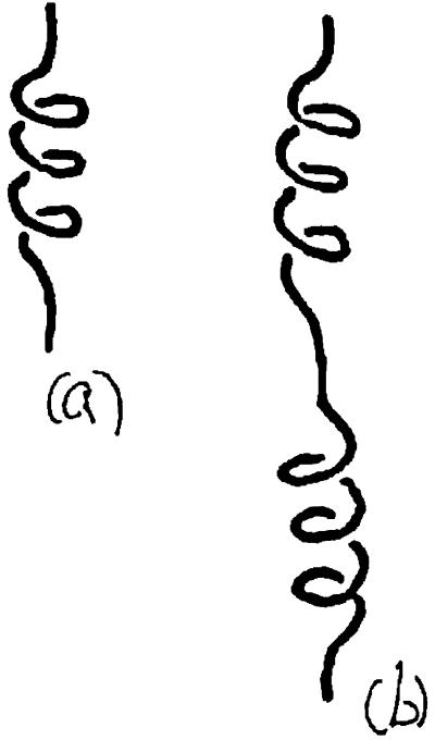
For any given shape of propeller, the elements of the propulsion matrix A, B, and D can be determined by very simple experiments with a model. Consider the propeller of Fig. 5a realized in the form of a steel wire. Let this object sink under its own weight, with its axis vertical, in a fluid of viscosity sufficient to ensure ℜ ≪ 1. Measure the sinking speed v1 and the speed of rotation Ω1:
 |
20a |
 |
20b |
(where W is the weight of the propeller in the fluid, of course). Now prepare a composite propeller consisting of the propeller of Fig. 5a joined rigidly to its mirror image. The propulsion matrix of this “racemic” composite (Fig. 5b) will be diagonal, with elements 2A and 2D. Measure the speed v2 with which this object sinks under its weight 2W in the same fluid,
 |
21 |
It should sink without rotating. The three measurements suffice to determine A, B, and D, through Eqs. 20a and 21. The maximal efficiency attainable with a propeller of the given shape, as expressed by the approximate Eq. 18, is determined by only two measurements, those of v1 and v2:
 |
22 |
The values of A, B, and D determined from Eqs. 20a and 21 contain the viscosity of the fluid. Dividing them by 6πη will normalize them so that the dimensions of A, B, and D are cm, cm2, and cm3, respectively, and the radius of the spherical cell to which the propeller would be matched for maximal efficiency is equal to A. In other words, the radius of spherical cell for which the model propeller is [most efficient] is that of a sphere that would sink at speed v2 if its weight in the fluid were W.
Figure 5.
Two propellers made of steel wire allowed to sink under their own weight, with axes vertical. b is a composite propeller consisting of propeller a joined rigidly to its mirror image.
A few propellers in the form of regular helices were tested by the method just described. The fluid used was Dow–Corning [silicon oil.] The results are given in Table 1.
Table 1.
[Elements of propulsion matrices and propulsion efficiencies for flagellar models dropped in silicon oil]
| L, cm | L/λ | Pitch angle, ° | A, cm | B, cm2 | D, cm3 | ɛmax, % | f, sec−1 |
|---|---|---|---|---|---|---|---|
| 5.2 | 5 | 55 | 0.67 | 0.032 | 0.076 | 0.48 | 89 |
| 7.8 | 5 | 39 | 0.71 | 0.038 | 0.06 | 0.78 | 85 |
| 9.4 | 5 | 20 | 0.74 | 0.018 | 0.031 | 0.34 | 188 |
| 3.1 | 3 | 55 | 0.48 | 0.023 | 0.053 | 0.46 | 62 |
| 7.5 | 7 | 56 | 0.91 | 0.053 | 0.13 | 0.54 | 100 |
[Test helices (Fig. 5) of length L, wavelength λ, and specified pitch angle were allowed to sink under their own weight in silicon oil (η ≈ 1,000 g⋅cm−1⋅sec−1). The sinking speeds and speeds of rotation were measured, and A, B, and D were determined through Eqs. 20a and 21; their values have been divided by 6πη, so that their dimensions are cm, cm2, and cm3, respectively. ɛmax is the maximal propulsion efficiency expected when the test helix is connected to a sphere of radius A (Eq. 22). f is the motor speed required to drive that sphere 20A⋅sec−1 (Eq. 19).]
Acknowledgments
We (A. D. T. Samuel, H. A. Stone, and H. C. Berg) thank Bob Macnab for his comments on the manuscript sent to E.M.P. May 12, 1978.
References
- 1.Purcell E M. Am J Phys. 1977;45:3–11. [Google Scholar]
- 2.Childress S. Mechanics of Swimming and Flying. New York: Cambridge Univ. Press; 1981. pp. 42–50. [Google Scholar]
- 3.Ludwig W. Z Vergl Physiol. 1930;13:397–504. [Google Scholar]
- 4.Chwang A T, Wu T Y. J Fluid Mech. 1976;75:677–689. [Google Scholar]
- 5.Lighthill M J. SIAM Rev. 1976;8:161–230. [Google Scholar]
- 6.Lighthill M J. J Eng Math. 1996;30:25–34. [Google Scholar]
- 7.Lighthill M J. J Eng Math. 1996;30:35–78. [Google Scholar]
- 8.Garcia de la Torre J, Bloomfield V A. Biophys J. 1977;20:49–68. doi: 10.1016/S0006-3495(77)85536-7. [DOI] [PMC free article] [PubMed] [Google Scholar]
- 9.Brennen C, Winet H. Annu Rev Fluid Mech. 1977;9:339–398. [Google Scholar]
- 10.Taylor G I. Proc R Soc London Ser A. 1952;209:447–461. [Google Scholar]
- 11.Berg H C, Anderson R A. Nature (London) 1973;245:380–382. doi: 10.1038/245380a0. [DOI] [PubMed] [Google Scholar]
- 12.Silverman M, Simon M. Nature (London) 1974;249:73–74. doi: 10.1038/249073a0. [DOI] [PubMed] [Google Scholar]
- 13.Macnab R M, Ornston M K. J Mol Biol. 1977;112:1–30. doi: 10.1016/s0022-2836(77)80153-8. [DOI] [PubMed] [Google Scholar]
- 14.Berg H C, Brown D A. Nature (London) 1972;239:500–504. doi: 10.1038/239500a0. [DOI] [PubMed] [Google Scholar]
- 15.Happel J, Brenner H. Low Reynolds Number Hydrodynamics. Englewood Cliffs, NJ: Prentice Hall; 1967. [Google Scholar]
- 16.Batchelor G K. An Introduction to Fluid Dynamics. New York: Cambridge Univ. Press; 1967. p. 228. [Google Scholar]
- 17.Lowe G, Meister M, Berg H C. Nature (London) 1987;325:637–640. [Google Scholar]


