Abstract
To improve the adhesive properties of artificial fibrillar contact structures, the attachment systems of beetles from the family Chrysomelidae were chosen to serve as a model. Biomimetic mushroom-shaped fibrillar adhesive microstructure inspired by these systems was characterized using a variety of measurement techniques and compared with a control flat surface made of the same material. Results revealed that pull-off force and peel strength of the structured specimens are more than twice those of the flat specimens. In contrast to the control system, the structured one is found to be very tolerant to contamination and able to recover its adhesive properties after being washed in a soap solution. Based on the combination of several geometrical principles found in biological attachment devices, the presented microstructure exhibits a considerable step towards the development of an industrial dry adhesive.
Keywords: biomimetics, microstructures, surface patterning, adhesion, attachment
1. Introduction
Fibrillar attachment systems have evolved several times independently in various animal groups (Gorb 2001; Gorb & Beutel 2001). Their geometrical features, such as contact splitting, high aspect ratio of single contact elements and their spatula-shaped heads, were found to be responsible for generating strong adhesion. The physical background of this phenomenon was intensively discussed in several recent publications (Arzt et al. 2003; Persson 2003; Persson & Gorb 2003; Chung & Chaudhury 2005; Gao et al. 2005). It was confirmed that adhesion-oriented geometry of biological fibrillar attachment systems may be employed to design artificial surfaces with enhanced adhesion.
There have been a few attempts to produce biomimetic fibrillar surfaces to amplify adhesion of a flat contact (Geim et al. 2003; Ghatak et al. 2004; Majidi et al. 2004; Peressadko & Gorb 2004; Northen & Turner 2005; Yurdumakan et al. 2005). However, the reported surfaces fabricated using various techniques ranging from laser technology to microlithography did not, in fact, mimic the natural adhesive structures, and they featured limited life cycle and overall gain in adhesion.
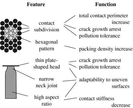
To improve the adhesive properties of artificial fibrillar contact structures, the attachment systems of beetles from the family Chrysomelidae were chosen to serve as a model. Based on the study of numerous species of these beetles, it has been previously shown that they are extremely specialized for adhering to smooth surfaces (Stork 1980, 1983; Pelletier & Smilowitz 1987; Gorb 2001). Analysis of the functional morphology of adhesive hairs on their tarsi (figure 1) allows fabrication of an advanced adhesive microstructure.
Figure 1.
Schematic of the functional morphology of biological model attachment system.
The purpose of the present work is to report on biomimetic mushroom-shaped fibrillar adhesive microstructure that is inspired by these natural attachment systems and represents a considerable step towards the development of an industrial dry adhesive.
2. Material and methods
2.1 Specimen preparation
Fibrillar specimens were produced by Gottlieb Binder GmbH (Holzgerlingen, Germany) at room temperature by pouring two-compound polymerizing polyvinylsiloxane (PVS; Coltène Whaledent AG, Altstätten, Switzerland) into the holed template lying on a smooth glass support. Prospective specimen height was defined by spacers between the support and a covering flat surface that was used to squeeze superfluous polymer out of the gap. After polymerization, the ready-to-use cast with Young's modulus of about 3 MPa (Peressadko & Gorb 2004) was removed from the template. The backside of the fibrillar casts was used for flat specimens.
2.2 Scanning electron microscopy
Two portions of a structured surface were used for scanning electron microscopy (SEM). The first part was employed to analyse the morphology of a fibrillar structure. To this end, the structure's backing was attached to a carbon double-sided tape fixed onto a specimen holder. The second part was used to study the contact formed between artificial fibrils and flat smooth surface. For this purpose, its structured side was adhered to a small cover glass attached to the same specimen holder. The specimens were sputter coated with about 6 nm of gold–palladium for electrical conductivity and imaged in a Hitachi-4800 high-resolution SEM at accelerating voltage of 3 kV.
2.3 Pull-off test
The adhesion generated by structured and flat PVS surfaces in contact with a smooth flat glass substrate was tested on a home-made microtribometer. It consisted of a motorized precise translation stage (Physik Instrumente GmbH, Karlsruhe, Germany) and a fixed flexible cantilever (Tetra GmbH, Ilmenau, Germany), whose deflection, used to determine the contact forces, was measured with fibre-optic sensors (MTI Instruments, Inc., Albany, New York). The forces detected were calibrated with known precise weights immediately prior to experiments. To guarantee full intimate contact during measurements in a flat-on-flat contact scheme, a passive self-aligning system of specimen holders was used (Varenberg et al. 2006b). PVS specimens were discs of 2.9 mm diameter and 1.5 mm height mounted on the cantilever, and a glass cover slide of 18×7×0.2 mm3 in size fixed on the translation stage was used as a substrate. The roughness average (Ra) of the glass and PVS surface was about 1 and 85 nm, respectively. Before the experiments, the specimens were washed with deionized water and liquid soap, and then dried in blowing nitrogen.
Each test started by preloading the specimens for 90 s. Under preloads between 50 and 130 mN, the real contact area was imaged with video zoom optics (Navitar Inc., Rochester, New York) to verify proper contact formation. Destructive interference of reflected white light in the glass–PVS interface resulted in a visualization of the real contact area as a much darker zone than the area that was out of contact. Subsequently, the pull-off force was measured while withdrawing the translation stage at a velocity of 700 μm s−1.
2.4 Peeling test
In these experiments, a PVS tape of 0.4 mm thickness and 25 mm width was adhered with its structured or flat side to a clean smooth glass substrate for a contact time of 30 s. Then, a constant load was applied to the tape at a variable angle from the substrate by fixing a dead weight to the tape edge and tilting the substrate. The angle between the tape and the substrate corresponding to a peeling crack speed of about 100 μm s−1 was determined, and the process was repeated for different loads varied in the range of 70–300 mN. Before the experiments, the specimens were washed with deionized water and liquid soap, and then dried in blowing nitrogen.
A peeling test was also used to estimate the effect of contamination on the proper function of both structured and flat surfaces. In these experiments, the peeling angle was kept equal to 12°, and the peeling load corresponding to a crack speed of about 900 μm s−1 was determined with clean and gradually contaminated specimens of both types. The degree of contamination was increased by placing the specimens on a dusty laboratory shelf between the evaluations of the peeling load. The shelf has not been touched over the last four years and dust particles ranging from a few micrometres to a few hundreds of micrometres in size have formed a uniform dust layer of a few hundreds of micrometres in height. Each time the specimens were placed on an untouched shelf surface, the increasing number of dust particles, which adhered to the specimens' surface in a naturally uncontrolled way, led to a subsequent decrease in their peeling strength. After finishing the contamination tests, the specimens were cleaned according to the above procedure and the peeling force was determined again to test their recovery ability. Portions of contaminated surfaces were also examined in SEM.
3. Results and discussion
3.1 Morphology
To reproduce the adhesive characteristics of the model biological system, its functional morphology was analysed and is represented in a simplified form in figure 1. Inspired by these design principles, a biomimetic mushroom-shaped fibrillar adhesive microstructure was fabricated. It is demonstrated in figure 2.
Figure 2.
Biomimetic mushroom-shaped fibrillar adhesive microstructure made of PVS. (a,c) View from above; (b,d) side view. LP, contact plate lip; NR, narrow neck; SH, pillar shaft.
While principles of contact subdivision (Autumn et al. 2000; Scherge & Gorb 2001; Arzt et al. 2003) and hexagonal patterning (Ball 2001; Gorb 2001) were sufficiently discussed as mechanisms of adhesion enhancement in biological hairy attachment devices, the form of natural terminal contact elements has not yet received proper attention. The thin plate at the biological adhesive hair tip (figure 1) is very different from the flat-punch geometry used in most previously reported artificial patterned adhesives (Geim et al. 2003; Glassmaker et al. 2004; Peressadko & Gorb 2004; Crosby et al. 2005). Since the most effective biological attachment systems use spatula- or mushroom-shaped rather than the flat-punch geometry, this feature, which seems to be very important from the viewpoint of stress concentration and crack arrest, was implemented in the presented artificial adhesive system.
Structured in a hexagonal order (figure 2a), this system consisted of mushroom-shaped pillars of about 100 μm in height, 60 μm in base diameter, 35 μm in middle diameter and 25 μm in diameter at the narrowed region just below the terminal contact plates. These plates were of about 40 μm in diameter and 2 μm in thickness at the lip edges (figure 2b,d). The area density of the terminal contact plates was about 40%.
3.2 Performance
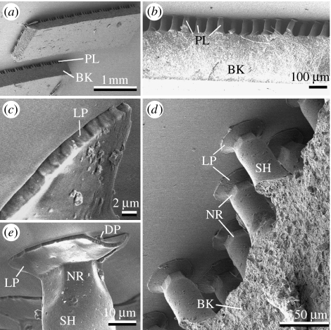
The contact formed by the studied PVS microstructure adhered to a smooth glass substrate is depicted in figure 3. It was found that the presence of terminal thin plates greatly improved the adaptability of the contact system. For instance, the terminal plates of the pillars, which were not ideally oriented perpendicular to the substrate, could still form a partial contact (figure 3b). These plates were even able to resist small surface unevenness or contaminations (figure 4d,e). Normally, only a part of the terminal plate was disabled in this case, while the rest of the plate remained in contact. This would be hardly possible having a flat-punch geometry.
Figure 3.
Structured PVS surface in contact with glass substrate. BK, backing; DP, dirt particle; LP, contact plate lip; NR, narrow neck; PL, pillar; SH, pillar shaft.
Figure 4.
Pull-off force measured between PVS and glass specimens as a function of preload. Inserts are binarized images of real contact area for flat and structured surfaces.
Figure 4 presents the pull-off force measured between the PVS specimens and the glass substrate. Results revealed that the structured specimens featured a pull-off force more than twice that of the flat specimens, while in both cases it was independent of the preload. Two typical binarized images of structured and flat real contact area are also shown. Image analysis demonstrated that the flat surface had formed a real contact area about twice that of the structured surface, thus confirming that adhesion does not depend on the contact area (Varenberg et al. 2006a).
A peeling strength analysis was performed according to the following expression:
| (3.1) |
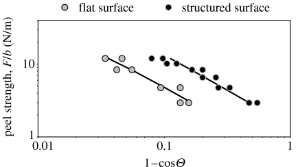
where F is the peeling force; d is the thickness of the adhesive tape; b is the width of the tape; E is the Young's modulus of the tape material; Θ is the peeling angle; and R is the energy required to fracture a unit area of interface (Kendall 1975). The fracture energy, R, of both structured and flat specimens was estimated using predefined values of peeling force and respective experimentally determined peeling angles. The mean fracture energy corresponding to a peeling crack speed of 100 μm s−1 was found to be 1.38 and 0.51 J m−2 for structured and flat tape, respectively. These values demonstrate again that the structured specimens featured adhesion more than twice that of the flat specimens. These results are also represented in figure 5, where the experimental data are plotted along with the theoretical predictions calculated from expression (3.1) using the mean values of the fracture energy.
Figure 5.
Dependence of peel strength on peel angle for a constant crack speed of 100 μm s−1 obtained for flat and structured PVS surfaces. Markers correspond to experimental data and solid lines to theoretical predictions.
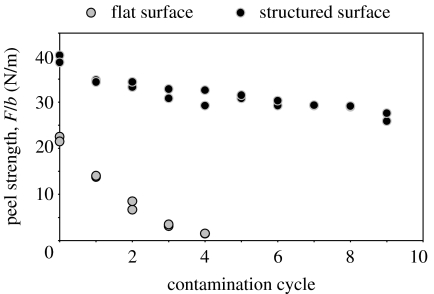
Figure 6 demonstrates the effect of contamination on the peel strength of both flat and structured specimens. It is clearly seen that while the flat specimens experience dramatic decrease in peel strength and almost completely loose their ability to adhere during the very first contamination cycles, the structured specimens are much more tolerant to the degree of contamination and continue functioning steadily. Washed surfaces of both types were able to recover in full their peel strength, thus demonstrating that the observed adhesion reduction has resulted solely from contamination.
Figure 6.
Effect of contamination on the peel strength of flat and structured PVS surfaces.
3.3 Analysis
The most recent empirical explanation of adhesion enhancement with contact subdivision is that adhesion is proportional to a total contact perimeter (Varenberg et al. 2006a). This results in a scaling effect with finer structures exhibiting stronger adhesion. However, attachment properties of any surface are defined not only by its ability to adhere, but also by the forces resisting contact deformation required to maximize contact zone and generate adhesion. Adhesion and the forces resisting contact deformation act in the opposite directions and the resulting pull-off force, or the external load needed to detach one surface from another, is the difference between the two. Thus, an ultimate requirement for an effective attachment system is to generate maximal adhesion with minimal elastic strain energy. For instance, the structured contact composed of pillars having a uniform height will perform a better pull-off force than the same structure having a stochastic distribution of pillar heights. This despite both contacts will presumably generate approximately the same adhesion in a loaded compressed state.
Low contact stiffness of a fibre array results in minimizing contact forces and providing a high adaptability of a structured surface to a substrate. The presence of structural hierarchical levels, which are widely spread in biological systems, is one of the features used to achieve this purpose. For instance, insects use two levels of outgrowths in their attachment organs, spiders evolved three levels (Gorb 2001) and geckos employ four levels of hierarchy (Hiller 1968; Autumn et al. 2000; Huber et al. 2005; Rizzo et al. 2006). In contrast to most previously reported artificial patterned adhesives (Geim et al. 2003; Glassmaker et al. 2004; Peressadko & Gorb 2004; Crosby et al. 2005), which have only one hierarchy level of structuring, the presented mushroom-shaped fibrillar adhesive involves two levels. This presumably makes the system more tolerant to uneven real surfaces. The first hierarchic level is represented by pillars, which provide some general adaptability, and the second level is represented by the flat terminal plates, which can adapt to local surface irregularities owing to their thin lips and narrowed flexible joints with pillars. These two hierarchical levels resemble, in a way, a recently reported sandwich-shaped structured adhesive, where pillars were enclosed between their backing and an upper covering thin film (Glassmaker et al. 2006). Another advantage of this second hierarchic level is that thin lips at terminal plates are more effective in arresting crack growth, which is a very important result of contact subdivision (Chung & Chaudhury 2005).
One more remarkable feature of contact splitting is related to its pollution resistance. Experimental evidence for the reduction of contamination in a gecko hairy adhesive system has been recently reported for the first time (Hansen & Autumn 2005). Self-cleaning in gecko setae was explained by an energetic disequilibrium between the adhesive forces attracting a dirt particle to the substrate and those attracting the same particle to one or more spatulae. SEM observations of contaminated artificial surfaces studied in the present work show that the advantage of the structured systems can be explained by several additional effects: (i) the thin contact plate terminating each pillar is flexible enough to form a reliable contact even in the presence of small dirt particles (figure 3e); (ii) large particles can slip into the space between pillars (figure 7) and be accommodated there with a negligible effect on contact features; and (iii) disabled pillars do not alter the performance of their neighbours.
Figure 7.
Contaminated structured PVS surface. Arrows point to dirt particles sunk into the space between the pillars. SP, small dirt particles adhered to flat contact plate.
4. Conclusion
Adhesive properties of a biomimetic mushroom-shaped fibrillar adhesive microstructure and a control flat surface made of the same material were characterized using a variety of measurement techniques. Despite rather coarse patterning, adhesive features of the structured surface were more than twice as effective as of the flat one. The higher tolerance of the patterned surface to contamination as well as its ability to recover by washing in a liquid soap solution were experimentally verified.
Based on the combination of several principles found in biological attachment devices, the presented microstructure exhibits a considerable step towards the development of an industrial dry adhesive. It can be currently produced in any size up to an A4 format and is suitable for use in a protective tape for sensitive glass surfaces or in reusable pads for the attachment of small objects to smooth surfaces. In fact, it was successfully used in the attachment feet of a 120 g wall-walking robot (Daltorio et al. 2005).
Acknowledgments
This work was supported by the Federal Ministry of Education, Science and Technology, Germany to S.G. (project BioFuture 0311851).
References
- Arzt E, Gorb S, Spolenak R. From micro to nano contacts in biological attachment devices. Proc. Natl Acad. Sci. USA. 2003;100:10 603–10 606. doi: 10.1073/pnas.1534701100. [DOI] [PMC free article] [PubMed] [Google Scholar]
- Autumn K, Liang Y.A, Hsieh S.T, Zesch W, Chan W.P, Kenny T.W, Fearing R, Full R.J. Adhesive force of a single gecko foot-hair. Nature. 2000;405:681–685. doi: 10.1038/35015073. [DOI] [PubMed] [Google Scholar]
- Ball P. Oxford University Press; Oxford, UK: 2001. The self made tapestry: pattern formation in nature. [Google Scholar]
- Chung J.Y, Chaudhury M.K. Roles of discontinuities in bio-inspired adhesive pads. J. R. Soc. Interface. 2005;2:55–61. doi: 10.1098/rsif.2004.0020. [DOI] [PMC free article] [PubMed] [Google Scholar]
- Crosby A.J, Hageman M, Duncan A. Controlling polymer adhesion with “pancakes”. Langmuir. 2005;21:11 738–11 743. doi: 10.1021/la051721k. [DOI] [PubMed] [Google Scholar]
- Daltorio, K. A., Gorb, S., Peressadko, A., Horchler, A. D., Ritzmann, R. E. & Quinn, R. D 2005 A robot that climbs walls using micro-structured polymer feet. In Proc. Int. Conf. Climbing and Walking Robots, London, UK, pp. 131–138.
- Gao H.J, Wang X, Yao H.M, Gorb S, Arzt E. Mechanics of hierarchical adhesion structures of geckos. Mech. Mater. 2005;37:275–285. doi: 10.1016/j.mechmat.2004.03.008. [DOI] [Google Scholar]
- Geim A.K, Dubonos S.V, Grigorieva I.V, Novoselov K.S, Zhukov A.A. Microfabricated adhesive mimicking gecko foot-hair. Nat. Mater. 2003;2:461–463. doi: 10.1038/nmat917. [DOI] [PubMed] [Google Scholar]
- Ghatak A, Mahadevan L, Chung J.Y, Chaudhury M.K, Shenoy V. Peeling from a biomimetically patterned elastic film. Proc. R. Soc. A. 2004;460:2725–2735. doi: 10.1098/rspa.2004.1313. [DOI] [Google Scholar]
- Glassmaker N.J, Jagota A, Hui C.-Y, Kim J. Design of biomimetic fibrillar interfaces: 1. Making contact. J. R. Soc. Interface. 2004;1:23–33. doi: 10.1098/rsif.2004.0004. [DOI] [PMC free article] [PubMed] [Google Scholar]
- Glassmaker, N. J., Jagota, A., Chaudhury, M. K. & Hui, C.-Y. 2006 Contact and adhesion mechanics of biomimetic fibrillar interfaces. In Proc. Adhes. Soc. 93–95.
- Gorb S.N. Springer; New York, NY: 2001. Attachment devices of insect cuticle. [Google Scholar]
- Gorb S.N, Beutel R.G. Evolution of locomotory attachment pads of hexapods. Naturwissenschaften. 2001;88:530–534. doi: 10.1007/s00114-001-0274-y. [DOI] [PubMed] [Google Scholar]
- Hansen W.R, Autumn K. Evidence for self-cleaning in gecko setae. Proc. Natl Acad. Sci. USA. 2005;102:385–389. doi: 10.1073/pnas.0408304102. [DOI] [PMC free article] [PubMed] [Google Scholar]
- Hiller U. Untersuchungen zum Feinbau und zur Funktion der Haftborsten von Reptilien. Z. Morphol. Tiere. 1968;62:307–362. doi: 10.1007/BF00401561. [DOI] [Google Scholar]
- Huber G, Gorb S.N, Spolenak R, Arzt E. Resolving the nanoscale adhesion of individual gecko spatulae by atomic force microscopy. Biol. Lett. 2005;1:2–4. doi: 10.1098/rsbl.2004.0254. [DOI] [PMC free article] [PubMed] [Google Scholar]
- Kendall K. Thin-film peeling—the elastic term. J. Phys. D: Appl. Phys. 1975;8:1449–1452. doi: 10.1088/0022-3727/8/13/005. [DOI] [Google Scholar]
- Majidi, C., Groff, R. & Fearing, R. 2004 Clumping and packing of hair arrays manufactured by nanocasting. In Proc. ASME IMECE, 62142.
- Northen M.T, Turner K.L. A batch fabricated biomimetic dry adhesive. Nanotechnology. 2005;16:1159–1166. doi: 10.1088/0957-4484/16/8/030. [DOI] [Google Scholar]
- Pelletier Y, Smilowitz Z. Specialized tarsal hairs on adult male Colorado potato beetles, Leptinotarsa decemlineata (Say), hamper its locomotion on smooth surfaces. Can. Entomol. 1987;119:1139–1142. [Google Scholar]
- Peressadko A, Gorb S.N. When less is more: experimental evidence for tenacity enhancement by division of contact area. J. Adhes. 2004;80:1–15. doi: 10.1080/00218460490430199. [DOI] [Google Scholar]
- Persson B.N.J. On the mechanism of adhesion in biological systems. J. Chem. Phys. 2003;118:7614–7621. doi: 10.1063/1.1562192. [DOI] [Google Scholar]
- Persson B.N.J, Gorb S. The effect of surface roughness on the adhesion of elastic plates with application to biological systems. J. Chem. Phys. 2003;119:11 437–11 444. doi: 10.1063/1.1621854. [DOI] [Google Scholar]
- Rizzo N.W, Gardner K.H, Walls D.J, Keiper-Hrynko N.M, Ganzke T.S, Hallahan D.L. Characterization of the structure and composition of gecko adhesive setae. J. R. Soc. Interface. 2006;3:441–451. doi: 10.1098/rsif.2005.0097. [DOI] [PMC free article] [PubMed] [Google Scholar]
- Scherge M, Gorb S.N. Springer; Berlin, Germany: 2001. Biological micro- and nanotribology: nature's solutions. [Google Scholar]
- Stork N.E. Experimental analysis of adhesion of Chrysolina polita (Chrysomelidae, Coleoptera) on a variety of surfaces. J. Exp. Biol. 1980;88:91–107. [Google Scholar]
- Stork N.E. The adherence of beetle tarsal setae to glass. J. Nat. Hist. 1983;17:583–597. [Google Scholar]
- Varenberg M, Peressadko A, Gorb S, Arzt E. Effect of real contact geometry on adhesion. Appl. Phys. Lett. 2006a;89:121 905. doi: 10.1063/1.2356099. [DOI] [Google Scholar]
- Varenberg M, Peressadko A, Gorb S, Arzt E, Mrotzek S. Advanced testing of adhesion and friction with a microtribometer. Rev. Sci. Instrum. 2006b;77:066105. doi: 10.1063/1.2214692. [DOI] [Google Scholar]
- Yurdumakan B, Raravikar N.R, Ajayan P.M, Dhinojwala A. Synthetic gecko foot-hairs from multiwalled carbon nanotubes. Chem. Commun. 2005;30:3799–3801. doi: 10.1039/b506047h. [DOI] [PubMed] [Google Scholar]


