Abstract
Self-healing is receiving an increasing amount of worldwide interest as a method to autonomously address damage in materials. The incorporation of a self-healing capability within fibre-reinforced polymers has been investigated by a number of workers previously. The use of functional repair components stored inside hollow glass fibres (HGF) is one such bioinspired approach being considered. This paper considers the placement of self-healing HGF plies within both glass fibre/epoxy and carbon fibre/epoxy laminates to mitigate damage occurrence and restore mechanical strength. The study investigates the effect of embedded HGF on the host laminates mechanical properties and also the healing efficiency of the laminates after they were subjected to quasi-static impact damage. The results of flexural testing have shown that a significant fraction of flexural strength can be restored by the self-repairing effect of a healing resin stored within hollow fibres.
Keywords: self-repair, biomimetic, mechanical properties, fractography
1. Introduction
Advances in materials technologies have largely been responsible for major performance improvements in many engineering structures and continue to be the key in determining the reliability, performance and cost effectiveness of such systems. Lightweight, high strength and high stiffness fibre-reinforced polymer (FRP) composite materials are leading contenders to improve the efficiency and sustainability of many forms of transport. In addition, they offer immense scope for incorporating multifunctionality due to their hierarchical internal architecture. One limiting factor in their wider exploitation is relatively a poor performance under impact loading, a crucial aspect of any safety critical design, leading to a significant reduction in strength, stiffness and stability.
For example, carbon fibre-reinforced plastic (CFRP) used in aerospace applications is typically assigned an allowable strain level of less than 0.4% (Richardson & Wisheart 1996; Zhou 1998) whereas commercially available carbon fibres typically have a strain to failure of approximately 1.5%. This results in conservative design and higher weight structures. The inability to plastically deform results in energy absorption via the creation of matrix cracks and delaminations, which can be difficult to detect visually. Self-healing has the potential to mitigate the damage resulting from an impact event, thereby providing an opportunity to improve the design allowables for FRPs or offer other benefits such as reduced maintenance and inspection schedules.
Conceptual inspiration from nature is not new, and many engineering approaches can be considered to have been inspired by observing natural systems. The healing potential and repair strategies of living organisms is increasingly of interest to designers seeking lower mass structures with increased service life who wish to progress from a conventional damage tolerance philosophy. Naturally occurring ‘materials’ have evolved into highly sophisticated, integrated, hierarchical structures that commonly exhibit multifunctional behaviour (Curtis 1996). Inspiration and mimicry of these microstructures and micromechanisms offer considerable potential in the design and improvement of material performance (Kassner 2005), but many of the biological processes involved are extremely complex. Bioinspired self-healing using hollow fibres embedded within a structure has been investigated at different length-scales in several materials by various authors, e.g. bulk concrete (Li et al. 1989; Dry 1994; Dry & McMillan 1996), bulk polymers (Chen et al. 2002; Kassner 2005) and polymer composites (Dry 1996; Motoku et al. 1999; Zako & Takano 1999; Bleay et al. 2001). The latter has seen exciting developments in recent years, e.g. (Kessler & White 2001; White et al. 2001; Kessler et al. 2003; Brown et al. 2004, 2005a,b; Pang & Bond 2005a,b; Trask & Bond 2006), using the inspiration of biological self-healing applied with broadly traditional engineering approaches.
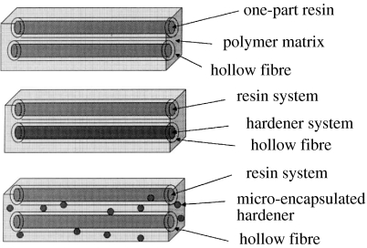
Hollow glass fibres (HGFs; Hucker et al. 1999, 2002) are used in preference to embedded microcapsules (Brown et al. 2003; Rule et al. 2005) because they offer the advantage of being able to store functional agents for self-repair as well as integrating easily with and acting as a reinforcement. A typical hollow fibre self-healing approach used within composite laminates could take the form of fibres containing a one-part resin system, a two-part resin and hardener system, or a resin system with a catalyst or hardener contained within the matrix material (Bleay et al. 2001). A schematic of these approaches is shown in figure 1.
Figure 1.
Schematic of different hollow fibre self-healing approaches (Bleay et al. 2001).
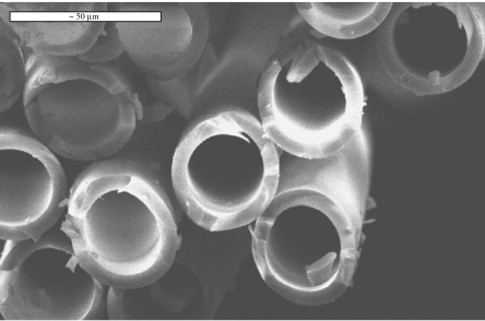
A bespoke HGF making facility (Hucker et al. 1999, 2002) has been used to produce HGF between 30 and 100 μm diameter with a hollowness of approximately 50%, figure 2. These are then embedded within either glass fibre-reinforced plastic (GFRP) or CFRP and infused with uncured resin to impart a self-healing functionality to the laminate. During a damage event, some of these hollow fibres will fracture, thus initiating the recovery of properties by ‘healing’ whereby a repair agent passes from within any broken hollow fibres to infiltrate the damage zone, and acts to ameliorate the critical effects of matrix cracking and delamination between plies and, most importantly, prevent further damage propagation. This release of repair agent mimics the bleeding mechanism in biological organisms (e.g. human thrombosis).
Figure 2.
Typical hollow glass fibre (35 μm external diameter with 55% hollowness fraction).
The exact nature of the self-healing method will depend upon (i) the nature and location of the damage, (ii) the choice of repair resin, and (iii) the influence of the operational environment. The self-healing fibres can be introduced within a laminate as additional plies at each interface, at damage critical interfaces or as individual filaments spaced at predetermined distances within each ply. In order to more fully understand and optimize the healing process, two parallel studies were undertaken in glass- and carbon-reinforced epoxy systems, respectively. A translucent glass/epoxy laminate provides good visualization of damage occurrence and the healing process when viewed with transmission microscopy, however, a carbon/epoxy laminate is opaque and therefore, to enhance visualization, a UV fluorescent dye (Ardrox 985) was added to the healing resin in both studies.
2. Specimen manufacture
2.1 Self-healing GFRP
The HGF chosen for this study had an external diameter of 60±3 μm and an internal diameter of approximately 40 μm yielding a hollowness fraction (ratio of internal to external area) of approximately 55%. This larger fibre diameter (compared to figure 2) gives a greater volume for healing agent storage. Once manufactured, the individual fibres were consolidated within a 913 epoxy resin film (42 gsm) which was selected to match the baseline laminate material. The healing resin can then be infused into the individual filaments using a vacuum-assisted capillary action. Once the ends have been sealed (Bostik BondFlex 100HMA high modulus silicone sealant), the infused hollow fibre layers (which can now be considered as standard ‘pre-preg’ plies) are incorporated into a laminate stacking sequence as required, and processed according to the resin film manufacturer's guidelines.
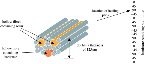
A 16-ply composite laminate with a [0°/+45°/90°/−45°]2s stacking sequence manufactured from pre-impregnated E-glass/913 epoxy resin (Hexcel composites) was selected for the first evaluation of the HGF self-healing approach. The self-healing filaments were introduced at four 0°/45° damage critical ply interfaces that were identified and reported previously (Trask & Bond 2006), as shown in figure 3. An epoxy resin system (CYTEC Cycom 823) was selected as the healing resin owing to the need to match the chemistry of the host laminate, its availability as a two-part system permitting inclusion in separate storage filaments, low-viscosity profile and time to gelation 30 min after mixing. Furthermore, it was observed experimentally that the individual components of the two-part Cycom 823 were sufficiently robust to survive the host laminate curing process (120°C for 1 h) after infiltration into the hollow filaments within the laminate stack.
Figure 3.
Location of resin and hardener self-healing filaments intermingled within an E-glass ply in the 16-ply stacking sequence of the composite laminate.
Panels of 200×200×2.5 mm were prepared according to the pre-preg manufacturer's instructions. Each panel was then sectioned into coupons 20×50 mm for testing. After cutting, the edges of the samples are sealed with a two-part rapid curing epoxy system (Araldite Rapid) to prevent any healing resin loss through the exposed ends of the hollow fibres.
2.2 Self-healing CFRP
It is imperative that any embedded HGF does not detrimentally affect the innate mechanical performance of a FRP, but provides a sufficient volume of healing resin to address any damage. Thus, the incorporation of HGF as discrete plies was deemed unsuitable for CFRP laminates as it would effectively produce a hybrid glass–carbon laminate and result in a significant reduction to their outstanding mechanical properties. A less intrusive approach was devised whereby a small number of individual HGF's were distributed within individual CFRP plies to act as dispersed storage vessels for the healing agent. Therefore, the distribution of HGF within a CFRP laminate poses a problem of balancing disruption of the host laminate architecture against delivery of adequate healing resin.
Pre-impregnated T300 carbon fibre/914 epoxy resin (Hexcel Composites) was selected as the host material as it is widely used in aerospace applications. A quasi-isotropic stacking sequence of 16 plies was prepared as a 230×160×2.5 mm plate. Two different HGF distributions (fibre spacing of 70 and 200 μm, respectively) were wound directly onto uncured CFRP plies prior to lamination to investigate the effect of HGF on the host laminate properties and the healing efficacy of different healing agent volumes. HGF was located at two 0°/−45° interfaces within the lay-up as follows:
The inclusion of HGF within the CFRP stack was such that short lengths (10–20 mm) of exposed HGF protruded from the panel edges. This facilitated the vacuum-assisted infiltration of the HGF after cure of the laminate with a two-part epoxy resin healing agent (Cytec Cycom 823) immediately prior to testing.
3. Mechanical testing
3.1 Self-healing GFRP
Four-point bend flexural strength testing according to ASTM D6272-02 was selected to characterize the strength of standard GFRP and self-healing specimens. This configuration ensures a region of uniform bending stress in the area of damage between the loading noses. A support span to depth ratio of 32 : 1 and a support span to load span ratio of 3 : 1 were selected. Six repeated tests were conducted using a loading rate of 5 mm min−1 on a Roell Amsler hydraulic test frame fitted with a 25 kN load cell. A linear potentiometric displacement transducer was used to record mid-span deflection, which was logged through a PC running Instron data acquisition software.
In the case of damaged specimens, a three-point bend indentation test using a hardened steel hemisphere of 4.63 mm diameter with the specimen back face supported by a steel ring (OD=34 mm, ID=19 mm) was used to create repeatable damage. A peak load of 2500 N was used to initiate matrix shear cracks and delamination within the laminate. In the case of the laminate containing the self-healing specimens, this was permitted to heal by heating to 100°C (from ambient) in an air circulation oven and held at this temperature for 2 h. This heating was acceptable as it allowed some degree of control during the study and matched the environment of the intended aerospace application.
The results in table 1 indicate that the inclusion of HGF imparts an initial strength reduction of 16%. The control laminate and self-healing laminate with no healing had comparable damage tolerance both in terms of the damage size and the residual failure strength (typically 72–74%). After healing, it was found that a laminate had a residual strength of 87% compared with the undamaged control and 100% compared with an undamaged self-healing laminate albeit with greater standard deviation.
Table 1.
Summary of flexural strength and healing efficacy for GFRP.
| specimen description | flexural strength (MPa) | percent retained strength |
|---|---|---|
| control laminate—no damage | 668±13 | 100 |
| self-healing laminate—no damage | 559±12 | 84 |
| control laminate—damaged (2500 N peak load) | 479±32 | 72 |
| self-healing laminate—damaged, no repair | 494±7 | 74 |
| self-healing laminate—damaged +2 h at 100°C | 578±28 | 87 |
3.2 Self-healing CFRP
As described above, the configuration and manufacture of self-healing CFRP was somewhat different to the GFRP. Ten specimens (100×20×2.5 mm) were cut from a plate with the use of a water-cooled diamond grit saw. The sample edges were polished with SiC paper (P2500) to avoid any unwanted edge effects. Samples were then dried, sealed in sample bags and stored in a temperature- and humidity-controlled environment prior to testing. Immediately prior to commencing any mechanical testing, the HGF within each specimen were infiltrated, using a vacuum-assisted technique, with pre-mixed, two-part epoxy healing resin (Cytec Cycom 823).
Quasi-static impact damage was imparted to each specimen using a hardened steel of 5 mm spherical indenter supported by a steel ring of 27 mm outer diameter and 14 mm inner diameter mounted on a Hounsfield H20K-W electromechanical test machine. Different load levels were used to introduce an indentation representative of barely visible impact damage (BVID) into the composite laminate. The indentations were stopped at a peak load of either 1700 or 2000 N. Up to this point, the damage is contained within the laminate and can be likened to BVID, as the impact surface suffers a minor indent and the back face experiences minimal distortion due to back face delamination.
After indentation, the specimens were subjected to 70°C for 45 min to reduce healing resin viscosity (25 cps) and facilitate infiltration into damage sites, followed by cure at 125°C for 75 min. While this process diverges from the original aim of achieving autonomic healing, the use of a pre-mixed resin and elevated temperature is an attempt to mitigate some of the shortcomings of the Cycom 823 and demonstrate the greatest healing efficiency possible with this system. No resin system exhibiting all desirable attributes (i.e. low viscosity, insensitivity to mix ratio, rapid cure under ambient conditions and unlimited shelf life) is currently available. However, from a practical perspective, temperature activation provides excellent control of cure initiation, eliminating time constraints on the testing/manufacturing process.
Four-point bend flexural testing (ASTM-D6272-02) was again used to assess the self-healing efficiency of the resulting CFRP. A support span to depth ratio of 32 : 1 and a support span to load span ratio of 3 : 1 were selected. Results were obtained from 10 undamaged, 5 damaged and 5 healed specimens. An Instron 8800 controller/data logger was used to control the test machine and record data. Specimens were monitored to ensure a consistent failure mode and optical microscopy used to record detailed observations.
The results of the four-point bend flexural testing are shown in table 2. This compares the performance of undamaged, damaged and healed specimens for the two HGF pitch spacings alongside a control CFRP laminate with no HGF.
Table 2.
Summary of flexural strength and healing efficacy for CFRP.
| specimen type | undamaged (s.d.) | damaged (s.d.) | healed (s.d.) | |||
|---|---|---|---|---|---|---|
| @1700 N | @2000 N | @1700 N | @2000 N | |||
| control CFRP | strength (MPa) | 583.3 (13.4) | 538.6 (55.5) | 405.0 (65.5) | — | — |
| percent of baseline undamaged | 100% | 92% | 69% | — | — | |
| HGF spaced @70 μm | strength (MPa) | 534.9 (12.6) | 527.3 (8.0) | 443.7 (47.4) | 529.0 (16.7) | 519.6 (28.8) |
| percentage of baseline undamaged | 92% | 90% | 76% | 91% | 89% | |
| HGF spaced @200 μm | strength (MPa) | 568.8 (18.6) | 490.1 (31.9) | 401.0 (52.9) | 523.4 (19.1) | 466.6 (21.8) |
| percentage of baseline undamaged | 98% | 84% | 69% | 90% | 80% | |
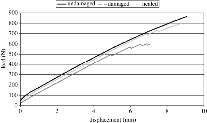
Figure 4 shows typical load–displacement curves from the flexural testing. The relative placement of the undamaged, damaged and healed traces for 70 μm HGF spacing gives a clear representation of the effects of damage and healing events on the flexural performance for CFRP with embedded HGF.
Figure 4.
Comparative load–displacement curves under four-point bend for undamaged, damaged and healed for 70 μm spaced HGF.
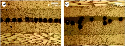
Analysis of table 2 shows that the 70 μm fibre spacing resulted in the largest reduction in undamaged strength (8%). This can be attributed to a significant disruption in fibre architecture (figure 7). However, after a quasi-static impact at 2000 N peak load, this configuration exhibited a significant amount of damage tolerance compared with the 200 μm fibre spacing and control laminates. The large volume fraction of HGF also provides a considerable reservoir of healing agent as shown by a 97% recovery of undamaged strength (equivalent to 89% of the undamaged strength of the control laminate).
Figure 7.
HGF spaced at 70 μm showing (a) good embedment and (b) fibre clumping within host laminate.
Figure 4 shows that a damaged specimen containing HGF under load experiences a number of intermittent decreases in load as failure is approached. This is probably attributable to the propagation of matrix cracks and delaminations up to a critical level at which they affect the load-bearing performance of the laminate. Conversely, the healed specimen appears to suppress these damage sites, inhibiting crack propagation and thereby delaying the failure of the laminate to higher load levels. Figure 4 also highlights the effectiveness of self-healing as the load–displacement curve for the healed laminate lies close to the undamaged curve.
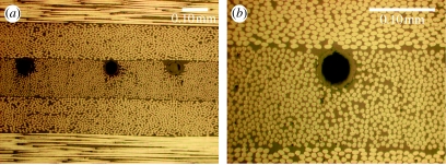
The 200 μm HGF spacing specimens exhibit little reduction in undamaged strength (2%) attributable to the reduced disruption to the host laminate (figure 8). These specimens behaved similarly to the control laminate when damaged, presumably due to the limited amount of HGF available for crushing. However, healed samples achieved 82% of their undamaged strength (equivalent to 80% of the undamaged strength of the control laminate), despite the significantly lower volume of available healing resin.
Figure 8.
HGF spaced at 200 μm showing (a) consistent spacing and (b) excellent embedment within host laminate.
Both HGF spacings investigated (70 and 200 μm) show similar trends, experiencing an initial reduction in flexural strength in the undamaged state compared with an unmodified control. This can be attributed to three effects:
Distortion of the reinforcing fibre architecture.
Generation of resin-rich regions (crack nucleation/propagation sites).
Displacement of reinforcing fibres with non-structural HGF (reduction in carbon fibre volume fraction).
4. Laminate microstructure and damage analysis
Specimens from different test panels were sectioned and polished for microstructural examination. This provided a visual assessment of the disruption caused by the different HGF configurations on the host GFRP and CFRP laminates and identified any inconsistencies present. Furthermore, it provided images to accurately determine the mode of damage propagation through the material.
4.1 Self-healing GFRP
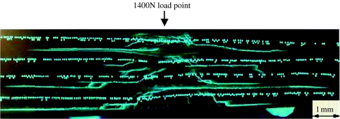
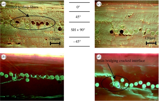
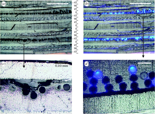
A damaged and healed GFRP specimen was examined to determine whether healing resin had infiltrated the damage zone. A cross-section of the healed damage illuminated under UV light is shown in figure 5, which clearly illustrates the extent of the infiltration by the healing resin into the damage zone when viewed along the 0° fibre direction. This result suggests that the four self-healing layer locations were ideally placed within the complex damage network to fully infuse the damage site. To understand the mechanism involved in the self-healing of the damage zone, further microscopic examinations were undertaken. This examination indicated the occurrence of crushed hollow fibres under the impact zone (figure 6a,b) and healing resin bridging fracture surfaces (figure 6c,d).
Figure 5.
Impact damaged cross-section of [0°/+45°/90°/−45°]2s GFRP laminate containing healing filaments at the +45°/90° and −45°/90° interfaces.
Figure 6.
Crushed-healing fibres located under the impact site viewed under (a) normal and (b) UV illumination. Healing resin bridging cracked interface viewed under (c) normal and (d) UV illumination.
4.2 Self-healing CFRP
A fibre spacing of 70 μm (figure 7) highlighted several issues about the resulting quality of embedding HGF within a laminate. This small pitch spacing was selected to ensure that the HGF were in close proximity and thereby facilitate a high degree of healing efficiency. However, during preparation, HGF could be mislocated resulting in disruption to the host ply (figure 7b). This was attributed to fluctuations in the fibre pitch control at low HGF spacing combined with poor tackiness of the 914 epoxy resin at ambient temperature. This was seen to result in lengths of HGF detaching from and reattaching to the surface producing fibre clumping and resin-rich regions post-cure.
A fibre spacing of 200 μm resulted in a much higher integrity laminate (figure 8). The resin-rich regions surrounding the HGF are minimized and there was no evidence of fibre clumping. The large spacing between fibres allowed the low tackiness of the 914 resin system to hold them in place, any that did detach were able to reattach without interfering with neighbouring fibres. The large spacing between the HGF permitted excellent consolidation during cure, further improving overall HGF embedment and reducing disruption to the laminate.
Microscopic analysis of samples after quasi-static indentation highlighted the mode of damage development and the interaction with the HGF. The cross-sectional damage distribution was typical of an impact damage event. A localized ‘crushing’ zone was evident on the upper surface followed by shear cracks and delaminations of increasing length through the thickness of the laminate culminating in the largest delamination at the back face between the final two plies of the stack.
The process of self-healing is reliant upon the occurrence of two phenomena:
HGF fibre fracture initiated by a damage event and
connectivity between HGF and damage network within material.
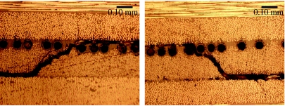
The region of HGF immediately under the impactor was subject to ‘crushing’ forces, the consequences of which were difficult to discern clearly using optical microscopy. However, the majority of HGF fracture within the laminate is evident from figure 9a where shear cracks and delaminations are seen to intercept regions of HGF. Furthermore, figure 9b shows similar damage infiltrated with healing resin mixed with fluorescent dye. It can be seen from this image that the larger delaminations (greater than 30 μm) contain little or no healing resin. This could be due to the inability of capillary action alone to draw significant volumes of resin into the relatively wide cracks, combined with the limited lengths of HGF available for delivery of resin (test specimen width provided approx. 40 mm HGF length adjacent to damage site).
Figure 9.
(a) Damage distribution within laminate, (b) damage infiltration with healing resin and fluorescent dye, (c) delaminations deviating from interface and (d) propagating along interface causing HGF fracture.
As expected, delaminations were observed to propagate along interfaces between plies of dissimilar fibre direction. It can be seen that this initiates HGF fracture via two mechanisms. In figure 9c, clusters of HGF cause deviation of a delamination, presumably due to a fibre cluster and the resulting resin-rich region causing a weakness in the laminate. However, the propagating crack passes directly through HGF causing fibre rupture and release of healing resin. In figure 9d, HGF are ruptured as the delamination propagates along a ply interface. This suggests their fracture toughness is similar to the surrounding epoxy matrix—a desirable situation for encouraging HGF fracture.
The presence of intra-ply shear cracks linking delaminations provide connectivity between different damage sites in the laminate and facilitate healing at multiple interfaces. Shear cracks can be seen to initiate HGF fracture by similar mechanisms to delaminations (figure 10). However, the width of shear cracks is generally smaller than delaminations (approx. 10 μm compared with approx. 30 μm) and so encourage a stronger capillary action to transport healing resin.
Figure 10.
Intra-ply shear cracks intercepting HGF within a self-healing CFRP laminate.
The number of fractured HGF depends very much on the severity of the impact and their location within the laminate stack. This provides an ability to tailor for a specific impact energy threshold. In the example shown, approximately 40% of the overall HGF were damaged but with a very uneven distribution throughout the laminate thickness. With regard to the proportion of healing resin which emerges from individual HGF upon fracture, initial studies have shown a range from entire evacuation at gross delamination sites to localized evacuation after matrix cracking. The rate at which a healing agent fills a damage site is a function of the viscosity and the capillary driving force. Once the release and mixture of the two components from adjacent HGF is initiated, the flow into damage sites is offset by an increasing viscosity as the system begins to polymerize. Thus, the infiltration period is limited by the time to gelation, which is approximately 30 min. Post-evacuation, the HGF are still capable of sustaining some load and there is no evidence that empty HGF act to initiate new damage.
5. Conclusions
This work has shown that a hollow-fibre self-healing approach can be used for the repair of advanced composite structures. Hollow glass fibres containing a two-part epoxy healing resin can be manufactured and incorporated within a conventional autoclave processing, indicating that this healing approach can be readily applied to the existing composites manufacturing techniques. The specific placement of self-healing plies or individual fibres to match a critical damage threat has been shown to repair internal matrix cracking and delaminations throughout the thickness of a laminate. Such a system offers significant potential in restoring structural integrity to a composite component during service and prolonging residual life after a damage event.
A series of mechanical tests were undertaken to evaluate the influence on the flexural strength of incorporating HGF plies into a GFRP laminate. The results indicate that the inclusion of hollow fibres gives an initial strength reduction, albeit with an increase in damage tolerance. However, after self-healing of an impact damaged laminate, it was found that residual strengths of 87% compared with an undamaged baseline non-healing laminate and 100% compared with an undamaged self-healing laminate were achieved.
The incorporation of individual HGF within a CFRP laminate (at fibre spacings of 70 and 200 μm, respectively) has also been shown to produce minimal degradation in flexural strength and disruption to fibre architecture. At fibre spacings of over three fibre diameters (200 μm), very good embedment of the HGF can be achieved, even on the most demanding 0°/45° interface. The presence of uniformly distributed HGF at a ply interface does not appear to cause obvious crack path deviation, suggesting that they do not create sites of weakness. However, small clusters of HGF combined with resin-rich regions can cause significant disruption resulting in crack path deviation. Intra-ply shear cracks and delaminations during an impact event do result in HGF fracture and the release of healing resin into the interconnected damage sites. However, there is evidence to suggest that if crack faces separate by more than 30 μm, capillary forces may be insufficient, or there may be inadequate resin volume released to fully infiltrate the damage. This inevitably leads towards a system which can provide bleeding under positive pressure to ensure complete infiltration. In general, these results suggest that bioinspired self-healing is now possible for advanced composite structures.
Further work is currently ongoing to create more realistic damage conditions within the laminates and apply compression after impact testing in order to achieve a more rigorous assessment of the effects of HGF on the host laminate and the subsequent healing performance. However, it is noted that in these studies, the healing process is based on a far from optimized healing resin system. Much works remains to be done in developing a healing agent suited to this application, providing controllable initiation on demand, robustness in stoichiometry and longevity in the uncured state. In addition, studies are underway with regard to a second generation of self-healing capability in a composite whereby a continuous healing capability is conferred via a vascular network of resin supply.
Acknowledgments
The authors wish to acknowledge the financial support of the European Space Agency and the UK Engineering and Physical Sciences Research Council for funding various aspects of this research under ESTEC Contract No.: 18131/04/NL/PA and grant nos. GR/TO3390 and GR/T17984, respectively.
Footnotes
One contribution of 9 to a themed supplement ‘Self-healing polymers and composites’.
References
- Bleay S.M, Loader C.B, Hawyes V.J, Humberstone L, Curtis P.T. A smart repair system for polymer matrix composites. Composites A. 2001;32:1767–1776. doi: 10.1016/S1359-835X(01)00020-3. [DOI] [Google Scholar]
- Brown E.N, Kessler M.R, Sottos N.R, White S.R. In situ poly(urea-formaldehyde) microencapsulation of dicyclopentadiene. J. Microencapsulation. 2003;20:719–730. doi: 10.1080/0265204031000154160. [DOI] [PubMed] [Google Scholar]
- Brown E.N, White S.R, Sottos N.R. Microcapsule induced toughening in a self-healing polymer composite. J. Mater. Sci. 2004;39:1703–1710. doi: 10.1023/B:JMSC.0000016173.73733.dc. [DOI] [Google Scholar]
- Brown E.N, White S.R, Sottos N.R. Retardation and repair of fatigue cracks in a microcapsule toughened epoxy composite—part I: manual infiltration. Compos. Sci. Technol. 2005a;65:2466–2473. doi: 10.1016/j.compscitech.2005.04.020. [DOI] [Google Scholar]
- Brown E.N, White S.R, Sottos N.R. Retardation and repair of fatigue cracks in a microcapsule toughened epoxy composite—part 2: in situ self-healing. Compos. Sci. Technol. 2005b;65:2474–2480. doi: 10.1016/j.compscitech.2005.04.053. [DOI] [Google Scholar]
- Chen X, Dam M.A, Ono K, Mal A.K, Shen H, Nutt S.R, Sheran K, Wudl F. A thermally re-mendable cross-linked polymeric material. Science. 2002;295:1698–1702. doi: 10.1126/science.1065879. [DOI] [PubMed] [Google Scholar]
- Curtis P.T. Multifunctional polymer composites. Adv. Perform. Mater. 1996;3:279–293. doi: 10.1007/BF00136792. [DOI] [Google Scholar]
- Dry C. Matrix cracking repair and filling using active and passive modes for smart timed release of chemicals from fibres into cement matrices. Smart Mater. Struct. 1994;3:118–123. doi: 10.1088/0964-1726/3/2/006. [DOI] [Google Scholar]
- Dry C. Procedures developed for self-repair of polymer matrix composites. Compos. Struct. 1996;35:263–269. doi: 10.1016/0263-8223(96)00033-5. [DOI] [Google Scholar]
- Dry C, McMillan W. Three-part methylmethacrylate adhesive system as an internal delivery system for smart responsive concrete. Smart Mater. Struct. 1996;5:297–300. doi: 10.1088/0964-1726/5/3/007. [DOI] [Google Scholar]
- Hucker M, Bond I.P, Foreman A, Hudd J. Optimisation of hollow glass fibres and their composites. Adv. Compos. Lett. 1999;8:181–189. [Google Scholar]
- Hucker M.J, Bond I.P, Haq S, Bleay S, Foreman A. Influence of manufacturing parameters on the tensile strengths of hollow and solid glass fibres. J. Mater. Sci. 2002;37:309–315. doi: 10.1023/A:1013648211761. [DOI] [Google Scholar]
- Kassner M.E, et al. New directions in mechanics. Mech. Mater. 2005;37:231–259. doi: 10.1016/j.mechmat.2004.04.009. [DOI] [Google Scholar]
- Kessler M.R, White S.R. Self-activated healing of delamination damage in woven composites. Composites A. 2001;32:683–699. doi: 10.1016/S1359-835X(00)00149-4. [DOI] [Google Scholar]
- Kessler M.R, White S.R, Sottos N.R. Self-healing structural composite materials. Composites A. 2003;34:743–753. doi: 10.1016/S1359-835X(03)00138-6. [DOI] [Google Scholar]
- Li V.C, Lim Y.M, Chan Y.W. Feasibility of a passive smart self-healing cementitious composite. Composites B. 1989;29B:819–827. [Google Scholar]
- Motoku M, Vaidya U.K, Janowski G.M. Parametric studies on self-repairing approaches for resin infused composites subjected to low velocity impact. Smart Mater. Struct. 1999;8:623–638. doi: 10.1088/0964-1726/8/5/313. [DOI] [Google Scholar]
- Pang J.W.C, Bond I.P. Bleeding composites—damage detection and self-repair using a biomimetic approach. Composites A. 2005a;36:183–188. doi: 10.1016/j.compositesa.2004.06.016. [DOI] [Google Scholar]
- Pang J.W.C, Bond I.P. A hollow fibre reinforced polymer composite encompassing self-healing and enhanced damage visibility. Compos. Sci. Technol. 2005b;65:1791–1799. doi: 10.1016/j.compscitech.2005.03.008. [DOI] [Google Scholar]
- Richardson M.O.W, Wisheart M.J. Review of low-velocity impact properties. Composites A. 1996;27:1123–1131. doi: 10.1016/1359-835X(96)00074-7. [DOI] [Google Scholar]
- Rule J.D, Brown E.N, Sottos N.R, White S.R, Moore J.S. Wax-protected catalyst microspheres for efficient self-healing materials. Adv. Mater. 2005;17:205–208. doi: 10.1002/adma.200400607. [DOI] [Google Scholar]
- Trask R.S, Bond I.P. Biomimetic self-healing of advanced composite structures using hollow glass fibres. Smart Mater. Struct. 2006;15:704–710. doi: 10.1088/0964-1726/15/3/005. [DOI] [Google Scholar]
- White S.R, Sottos N.R, Moore J, Geubelle P, Kessler M, Brown E, Suresh S, Viswanathan S. Autonomic healing of polymer composites. Nature. 2001;409:794–797. doi: 10.1038/35057232. [DOI] [PubMed] [Google Scholar]
- Zako M, Takano N. Intelligent materials systems using epoxy particles to repair microcracks and delamination in GFRP. J. Intell. Mater. Syst. Struct. 1999;10:836–841. doi: 10.1106/YE1H-QUDH-FC7W-4QFM. [DOI] [Google Scholar]
- Zhou G. The use of experimentally-determined impact force as a damage measure in impact damage resistance and tolerance of composite structures. Compos. Struct. 1998;42:375–382. doi: 10.1016/S0263-8223(98)00089-0. [DOI] [Google Scholar]


