

Abstract
Many neural disorders are associated with aberrant activity in specific cell types or neural projection pathways embedded within the densely-wired, heterogeneous matter of the brain. An ideal therapy would permit correction of activity just in specific target neurons, while leaving other neurons unaltered. Recently our lab revealed that the naturally-occurring light-activated proteins channelrhodopsin-2 (ChR2) and halorhodopsin (Halo/NpHR) can, when genetically expressed in neurons, enable them to be safely, precisely, and reversibly activated and silenced by pulses of blue and yellow light, respectively. We here describe the ability to make specific neurons in the brain light-sensitive, using a viral approach. We also reveal the design and construction of a scalable, fully-implantable optical prosthetic capable of delivering light of appropriate intensity and wavelength to targeted neurons at arbitrary 3-D locations within the brain, enabling activation and silencing of specific neuron types at multiple locations. Finally, we demonstrate control of neural activity in the cortex of the non-human primate, a key step in the translation of such technology for human clinical use. Systems for optical targeting of specific neural circuit elements may enable a new generation of high-precision therapies for brain disorders.
Keywords: neurons, brain, neurology, psychiatry, control, channelrhodopsin-2, halorhodopsin, viruses, cell types
1. INTRODUCTION
Many diseases of the human brain and nervous system are related to dysfunction of specific neuron types, which undergo pathological changes in number, excitability, anatomy, or synaptic connectivity. These changes lead, via altered neural circuit activity, to the perceptual, cognitive, emotional, and motor deficits associated with various neurological and psychiatric illnesses. For example, temporal lobe epilepsy is associated with increased excitability and connectivity of specific excitatory neurons1 and the loss of specific kinds of inhibitory interneurons2 in the hippocampus, whereas schizophrenia is associated with atrophy of a specific kind of inhibitory neuron in the prefrontal cortex3. One tantalizing possibility is that these cell classes, or other cell types within the affected neural circuits, may serve as novel and powerful clinical targets. By activating and silencing specific cell classes, perhaps in an adaptive way that depends upon the state of the neural circuit, we may be able to devise efficacious, side effect-free treatments for a multitude of neurological and psychiatric diseases. As an example, a disease in which a specific kind of neuron has become pathologically overexcitable (as in the case of epilepsy) may be treatable via cell-specific neural silencing, whereas a disease in which a specific neuron has become underactive (as in the case of schizophrenia) may be treatable via cell-specific neural activation. However, until recently, tools precise enough to perform this kind of neural-circuit level activity sculpting have not existed. Neurologists and psychiatrists have altered neural activity in the brain via the use of non cell-type specific electromagnetic methods (e.g., deep brain stimulation (DBS) and transcranial magnetic stimulation (TMS)), showing that stimulating a single bulk chunk of neural tissue within the brain can reliably (but often only partially) alleviate symptoms of disorders as diverse as depression4, epilepsy5, chronic pain6, Parkinson's disease7, and cluster headache8. These stimulation technologies overcome some of the issues associated with other methods, such as the irreversibility of surgical ablation of brain tissue9, and the widespread side effects associated with many drugs10. However, systematic principles of how to control aberrant activity in neural circuits have not been described, in part because of the nonspecific nature of electrical and magnetic stimulation: these fields cannot be focused at a distance due to their fundamental physical properties, and these fields cannot be targeted to specific cell types within a volume of tissue, due to the relative nonselectivity of the action of such fields upon neurons.
Over the last few years, we have developed a set of tools that permit specific genetically-defined excitable cells, such as neurons of different classes, to be activated and silenced with different colors of light11,12. These tools center around a set of naturally-occurring membrane proteins that, when exposed to light of the appropriate wavelength, move ions from one side of the plasma membrane to the other. The light-activated cation channel channelrhodopsin-2 (abbreviated ChR2, from the green algae C. reinhardtii), when expressed in neurons, makes them optically activatable by millisecond-timescale pulses of blue light (Fig. 1Ai, 1B). The light-activated chloride pump halorhodopsin (abbreviated Halo or NpHR, from the archaebacterium N. pharaonis) similarly makes neurons electrically silenceable by pulses of yellow light (Fig. 1Aii, 1C). Together, these molecular tools, when expressed in an appropriate ratio, can enable bi-directional control of neural activity by pulses of blue and yellow light (Fig. 1Aiii, D), enabling spike-level neural activity control. These molecules can be targeted to neurons by any of the means available to modern biotechnology, including the use of viruses or transgenic methods.
Fig. 1.
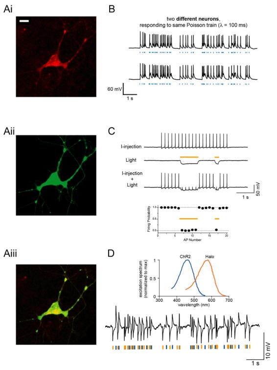
A, Neuron expressing channelrhodopsin-2 fused to mCherry (Ai; bar, 20 [μm) and halorhodopsin fused to GFP (Aii); overlay shown in Aiii. B, Poisson trains of spikes elicited by pulses of blue light (blue dashes), in two different neurons. C, Light-driven spike blockade, demonstrated (Top) for a representative hippocampal neuron, and (Bottom) for a population of neurons (n = 7). I-injection, neuronal firing induced by pulsed somatic current injection (300 pA, 4 ms). Light, hyperpolarization induced by periods of yellow light (yellow dashes). I-injection + Light, yellow light drives Halo to block neuron spiking, leaving spikes elicited during periods of darkness intact. D, Top, action spectrum for ChR2 overlaid with absorption spectrum for N. pharaonis halorhodopsin. Bottom, Hyperpolarization and depolarization events induced in a representative neuron by a Poisson train of alternating pulses (10 ms) of yellow and blue light. Adapted from11 and 12.
Ideally we would be able to discover, for each disease, which neural cell targets offer the greatest therapeutic potential, and, as importantly, what patterns of activity must be imposed in order to optimally correct the pathological state. In this way, we will reveal principles of neural control, which inform as to how to optimally resculpt the aberrant activity in the brain that contributes to illness. If proven safe and efficacious, we may also be able to use our optical neural control technologies directly as a therapy, sensitizing specific targets in the human brain to light, and then activating, silencing, or reshaping their activities at will. In this report, we describe a pipeline of technologies which we hope will in the short term help us investigate the principles of controlling neural circuits, and soon lead to optical prosthetics that can be used to directly remedy aberrant activity in corrupted human brain circuits. We here describe the ability to specifically target neurons in the mouse brain, using a viral approach. We also present a scalable, fully-implantable optical prosthetic capable of delivering light of appropriate intensity and wavelength to targeted neurons at arbitrary 3-D locations within the brain, enabling activation and silencing of specific neuron types at multiple locations. This device can be implanted in the brains of animals in order to reveal principles of neural control, and also serves as a prototype of optical prosthetics that may be practical for human use. In order to demonstrate the translational potential of this technology in humans, we close this paper with a demonstration of light-evoked neural activity in a non-human primate.
2. METHODOLOGY
2.1 Virus making
Replication incompetent lentiviruses were produced via triple transfection of plasmids containing the promoter and gene of interest (e.g., F(CK)-Halo-GFP or F(CK)-ChR2-GFP), the viral helper plasmid (pΔ8.91), and the pseudotyping plasmid (pMD2.G, encoding the coat protein VSV-G). Briefly, HEK293FT cells (Invitrogen) were plated onto four T175 flasks in D10 medium (comprising DMEM + 10% FBS + 1% pen-strep, 1% sodium pyruvate, and 1% sodium bicarbonate). At 100% confluence, cells were transfected with DNA using Fugene: we mixed 22 micrograms of plasmids containing the promoter and gene of interest, 15 micrograms of pΔ8.91, and 5 micrograms of pMD2.G, with 132 microliters of Fugene 6 and 4.5 mL of MEM, prepared according to the instructions of the manufacturers of Fugene. 24 hours later, the cells were washed with D10 and then given 30 mL of virus production media (comprising Opti-MEM w/ GlutaMAX-I + 1% pen-strep, 1% sodium pyruvate, and 1% sodium bicarbonate). 48 hours later, we harvested the supernatant, filtered it through a 0.45 micron filter flask (pre-wetted with D10), and then ultracentrifuged the filtrate over a 20% sucrose cushion at 22000 rpm in a SW-28 rotor for 2 hours at 4°C. We then resuspended the pellet in 30 microliters of PBS over a period of several hours, and aliquotted the virus for storage at −80°C.
2.2 Mouse virus injection
Viruses were tested for efficacy in sensitizing specific neuron types to being activated/silenced by light by being injected into the cerebral cortex of mice. We anesthetized mice with 1.25-2% isoflurane and placed them into a custom stereotax, and used a dental drill to make a small craniotomy, through which we then injected 1-2 microliters of virus into the cerebral cortex of the mouse brain. The virus was injected through a pulled borosilicate glass pipette (tip ∼5 microns wide; shank ∼4 mm long), pulled with a Sutter P-97 puller. This glass pipette was connected to a Hamilton syringe (placed in a syringe pump, from Harvard Apparatus) via a thin plastic tube filled with silicone oil. Virus infusion was carried out by actuating the Harvard Apparatus pump to inject slowly (e.g., 0.1 microliters per minute) over a period of 20 minutes. After the viral payload was delivered, we waited 10-20 minutes for the virus to diffuse away from the site of injection before withdrawing the pipette at a slow rate (e.g., 2 mm/min). The scalp of the mouse was then sealed with Vetbond, and the animal administered buprenorphine and returned to its home cage.
2.3 Slice visualization
One to four weeks after virus injection, we cut acute slices of brain tissue in order to assess the targeted cells for strength and specificity of gene expression, as described in 13. Briefly, mice were anesthetized with isoflurane and decapitated, and the brains were removed to ice cold cutting solution (87 mM NaCl, 25 mM NaHCO3, 25 mM glucose, 75 mM sucrose, 2.5 mM KCl, 1.25 mM NaH2PO4, 0.5 mM CaCl2 and 7 mM MgCl2, bubbled with 95% O2/5% CO2). Time between death and completion of brain removal was less than 1 minute. Brains were then blocked and glued to a dish for cutting with a vibrating tissue slicer (Leica VT1000S) into sections 240 microns thick. Slices were incubated at 35°C for 30 minutes, then stored at room temperature. Slices were acutely examined in physiological saline (125 mM NaCl, 25 mM NaHCO3, 25 mM glucose, 2.5 mM KCl, 1.25 mM NaH2PO4, 2 mM CaCl2, and 1 mM MgCl2). At this time, cells were examined electrophysiologically through whole-cell patch clamp (access resistance, 4-8 megaohms), conducted with a Molecular Devices Multiclamp 700B setup.
2.4 Optical modeling
Optical modeling and data analysis were done on a PC using MATLAB, and plotted in MATLAB or Excel.
2.5 Primate physiology
Basic methods were as described in 14. Briefly, a craniotomy and plastic chamber implantation was performed over the frontal eye field (FEF) region of the cortex of a rhesus macaque which had been prepared with a headpost, and trained to fixate upon a point. Recordings were made with tungsten microelectrodes (1-2 megaohm impedance) which were slowly advanced through cortical tissue until single units were isolated, acquiring data via a Multichannel Acquisition Processor from Plexon, Inc. Spike recordings were filtered, and spikes isolated using an interactively-set threshold. To facilitate precise and repeatable optical stimulation and recording, we designed and fabricated a recording chamber insert with a grid of evenly-spaced holes, for optimal placement of electrodes and optical fibers.
3. RESULTS
3.1 Intact tissue expression in mouse
We have developed mammalian codon-optimized forms of channelrhodopsn-2 and halorhodopsin, which we abbreviate as hChR2 and Halo12. We have inserted these genes into a lentiviral vector which allows us to clone in different promoters, or DNA regulatory elements, upstream of the gene of interest. For example, the CaMKII promoter targets predominantly excitatory neurons (Fig. 2). We have developed a pipeline for obtaining promoters by cloning them out of bacterial artificial chromosomes (BACs) and then inserting them into lentiviral plasmids upstream of hChR2 or Halo. We then create small virus test batches, and subsequently rapidly screen promoter strength and selectivity in the mouse brain. By screening promoters in a wholesale fashion, we hope to identify and validate new candidate promoters for targeting specific cell types.
Fig. 2.
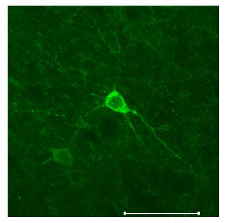
Neurons in the mouse brain expressing Halo-GFP under the CaMKII promoter, which preferentially labels excitatory neurons15. Scalebar, 50 μm.
3.2 Laser/fiber stimulation
To activate channelrhodopsin-2 and halorhodopsin molecules in mammalian neurons requires light of the appropriate color at a radiant flux of 10 mW/mm2 or greater, for maximal activation11,12,16. A radiant flux of 1 mW/mm2 will activate approximately 50% of the molecules, and a radiant flux of 0.1 mW/mm2 will activate very few of the molecules11,12,16. Since light is absorbed and scattered as it passes through tissue, this means that relatively bright light sources are needed to activate neurons embedded in tissue; furthermore, it implies that for any given light source, there will be heterogeneity in the power that reaches neurons at various distances from the light source. In order to develop a reliable testbed for activation and silencing of genetically-sensitized neurons with blue and yellow light, we constructed a system capable of coupling two strong lasers into a single optical fiber. We used two diode-pumped solid state (DPSS) lasers, a yellow (593 nm) 30 mW laser and a blue (473 nm) 200 mW laser (Aixiz Int'l.). These lasers can be activated for milliseconds at a time when triggered by TTL pulses. Two mirrors on adjustable gimbals (Fig. 3) steered the beams from these lasers into a fiber collimator (Thorlabs F810SMA), with the assistance of a dichroic element (Chroma) that reflects blue light and passes yellow light, thus bringing the two laser beams into collinearity. Into the collimator was inserted an SMA-terminated multimode fiber, 200 microns in diameter, capable of passing light throughout the visible range. The free end of the fiber, highly polished, could then be inserted into the brain of an experimental animal (see Section 3.6 for data). The power coming out of the fiber approached 800 mW/mm2 in the blue, sufficient to stimulate ChR2, and 110 mW/mm2 in the yellow, sufficient to stimulate Halo. In a mouse, a thin polyimide tube trimmed to the correct length, and inserted into the brain to stereotactically target the brain region of interest, serves easily as a guide cannula for inserting the fiber; gluing a thin washer onto the fiber helps prevent insertion of the fiber into the brain beyond the desired point.
Fig. 3.
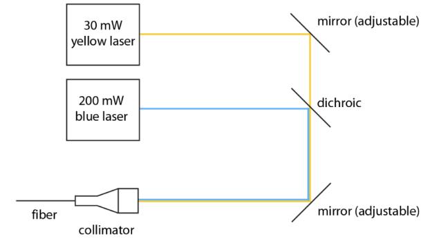
Schematic of a setup that allows blue and yellow light to be focused down a fiber to be implanted inside the head, for bi-directional control of a single kind of neuron at a single site within the brain, or for activation and silencing of two different kinds of neuron at a single site within the brain.
3.3 3-D LED arrays: the concept
While simple and flexible, the laser setup described above is expensive, bulky, and consumes a lot of power. Furthermore, since it requires optical fibers to be inserted into the brain that are simultaneously connected to a heavy, fixed laser, use of such a system constrains the movement of animals and increases the risk of tangling or breakage of optical fibers. These problems worsen if insertion of multiple fibers is desired. In addition, optical fibers emit light only at their end, meaning that an optical fiber damages a significant volume of brain tissue, compared to the amount of brain tissue that is illuminated.
A 3-D array of LEDs capable of targeting arbitrary brain structures would enable us to activate, silence, and resculpt activity throughout multiple brain regions. Unlike an optical fiber, which can only deliver light to a single point in the brain per penetrating device, a linear array of LEDs inserted into the brain could deliver light to points in the brain up and down the probe. Such a device must meet several criteria: it must be compact (human DBS electrodes are <1.5 mm wide), it must be capable of delivering bright light into deep brain structures, and it must not heat the brain beyond an acceptable limit (typically 1°C). Clearly it would be optimal to devise a probe that is inexpensive, compact, power-efficient, self-contained, and capable of exerting optical control over a large region of brain tissue while causing a minimum of brain damage. In order to meet these design goals, we have chosen to design 3-D arrays of compact, inexpensive, long-lasting, and bright light-emitting diodes (LEDs), capable of targeting arbitrary brain regions for activation or silencing. One way to make a 3-D array of LEDs, as schematized in Fig. 4, is to create a 2-D array of 1-D probes. Each 1-D probe projects vertically down into the brain, and supports a set of alternating blue and yellow LEDs. The 1-D probe is encased inside a glass capillary that electrically and thermally isolates the LEDs from the brain; the heat is wicked up the 1-D probe to cool the LEDs. The 2-D array is assembled by placing multiple glass capillaries containing 1-D probes into form-fitting cylindrical holes in a plastic plate, and sealing the capillaries to the plate using epoxy. Such an array of probes enables optical control of arbitrary 3-D sets of neurons distributed in multiple regions.
Fig. 4.
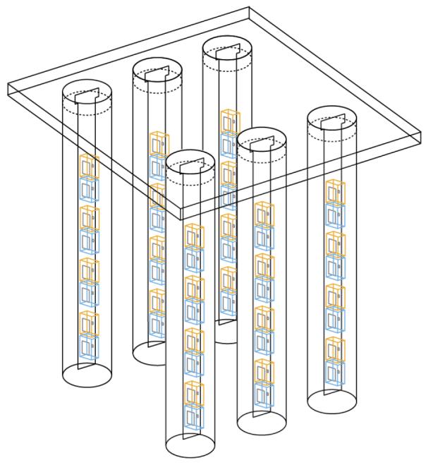
Schematic of a setup that enables 3-D arrays of yellow and blue LEDs to activate, silence, and resculpt neural activity in arbitrary 3-D patterns. The device is a 2-D array made of 1-D LED-bearing probes, each of which has alternating blue and yellow LEDs going down its length. The 1-D probes are placed in glass capillaries to prevent brain heating. The capillaries are then arranged in a 2-D array by placing them in form-fitting holes within a plastic plate.
3.4 3-D LED arrays: simulation of LED light penetration into the brain
As noted above, the efficacy of optical activation varies across 3 log units of power, from almost no stimulation at 0.1 mW/mm2, to near-maximal stimulation at 10 mW/mm2. Accordingly, we implemented a computational model that would let us rapidly estimate the power at various distances from blue and yellow LEDs embedded in the brain, aiming for an accuracy level better than a fraction of a log unit. We first performed Monte Carlo simulations of how light emitted from blue and yellow LEDs would be absorbed or scattered in the brain. We modeled 300 μm × 300 μm blue (460 nm) and yellow (590 nm) LEDs, placed on the surface of a cube of brain gray matter 4 millimeters on a side (Fig. 5Ai, 5Aii). We performed our Monte Carlo simulation by dividing the cube of gray matter into a 200 × 200 × 200 grid of voxels, each 20 μm × 20 μm × 20 μm in dimension. (We tested a subset of the models with 10 μm × 10 μm × 10 μm voxels, and obtained identical results, proving our resolution sufficient.) We interpolated data from reference 17 to obtain scattering coefficients for brain gray matter of 10 mm−1 for blue light and 9 mm−1 for yellow light, and to obtain absorption coefficients of 0.07 mm−1 for blue light and 0.027 mm−1 for yellow light. Since we were interested in light propagation close to the LED, before the orientation of photon trajectories is randomized by multiple scattering events, we used an anisotropic scattering model based upon the Henyey-Greenstein phase function, utilizing anisotropy parameters of 0.88 for blue light and 0.89 for yellow light17,18. We launched 106 packets of photons in a Lambertian radiation pattern from random points on the luminous surface of the LED, and modeled their propagation based on the algorithm of ref.17. In essence, whenever a photon packet entered a voxel, our program would probabilistically calculate the forecasted traveling distance before the next scattering event. If that traveling distance took the photon packet out of the starting voxel, then the packet would be attenuated appropriately for the distance it traveled within the starting voxel, and the process would then restart upon entry of the photon packet into the new voxel. If that traveling distance ended the trip of the photon packet within the starting voxel, then the packet would be attenuated appropriately for the distance it traveled within the starting voxel, and a new direction of packet propagation would be randomly chosen according to the Henyey-Greenstein function. Using this model, we generated Fig. 5, which shows the contours at which the light intensity falls off to 10%, 1%, and 0.1% of the intensity of light at the surface of the LED, for blue and yellow light respectively.
Fig. 5.

Monte Carlo simulations of how blue (left) and yellow (right) photons travel through the brain from LEDs (represented by colored lines to the right of the square). Shown are squares representing 4 mm × 4 mm cross-sections taken through the 4 mm × 4 mm × 4 mm cube simulated; the cross-sections are taken by slicing the cube through the LED center. Contours represent cross-sections of the surfaces at which the radiant flux drops to 10%, 1%, or 0.1% of their values on the LED surface.
To make these model results concrete, consider LEDs such as the 280 μm × 280 μm blue (460 nm) C460EZ290-S2400 LED from Cree19, and the 305 μm × 305 μm yellow (590 nm) HWFR-B317 LED from Lumileds20. The blue LED has a 1% contour envelope that resembles an ellipse 1.6 mm long and 1.4 mm wide; at a peak power of 24 mW, the 1% contour equates to ∼3 mW/mm2 radiant flux – an intensity easily sufficient to activate ChR2. Similarly, for the yellow LED, the 1% contour envelope resembles an ellipse 1.7 mm long and 1.5 mm wide, which at its peak power of 86 mW equates to a radiant flux of ∼15 mW/mm2 for yellow light, an intensity sufficient to activate the majority of Halo molecules. Of course, to illuminate smaller volumes, the light power can always be decreased. Thus, our model indicates that standard 300-micron LEDs should be able to illuminate brain volumes across a broad scale, all the way from cubic microns to several cubic millimeters.
We had set out to make a computational model that would estimate the power at various distances away from the LED, with accuracy significantly better than a log unit. We assessed the quality of our model by taking pictures, on a CCD camera, of the aforementioned blue and yellow LEDs (running at ∼100 microwatts power), through cortical slices of increasing thickness (150, 350, and 550 microns). We experimentally measured the diameter of the contour circle at which the light intensity falls off to 10% of the intensity of light at the surface of the LED. We then took the ratio of this diameter to the diameter of the contour computed via the Monte Carlo model, in a plane a comparable distance away from the LED and parallel to the LED front surface. This ratio came out to 0.74 ± 0.33 (mean ± standard deviation; n = 4 LED-slice thickness combinations), indicating that our model is accurate to the specifications desired. We repeated this comparison for the 1% contours and found the ratio to be 0.73 ± 0.06 (n = 5 LED-slice thickness combinations). There was a trend for the images to be somewhat dimmer than the model would predict. It is possible that vast uncertainty in tissue parameters, which is a subject of ongoing debate in the literature17, underlies some of this variability. In addition, natural brain heterogeneity may also explain the small differences between our data and our model (which assumes purely one kind of gray matter).
3.5 3-D LED arrays: fabrication and testing of the 1-D probe
Arranging 1-D probes in a 2-D array is not difficult, as shown in Fig. 4: almost any plate with appropriate holes will do to organize the 1-D probes into an array. The 1-D probe itself, though, requires some cleverness in order to fit all the components into a small enough glass capillary to avoid causing much damage upon insertion into the brain. Fig. 6A shows how we make this critical subcomponent, the 1-D probe, which acts as the fundamental building block of the 3-D probe. We solder 460 nm blue and 590 nm yellow LEDs (the same parts as modeled above, in Section 3.4), ∼300 microns on a side, to a 25-micron thick sheet of silver trimmed to be 650 microns wide. The silver sheet acts as a ground plane for the LEDs, and attaches, via a layer of insulating epoxy, to an underlying 25-micron thick aluminum sheet. The aluminum sheet is patterned, using an ultraviolet excimer laser, to have separate control traces for delivering power to each LED independently. Each LED is attached to a unique control trace on the aluminum sheet, via wire bonding. The entire device (Fig. 6C) is then placed into a thin (<1 mm diameter) glass capillary tube (not shown, for clarity). The control traces connect to a cable that leads out of the glass capillary, to an 8-channel LED driver circuit (Fig. 6B), for optimally driving the yellow and blue LEDs. The ends of the glass capillary are sealed with a biocompatible epoxy, thus sealing in an insulting layer of air between the LED probe and its glass capillary housing. These glass capillaries can then be inserted into holes in a plastic square, resulting in a 2-D array of the 1-D probes. We control the LED driver circuit with a PIC microcontroller (Fig. 6B), which talks over a USB port to a PC running MATLAB, thus allowing pulse sequences to be uploaded to the PIC in real time without necessitating complete reprogramming of the chip.
Fig. 6.

A, schematic of a 1-D LED probe, the basic building block of the 3-D array schematized in Fig. 4, expanded for ease of seeing how the probe is constructed. B, LED driver circuit, made of op-amps, load drivers, and a microcontroller. C, From top to bottom: picture of whole 1-D LED probe, zoomed-in picture of the LED part of the probe, zoomed-in picture of the LED part of the probe with one blue LED on, zoomed-in picture of the LED part of the probe with one yellow LED on.
Although for central nervous system applications, we utilize the 1-D LED probe shown in Fig. 6 as part of a larger 3-D system (schematized in Fig. 4), the device shown in Fig. 6 represents an extraordinarily flexible building block for getting light into the nervous system effectively, safely, and inexpensively. In our process, LEDs are simply placed on thin sheets of metal (which can be curved if desired), and the 1-D probes can be made as long or as short as one desires, using the rapid-prototyping tools here described. Accordingly, optical cochlear prostheses, vestibular prostheses, and peripheral nerve prostheses may be rapidly deployed using the design schema outlined in Fig. 4 and fulfilled in Fig. 6. Although the above optical probe is as small or smaller than comparable human devices (e.g., DBS electrodes), we are now engineering even smaller versions capable of controlling neurons in animals as small as a juvenile mouse.
3.6 Primate data: optically-elicited spike trains from primate cortex
In order to translate this precise optical neural control technology to humans, we must test its feasibility and safety in non-human primates, whose brains and other bodily systems more closely resemble ours than do those of rodents. As a test case, we prepared a male rhesus macaque for cortical recording in the frontal eye field (FEF) area of cortex, as predicted by MRI scans and validated with electrophysiology. We then surgically injected 1-4 μL of virus expressing ChR2-GFP under the CaMKII promoter into a site within FEF, using the same equipment as used in Section 2.2. We then waited 2 weeks for the virus to express, and then inserted a polished, 200 micron-thick optical fiber whose other end was fiber-coupled to a 200 mW blue (473 nm) laser, as described in Section 3.2. After optimizing the recording, we activated the laser to fire brief pulses of blue light by delivering 10 ms-long TTL pulses separated by 20 ms pauses (i.e., 33.3 Hz stimulation), and elicited trains of well-timed spikes (Fig. 7). This result demonstrates, for the first time, that both the genetic targeting of neurons, and the use of light to activate them, can work successfully in the macaque cortex, a key translational milestone along the road to human use.
Fig. 7.

Raster plots indicate occurrences of spikes (black dots) elicited from an excitatory neuron expressing ChR2 in the monkey cortex, in 22 consecutive spike trains (each shown as a row of black dots) elicited in response to a brief train of blue light stimulation. Each horizontal row reflects one recording of the response to five blue pulses of light (shown as blue dashes), each lasting 10 ms and separated from the next by 20 ms (i.e., 33.3 Hz stimulation rate).
4. CONCLUSIONS
We have demonstrated effective viral targeting of excitatory neurons in the intact brain. We have also revealed for the first time a novel, practical, 3-D LED array probe capable of being inserted into the brain for the purpose of activating or silencing circuits in a targeted way. This device is capable of activating and silencing neurons at the scale of microns to millimeters, and is inexpensive, reliable, and easy to use. Our device rides modern optics technology development curves, bolstered by progress in the arenas of displays and telecommunications, which have yielded small, high-power LEDs and rapid-prototyping equipment for the creation of miniaturized optical devices. We have also demonstrated for the first time that optical neural control technologies are capable of working in the intact primate brain, a major milestone in the quest to enable novel human therapies. The primate brain is much more similar to the human brain, in almost every regard, than is the rodent brain. Accordingly, both for safety and efficacy testing, and for animal model development, the primate may represent a natural pre-clinical testbed for optical neural control technologies.
In the future, we hope to use these technologies to understand how to control neural circuits to compensate for the loss or alteration of specific cell types, as often occur in neurological and psychiatric diseases ranging from obesity, to pain, to Parkinson's, to epilepsy. Neural control technologies such as DBS and TMS are increasing in popularity for the treatment of a great number of diseases, but because their mechanisms of therapeutic action are poorly understood, few generalized strategies or principles have emerged governing the design of treatments that use these technologies. By explicitly seeking out neural targets and activity patterns that enable control of neural circuits, we will develop a better understanding of the principles governing the correction of deficits at the neural-circuit level.
We will pursue the exploration of these technologies in a translational sense, to see if they may directly serve to enable cell- and circuit-level control in human patients of neurological and psychiatric disorders. Over 600 patients have been treated with genes delivered into their cells via the adeno-associated virus (AAV) vector, in 48 separate trials, without a single serious adverse event resulting from the virus21. AAV is ubiquitous (perhaps 90% of people have been exposed to it) and causes no symptoms by itself. Accordingly, we believe that the field of gene therapy is moving in directions that could make optical prosthetics highly beneficial and practical at some point in the not-so-distant future. Furthermore, the fact that ChR2 and Halo may be useful for controlling many neural circuits throughout the nervous system may simplify the exploration of this gene therapy space: once these molecules have been tested for basic efficacy and safety in a few kinds of neuron, subsequent validation attempts may proceed quite rapidly, for use in novel cell types.
6. ACKNOWLEDGMENTS
We thank the members of the MIT Neuromedia Group for helpful comments and advice. E. S. B. was supported by the NIH Director's New Innovator Award, the Benesse Corporation Foundation, the Jerry Burnett Foundation, the Society for Neuroscience Research Award for Innovation in Neuroscience, the MIT Media Lab Things That Think and Digital Life Consortia, the McGovern Institute Neurotechnology Program, the Wallace H. Coulter Foundation, the MIT Media Lab, the MIT School of Architecture, and the MIT McGovern Institute, as well as four private donors to the MIT Neurotechnology Fund. X. H. was supported by a Helen Hay Whitney Fellowship. M. A. H. was supported by a Hugh Hampton Young Fellowship. J. G. B., J. P. M., and E. Y. K. were supported in part by the MIT Undergraduate Research Opportunities Program.
REFERENCES
- 1.Bernard C, Anderson A, Becker A, et al. Science. 2004;305(5683):532. doi: 10.1126/science.1097065. [DOI] [PubMed] [Google Scholar]; Sanabria ER, Su H, Yaari Y. J Physiol. 2001;532(Pt 1):205. doi: 10.1111/j.1469-7793.2001.0205g.x. [DOI] [PMC free article] [PubMed] [Google Scholar]; Shao LR, Dudek FE. J Neurophysiol. 2004;92(3):1366. doi: 10.1152/jn.00131.2004. [DOI] [PubMed] [Google Scholar]; Houser CR, Miyashiro JE, Swartz BE, et al. J Neurosci. 1990;10(1):267. doi: 10.1523/JNEUROSCI.10-01-00267.1990. [DOI] [PMC free article] [PubMed] [Google Scholar]
- 2.Buckmaster PS, Dudek FE. J Comp Neurol. 1997;385(3):385. [PubMed] [Google Scholar]
- 3.Lewis DA, Hashimoto T, Volk DW. Nat Rev Neurosci. 2005;6(4):312. doi: 10.1038/nrn1648. [DOI] [PubMed] [Google Scholar]
- 4.George MS, Wassermann EM, Williams WA, et al. Neuroreport. 1995;6(14):1853. doi: 10.1097/00001756-199510020-00008. [DOI] [PubMed] [Google Scholar]; Pascual-Leone A, Rubio B, Pallardo F, et al. Lancet. 1996;348(9022):233. doi: 10.1016/s0140-6736(96)01219-6. [DOI] [PubMed] [Google Scholar]; Mayberg HS, Lozano AM, Voon V, et al. Neuron. 2005;45(5):651. doi: 10.1016/j.neuron.2005.02.014. [DOI] [PubMed] [Google Scholar]
- 5.Groves DA, Brown VJ. Neuroscience and biobehavioral reviews. 2005;29(3):493. doi: 10.1016/j.neubiorev.2005.01.004. [DOI] [PubMed] [Google Scholar]; Fountas KN, Smith JR, Murro AM, et al. Stereotactic and functional neurosurgery. 2005;83(4):153. doi: 10.1159/000088656. [DOI] [PubMed] [Google Scholar]; Morrell M. Current opinion in neurology. 2006;19(2):164. doi: 10.1097/01.wco.0000218233.60217.84. [DOI] [PubMed] [Google Scholar]
- 6.Rasche D, Rinaldi PC, Young RF, et al. Neurosurgical focus. 2006;21(6):E8. doi: 10.3171/foc.2006.21.6.10. [DOI] [PubMed] [Google Scholar]; Tasker RR, Vilela Filho O. Stereotactic and functional neurosurgery. 1995;65(1-4):122. doi: 10.1159/000098682. [DOI] [PubMed] [Google Scholar]
- 7.Benabid AL, Pollak P, Louveau A, et al. Applied neurophysiology. 1987;50(1-6):344. doi: 10.1159/000100803. [DOI] [PubMed] [Google Scholar]; Iacono RP, Lonser RR, Maeda G, et al. Acta neurochirurgica. 1995;137(1-2):106. doi: 10.1007/BF02188792. [DOI] [PubMed] [Google Scholar]; Pahwa R, Wilkinson S, Smith D, et al. Neurology. 1997;49(1):249. doi: 10.1212/wnl.49.1.249. [DOI] [PubMed] [Google Scholar]; Kumar R, Lozano AM, Kim YJ, et al. Neurology. 1998;51(3):850. doi: 10.1212/wnl.51.3.850. [DOI] [PubMed] [Google Scholar]; Lopiano L, Rizzone M, Bergamasco B, et al. Neurology. 2001;56(4):552. doi: 10.1212/wnl.56.4.552. [DOI] [PubMed] [Google Scholar]; Benabid AL, Krack PP, Benazzouz A, et al. Neurology. 2000;55(12 Suppl 6):S40. [PubMed] [Google Scholar]
- 8.Leone M. Lancet Neurol. 2006;5(10):873. doi: 10.1016/S1474-4422(06)70575-0. [DOI] [PubMed] [Google Scholar]
- 9.Penfield W, Rasmussen T. The Cerebral Cortex of Man: A Clinical Study of Localization of Function. Macmillian; 1950. [Google Scholar]
- 10.Rosebush PI, Mazurek MF. Neurology. 1999;52(4):782. doi: 10.1212/wnl.52.4.782. [DOI] [PubMed] [Google Scholar]; Herranz JL, Armijo JA, Arteaga R. Epilepsia. 1988;29(6):794. doi: 10.1111/j.1528-1157.1988.tb04237.x. [DOI] [PubMed] [Google Scholar]; McElroy SL, Keck PE, Jr., Friedman LM. The Journal of clinical psychiatry. 1995;56(Suppl 2):49. [PubMed] [Google Scholar]
- 11.Boyden ES, Zhang F, Bamberg E, et al. Nat Neurosci. 2005;8(9):1263. doi: 10.1038/nn1525. [DOI] [PubMed] [Google Scholar]
- 12.Han X, Boyden ES. PLoS ONE. 2007;2:e299. doi: 10.1371/journal.pone.0000299. [DOI] [PMC free article] [PubMed] [Google Scholar]
- 13.Bischofberger J, Engel D, Li L, et al. Nature protocols. 2006;1(4):2075. doi: 10.1038/nprot.2006.312. [DOI] [PubMed] [Google Scholar]
- 14.Womelsdorf T, Fries P, Mitra PP, et al. Nature. 2006;439(7077):733. doi: 10.1038/nature04258. [DOI] [PubMed] [Google Scholar]
- 15.Dittgen T, Nimmerjahn A, Komai S, et al. Proc Natl Acad Sci U S A. 2004;101(52):18206. doi: 10.1073/pnas.0407976101. [DOI] [PMC free article] [PubMed] [Google Scholar]
- 16.Wang H, Peca J, Matsuzaki M, et al. Proc Natl Acad Sci U S A. 2007;104(19):8143. doi: 10.1073/pnas.0700384104. [DOI] [PMC free article] [PubMed] [Google Scholar]
- 17.Yaroslavsky AN, Schulze PC, Yaroslavsky IV, et al. Physics in medicine and biology. 2002;47(12):2059. doi: 10.1088/0031-9155/47/12/305. [DOI] [PubMed] [Google Scholar]
- 18.Binzoni T, Leung TS, Gandjbakhche AH, et al. Physics in medicine and biology. 2006;51(17):N313. doi: 10.1088/0031-9155/51/17/N04. [DOI] [PubMed] [Google Scholar]
- 19.Cree 2007. CPR3CQ.pdf, Available at http://cree.com/products/PDF/CPR3CQ.pdf.
- 20.Lumileds 2007. DS42.PDF, Available at http://lumileds.com/pdfs/DS42.PDF.
- 21.Nat Biotechnol. 2007;25(9):949. doi: 10.1038/nbt0907-949. [DOI] [PubMed] [Google Scholar]