Abstract
Measurement of human posture and movement is an important area of research in the bioengineering and rehabilitation fields. Various attempts have been initiated for different clinical application goals, such as diagnosis of pathological posture and movements, assessment of pre- and post-treatment efficacy and comparison of different treatment protocols. Image-based methods for measurements of human posture and movements have been developed, such as the radiography, photogrammetry, optoelectric technique and video analysis. However, it is found that these methods are complicated to set up, time-consuming to operate and could only be applied in laboratory environments. This study introduced a method of using a posture monitoring system in estimating the spinal curvature changes during trunk movements on the sagittal and coronal planes and providing trunk posture monitoring during daily activities. The system consisted of three sensor modules, each with one tri-axial accelerometer and three uni-axial gyroscopes orthogonally aligned, and a digital data acquisition and feedback system. The accuracy of this system was tested with a motion analysis system (Vicon 370) in calibration with experimental setup and in trunk posture measurement with nine human subjects, and the performance of the posture monitoring system during daily activities with two human subjects was reported. The averaged root mean squared differences between the measurements of the system and motion analysis system were found to be <1.5° in dynamic calibration, and <3.1° for the sagittal plane and ≤2.1° for the coronal plane in estimation of the trunk posture change during trunk movements. The measurements of the system and the motion analysis system was highly correlated (>0.999 for dynamic calibration and >0.829 for estimation of spinal curvature change in domain planes of movement during flexion and lateral bending). With the sensing modules located on the upper trunk, mid-trunk and the pelvic levels, the inclination of trunk segment and the change of spinal curvature in trunk movements could be estimated. The posture information of five subjects was recorded at 30 s intervals during daily activity over a period of 3 days and 2 h a day. The preliminary results demonstrated that the subjects could improve their posture when feedback signals were provided. The posture monitoring system could be used for the purpose of posture monitoring during daily activity.
Keywords: Tri-axial accelerometer, Gyroscope, Posture monitoring, Motion analysis, Spine
Introduction
Radiographical method is generally used for assessing spinal curvature. However, it is relatively invasive and cannot provide continuous information in dynamic situations. Therefore, alterative methods have been evolved. Optoelectronic motion analysis is an example for measuring trunk movements and spinal curvature changes and its capability of producing repeatable measurement of trunk movement has been documented [3, 6, 15–17]. Nonetheless, this technique may require a large space for setup and the data capture is confined within laboratory or clinical environment and could provide a short-term measurement only. The trunk motion analysis is limited to some standard procedures and cannot be extended to daily activities.
Some motion analysis systems are relatively portable, such as electromagnetic tracking systems and potentiometric goniometers, also have been used for clinical and research purposes. Electromagnetic tracking systems are three-dimensional measurement devices and have been used in human posture and movement analysis. The systems consist of transmitter and receivers, which generating a low-frequency magnetic field and detecting the magnetic field, respectively. The positions and orientations of the receivers relative to the transmitter can be calculated by the system. Such systems were available commercially and used for kinematics studies in spinal movements [2, 7, 12, 15]. However, the accuracy of the measurement is affected by the distance between the transmitter and receivers, and also can be adversely affected by the presence of metallic object. It cannot be used for taking measurements in some activities (e.g. walking, lifting) due to the restricted operational zone. Besides, it also may not be suitable for the patient with metallic implants and prostheses, and the experimental environment should be free from metallic object.
Potentiometric goniometers have been used to measure spinal curvature and motion in clinical and research applications. In general, a potentiometric goniometer is a linkage device with a number of precision potentiometers connected by a series of metal bars, for acquisition of coordinates in three-dimensional space. The potentiometric goniometers have been used to assess the mobility of the lumbar spine during three-dimensional spinal movements [13, 15]. However, bulkiness of the goniometer may limit its application for continuous assessment of spinal movements during daily activities, recreational activities and occupational task.
In the recent decade, various inertial sensors have been developed for robotic, industrial and aerospace and biomedical applications. These sensors become smaller in size and better in performance owing to the advanced circuit technology [5]. Accelerometers and gyroscopes are commonly used to provide information on position and orientation in aerospace and robotic industries. For biomechanical analysis, these sensors can also be used to measure tilting angle relative to the gravity and linear acceleration, and angular velocity of the body segments. Therefore, portable motion analysis systems could be built with these miniaturized sensors.
Analyses of trunk orientation relative to other body segments using accelerometers and gyroscopes have been demonstrated [8, 11, 14]. However, the feasibility of using accelerometers and gyroscopes for collecting postural information related to the spinal surface profile and the performance in the posture monitoring during daily activities has not been widely investigated and reported in literatures. The aim of this study is to introduce a method of using tri-axial accelerometers and gyroscopes to detect postural change in terms of curvature variation of the spine on the sagittal and coronal planes and demonstrate the performance of the posture monitoring system during daily activities.
Methods
Equipments
Three equipments were used in this study, including (a) a three-dimensional video-base motion analysis system, (b) sensing system with three sensor modules, and (c) a portable posture monitoring system. The motion analysis system and the sensing system (a, b) were used to collect the data in static and dynamic calibration and estimation of spinal curvature change, and the measurements were compared accordingly, and a posture monitoring system (c) was used in trunk posture monitoring:
A three-dimensional video-base motions analysis system with six cameras with infra-red light source (Vicon 370) was used to monitor the three-dimensional coordinates of the retro-reflective markers with 60 Hz sampling rate. The Vicon system was considered to have an accuracy of <1° and <1.5° root mean square in static and dynamic angular measurements, respectively.
Sensing system, consisted of three sensor modules with inertial sensors, was developed to measure trunk movements on the sagittal and coronal planes. Each sensor module (size: 22 mm × 20 mm × 12 mm, weight: 6 g) consisted of a tri-axial accelerometer (KXM52-Tri-axis, Kionix) and three uni-axial gyroscopes (Epson) orthogonally aligned, and assembled in a quasi-rectangular box. The sensor modules connected to an interface board with power supply and adapter for connection of an “Analog to Digital” converter of the motion analysis system for data collection.
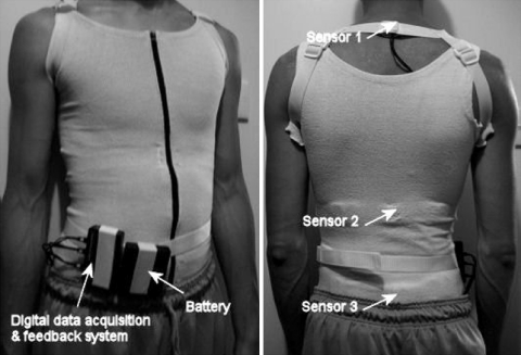
Posture monitoring system consisted of three sensor modules, a digital data acquisition and feedback system, battery pack and a garment. The three sensor modules of the sensing system were integrated into the tight fit and elastic garment and connected to the digital data acquisition and feedback system. The data acquisition and feedback system (size: 21 mm × 50 mm × 84 mm, weight: 44.5 g) consisted of microcontrollers, memory with associated circuit and buzzer, was packaged into a plastic box. The system operated with four AAA size rechargeable batteries (Ni-MH type, 1,100 mAh, 1.2 V), which packaged in a battery holder (size: 50 mm × 55 mm × 12 mm, weight: 82 g) and requires recharging after 8 h operation.
Auto-reset algorithm
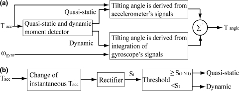
An auto-reset algorithm was applied with the signals of accelerometer and gyroscope to calculate the orientation of sensor modules along x and y axes of the sensor modules. The orientation of the sensor modules was calculated by integration of the gyroscope signal during dynamic conditions and tilting angle derived from signals of accelerometers at quasi-static conditions (see Appendix).
Error estimation of tilting measurement
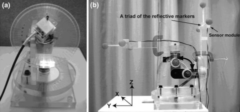
The accuracy and the reliability of sensor modules for static tilting measurement were evaluated using a three-dimensional rotation alignment device (Fig. 1a). The alignment device can provide actual tilting angle with 1° increment. A sensor module was fixed on the device as shown in Fig. 1a. The testing range was from ±90° for the x and y axes. The sensor module was tilted along the x-axis with 5° interval in testing range and with pre-tilted angle along the y-axis, and vice versa (Fig. 1a). The pre-tilted angles were set as an interval of 20° in the range of ±60° along the x and y axes. Three sets of measurement of each sensor module were collected. The error analysis of the measurement was tested in terms of root mean square error and correlation coefficient. The reliability of measurement of the sensor modules was tested using the interclass correlation coefficient method, ICC (3,1).
Fig. 1.
Experimental setting for a static tilting, b dynamic tilting measurements
In dynamic tilting measurement, the performance of the posture measurement system with and without auto-reset algorithm for orientation measurement was evaluated using the motion analysis system along the x and y axes. The experimental setup consisted of tilting platform and a triad with three reflective markers (Fig. 1b). The orientation of reference coordinate system was derived from the three-dimensional coordinates of three reflective markers of a triad. The sensor module was affixed and aligned on the triad with the axis of the reference coordinate system. The tilting platform was tilted along the x and y axes manually in five tilting cycles with range of 90° for five trials.
Trunk posture measurement
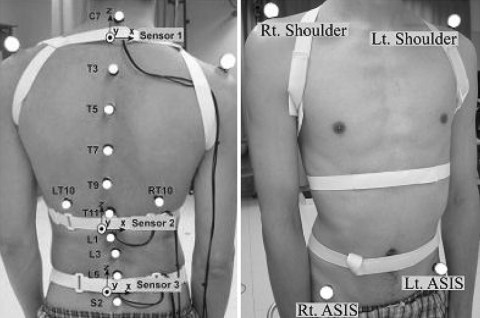
Three inertial sensor modules of the sensing system were attached onto the back of the subjects at the upper trunk (T1/T2), middle trunk (T12) and pelvic (S1) levels with elastic straps and 16 reflective markers were attached on the back, shoulders and pelvis of the subjects for testing as shown in Fig. 2.
Fig. 2.
Locations of reflective markers and sensor modules
The postural change of left and right lateral bending (LB & RB), forward flexion (FE) (rounding of the lumbar spine to a “slouched” seated posture) from neutral sitting position (upright sitting), and stand-sit-stand (STSI) on the sagittal and coronal planes in thoracic, lumbar regions were assessed simultaneously, using the sensing system and motion analysis system (Vicon 370) in nine subjects (three men and six women, age: 23.3 ± 2.5 years, weight: 55.4 ± 8.5 kg, height: 1.60 ± 0.08 m and BMI: 20.6 ± 2.9 kg m−2.) who were without back injury and spinal deformity. Written informed consents were obtained from all subjects prior to the experiments. Each trunk movement was performed for three trials. For each trial, the subject would sit still in an upright position at the first 2 s of the measurement as an initial reference period in order to initialise the inclination angle and offset the reading of the sensors.
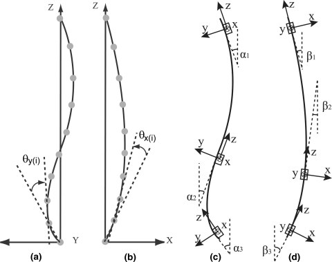
The trunk postural changes on the sagittal and coronal planes were estimated by the data from both the motion analysis system and the sensing system with three sensor modules (Fig. 3) (see Appendix). The output signals of the sensing system were manipulated with the auto-reset algorithm to estimate the postural change, in terms of curvature alteration measured between adjacent sensor modules and defined based on the concept of calculating the change of inclination angles difference between upper trunk and middle trunk for thoracic spine and between middle trunk and pelvis for lumbar spine in different postures [9], and the angular measurements were compared with that taken by the motion analysis system. For the data from the motion analysis system, the posture change was defined as total of changes of inter-segmental angles in the thoracic and lumbar regions separately, which was derived from every 3 consecutive markers on the sagittal and coronal planes. Kinematic parameters, including the angular velocity of the trunk movements and peak value of the trunk postural change were calculated from the data of the motion analysis system and documented for reference. The angular velocity of the trunk movements was defined as the angular velocity of the projection of the line formed by the C7 and the sacrum (S2) on the sagittal and coronal plane. The sign of angle was adopted as flexion and lateral bending to right were considered to be positive, and movement in opposite directions were represented by negative value for all data. All the signals from both the motion analysis system and the sensing system were filtered with a fifth-order zero-phase Butterworth low-pass filter with cutoff-frequency of 4 Hz to remove noise from all the raw data.
Fig. 3.
Trunk postural change calculated with the data of the motion analysis system was defined by the total change of inter-segmental angles (θx,y(i)), which was formed with three consecutive retro-reflective markers on a the sagittal and b coronal planes and the sensing system was defined by the change of inclination differences between angles αi and βi , respectively, formed by the tangent and vertical line on c sagittal and d coronal planes
Trunk posture monitoring
Five subjects (four female and five male, age: 25.2 ± 4.8 years, weight: 50.5 ± 7.2 kg, height: 1.7 ± 0.09 m and BMI: 18.4 ± 1.1 kg m−2) used the posture monitoring system in 3-day trials during daily activities with different protocols (Table 1). Written informed consents were obtained from both subjects prior to the experiments. Subjects carried the posture monitoring system with the integrated garment and a belt during this study (Fig. 4). The system monitor the trunk posture change based on the concept of the trunk posture measurement in previous session. It was calibrated in neutral standing position for 1 min before starting the posture monitoring. The rationale of the posture monitoring system for posture training is by keeping the tone off for as long as the user can, the users will learn which postures will keep the back in their nature spinal curvature in neutral standing position. Eventually, maintaining the nature spinal curvature (good posture) more often as their posture habit. The rationale was explained to the subject in detail, but the protocol was not known by the subjects to prevent the bias. Feedback was provided in form of sound from a buzzer for five times (about 2 s) while the measured changes of trunk posture (trunk angles) at thoracic and lumbar regions from neutral standing position was out of the target range (for controlling flexion only on the sagittal plane, but both sides bending on the coronal plane) and last for longer than the specified tolerance time according to the protocol (Table 1). The recording rate was set at two sets of measurements per minute. The recorded data included the tilting angles of the sensor modules and trunk angles of the thoracic and lumbar regions. All subjects used the system for 2 h per day in this study. The trunk angles between 3-day trials were tested using repeated measures ANOVA.
Table 1.
Protocol of trunk posture monitoring
| Day | Feedback status | Target range | Tolerance time | |
|---|---|---|---|---|
| Sagittal plane | Coronal plane | |||
| 1 | OFF | – | – | – |
| 2 | ON | <10° | ±10° | 1 min |
| 3 | ON | <5° | ±5° | 1 min |
Fig. 4.
Subject with the posture monitoring system
Results
Error estimation of tilting measurements
The RMS error of the sensor modules is ≤1°, correlation coefficients and the ICC coefficients are >0.999 for the static measurement of couple-tilting angle in the range of ±90° with pre-tilted angle in the range of ±60°.
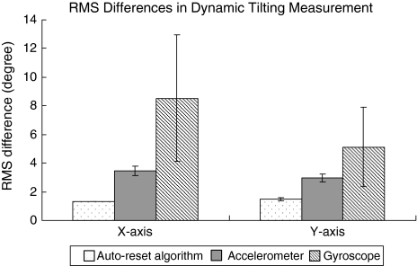
In the dynamic tilting measurement, the averaged RMS differences between the measurements of the sensing system and motion analysis system are ≤1.5° and the correlation coefficients are >0.999 for the measurements in the range of ±90° and with RMS angular velocity <40 deg s−1 along the X and Y axes. The averaged RMS differences of the auto-reset algorithm are less than those of the accelerometer and gyroscope (Fig. 5).
Fig. 5.
The averaged RMS difference of the sensor modules and motion analysis system in the dynamic tilting measurement
Trunk posture measurement
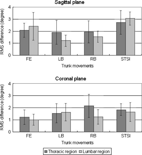
The averaged root mean squared (RMS) differences between the sensing system and the motion analysis system was found to be <3.1° for the sagittal plane and ≤2.1° for the coronal plane at all measured trunk regions and movements (Fig. 6). The correlation coefficients of the measurements are >0.829 for the measurement in domain planes of flexion and lateral bending (Table 2).
Fig. 6.
The averaged root mean squared (RMS) differences between the measurements of trunk posture change of the sensing modules and the motion analysis system in thoracic and lumbar regions during flexion (FE), left and right lateral bending (LB, RB), and stand-sit-stand (STSI)
Table 2.
Pearson correlation coefficients of the measurements between the sensing modules and motion analysis system, peak value and RMS angular velocity of the trunk movements (mean ± standard deviation)
| Trunk movements | Sagittal-dominated | Coronal-dominated | ||
|---|---|---|---|---|
| Flexion (FE) | Stand-sit-stand (STSI) | Left bending (RB) | Right bending (RB) | |
| Correlation coefficient | ||||
| Thoracic region | 0.983 ± 0.014 | 0.776 ± 0.168 | 0.941 ± 0.078 | 0.829 ± 0.308 |
| Lumbar region | 0.981 ± 0.014 | 0.966 ± 0.036 | 0.985 ± 0.009 | 0.984 ± 0.015 |
| Peak value (°) | ||||
| Thoracic region | 22.8 ± 11.1 | 16.3 ± 6.0 | 3.8 ± 1.5 | 3.8 ± 1.2 |
| Lumbar region | 24.7 ± 7.0 | 26.8 ± 6.2 | 6.1 ± 1.3 | 6.2 ± 2.2 |
| RMS angular velocity (deg s−1) | ||||
| Sagittal plane | 6.3 ± 3.0 | 6.6 ± 1.9 | 1.5 ± 0.4 | 1.4 ± 0.5 |
| Coronal plane | 1.0 ± 0.4 | 2.4 ± 1.0 | 4.4 ± 1.1 | 4.5 ± 1.3 |
Performance of trunk posture monitoring
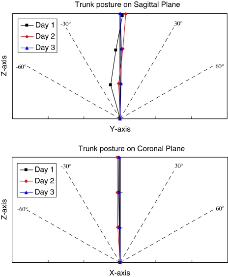
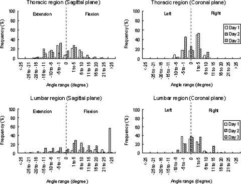
On the 3-days trials, the averaged trunk angles in thoracic and lumbar regions on the sagittal and coronal planes of the subjects are showed in Table 3. The trunk angle of the lumbar region on the sagittal plane was significant different between trials (P = 0.001) and was found to be significant smaller with provided feedback on day 2 and 3 than those without feedback on day 1 (P = 0.036, 0.003). Figure 7 shows the averaged trunk posture of the subject during trunk posture monitoring. Figure 8 shows the frequency distribution of the averaged trunk angles in the thoracic and lumbar regions on the sagittal and coronal planes of the subjects.
Table 3.
Trunk angles (mean ± standard deviation) of the thoracic and lumbar regions on the sagittal and coronal planes of the subjects
| Trials | Sagittal plane | Coronal plane | ||
|---|---|---|---|---|
| Thoracic region | Lumbar region | Thoracic region | Lumbar region | |
| Day 1 | 1.6 ± 4.2 | 23.1 ± 11.3 | 0.8 ± 3.2 | 0.2 ± 1.0 |
| Day 2 | −2.4 ± 7.3 | 8.2 ± 6.6 | 0.7 ± 1.6 | 2.5 ± 5.8 |
| Day 3 | −2.9 ± 3.3 | −0.7 ± 7.4 | 0.1 ± 3.7 | -0.4 ± 2.4 |
| P value | 0.360 | 0.001 | 0.799 | 0.568 |
Positive value represents flexion or right side bending, negative value represents extension or left side bending
Fig. 7.
Trunk postures of the subjects in 3-day trials
Fig. 8.
Frequency distributions of trunk angles in thoracic and lumbar regions on sagittal and coronal planes (sample size = 5)
Discussion
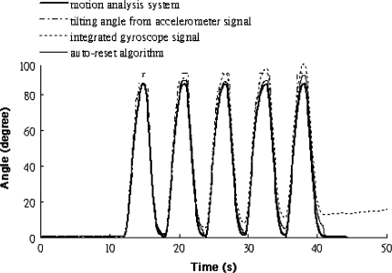
The measurements of the gyroscopes and accelerometers could drift and fluctuate respectively. An auto-reset algorithm was used to minimize the error of the measurement due to these problems. This auto-reset algorithm functioned with a “quasi-static and dynamic moments” detector was applied for deriving the angular measurements from the signals of gyroscopes and accelerometers in the dynamic and quasi-static conditions, respectively. In this study, the sensor modules was demonstrated to be able to detect the change of 1° in static tilting measurement that is comparable to the other studies [11, 14]. The drifts and fluctuations of the measurements in dynamic tilting measurement could be minimized via this algorithm (Fig. 9). In the estimation of the trunk posture, the measurement of using the sensor modules was found to be found to be highly correlated in dominant trunk movements of flexion and lateral bending, and reasonably close in magnitude to those of the optoelectronic motion analysis system. The correlation coefficient of the measurements at the thoracic region was relatively smaller during stand-sit-stand movement than those in other trunk movements. The stand-sit-stand movement is not formed with angular movements on the sagittal and coronal planes only, which also combined with transitional movement along the axis of the gravity. The measurement may be affected by the acceleration of this movement along the axis of the gravity. The postural change of the thoracic region was also found to be relatively smaller than those of the lumbar region. Therefore, the correlation coefficient could be affected by the noise of the signals. However, the results of this study demonstrated that use of three sensor modules could estimate the change of the spinal profile curvature of the trunk.
Fig. 9.
The performance of the auto-reset algorithm
For the 3-day trials with the posture monitoring system, all subjects reported that they were sitting more often than standing during monitoring period. The change of the trunk angles was more obvious on the sagittal plane than coronal plane. The averaged value of the trunk angles on sagittal plane was smaller on the day 2 and 3 than on the day 1. This might be due to the subjects straightening their spine more often with the feedback signals. It is found that the trunk angles were kept more frequent within the target range according to the protocol. The result showed that the subjects tried to keep their trunk in extension more often in day 2 and 3 and they reported that they were sitting with the backrest of the office chair more often in these two days. The preliminary results demonstrated that the subjects could improve their posture when feedback signals were provided. However, the effectiveness of the posture monitoring system in posture training should be verified in long-term clinical trials.
The trunk rotation motion on the transverse plane could not be estimated using the sensing system of the posture monitoring system in this current study because the accelerometer signals cannot provide the information about the motion on that plane to the auto-reset algorithm for estimation of the orientation of the sensor module. The possible solution of this problem is made use of the magnetic sensor to provide reference information, which sensing the magnetic flied of the earth, to auto-reset algorithm to correct the drifting problem of gyroscope signal [8, 18]. The 3DOF orientation tracker (MTX, Xsens Technology B.V) (size: 38 × 53 × 21 mm and weight: 30 g) has been developed with this technique for orientation measurement of human body segments, which can provide kinematic data, including 3D acceleration, 3D rate of turn and 3D earth-magnetic field. However, the measurement of the tracker will be affected at a magnetic environment which can full immunity to temporary magnetic disturbances for 30 s, the average static error was 1.4° (standard deviation = 0.4) and the dynamic error was 2.6° root means square in the magnetically disturbed experiments [18]. Although the additional sensor can provide more information of spine motion, the enlargement of the size of the sensor module after adding the extra sensor should be considered as the practical issue for monitoring during daily activities.
The choice of measurement parameter is essential in designing a posture monitoring system and should be interpreted easily. Posture training devices for treatment of scoliosis were developed by monitoring instantaneous torso length [4] and asymmetry of shoulder and pelvic levels [1, 10] continuously. The measurement parameters of these devices are not directly related to the spinal curvature. In the current study, the choice of the measurement parameter was the change of the spinal profile curvature of the trunk. It is because the postural change of the trunk could be better interpreted in the spinal posture analysis and compared to the natural curvature of the spine via measuring curvature change instead of the other physical features.
Different numbers of sensors were used for monitoring and training people to improve trunk posture on the sagittal plane in literatures, including one [11] and six dual-axial accelerometers [14]. Use of one accelerometer was able to detect the trunk tilting but not curvature change because of lacking reference signals from the distal portion of the trunk. Although more sensors could provide more information about the orientation of the spine, a good design should balance the accuracy and practicality, and not to cause considerable deviation from daily activities. In this current study, the results verified the possibility of using three sensor modules to detect posture change in terms of spinal surface curvature change on the sagittal and coronal planes simultaneously in trunk movements.
Conclusion
In the development of the posture monitoring system, the orientation measurement and estimation of spinal surface curvature change using auto-reset algorithm were found to be highly correlated and reasonably close in magnitude to those of the motion analysis system. The system was developed to become a portable trunk posture analysis system and fixed to the body for tracking trunk posture change, and could be used for collecting the trunk posture information about daily postural habit of the users. The preliminary results demonstrated that the posture of normal subjects could be monitored and trained via this system.
Acknowledgments
This study was supported by the Research Committee of The Hong Kong Polytechnic University. The authors are grateful to Dr. Alan Lam, engineers of Sengital Limited and Prof. Daniel Chow for their technical support and advices.
Appendix
Mathematical section for auto-reset algorithm
 |
1 |
 |
2 |
where AccX, AccY and AccZ are signals of accelerometer, and Tacc is tilting angle derived from the signals of accelerometer.
 |
3 |
 |
4 |
where ωX, ωY and ωZare signals of gyroscopes, ωgyro are angular velocity.
 |
5 |
where Tangle is angle calculated with auto-reset algorithm (Fig. 10), S(t) is the rectified signals derived from the variation of the Tacc, t is the index of time, the value of N is 5 and the threshold is 1 which are derived from the experimental results.
Fig. 10.
a An auto-reset algorithm with b “quasi-static and dynamic moment detector” for calculation of the sensor orientation. Rectified signals S(t), which derived from the variation of the inclination derived from the accelerometer’s signals (Tacc), compared with the threshold to identify the condition is quasi-static or dynamic. The orientation of the sensor along the x and y axes (Tangle) was calculated from the integration of the gyroscope’s signals (ωgyro) at dynamic moment (condition) and the inclination derived from the accelerometer’s signals at quasi-static moment (condition)
Calculation of the trunk posture change (motion analysis system)
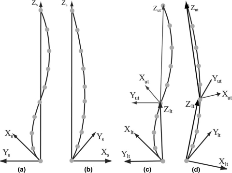
The parameters of the trunk posture measurement were calculated based on several axis systems, including thoracic axis system (Xut, Yut and Zut), lumbar axis system (Xlt, Ylt and Zlt), and spinal axis system (Xs, Ys and Zs). The X, Y and Z axes constructed a right-handed Cartesian coordinate system and point to the anatomical directions:
X to anatomical right side, Y to anatomical anterior direction, Z to anatomical superior.
The regional trunk posture change of thoracic and lumbar spine was calculated based on the thoracic and lumbar axis system. The sign of angle was adopted as flexion and lateral bending to right were considered to be positive, and movement in opposite directions were represented by negative value for all data. Kinematic parameters, including the peak value and angular velocity of the trunk movements and, were calculated from the data of the motion analysis system and were documented for reference. The angular velocity of the trunk movements was defined as the angular velocity of the projection of the line formed by C7 and the sacrum (S2) on the sagittal and coronal planes of the pelvic axis system.
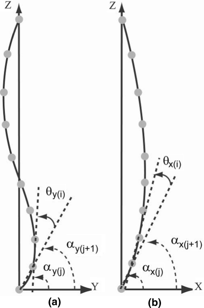
Inter-segmental angles (θi) is formed with three consecutive retro-reflective markers, where αj is the projection angle relative to y-axis and x-axis of the thoracic axis system for thoracic region and lumbar axis system for lumbar region on the sagittal plane and coronal plane, respectively (Figs. 11, 12).
Fig. 11.
Calculation of the trunk posture changes on (a, c) sagittal and (b, d) coronal planes during trunk movement
Fig. 12.
Calculation of the inter-segmental angles on a sagittal and b coronal planes during trunk movement
For sagittal plane,
 |
6 |
where y and r are y-coordinate and magnitude of the vector which formed with 2 consecutive markers respectively
 |
7 |
where θ and N is an inter-segmental angle and number of reflective markers at the subject’s back in the specific trunk region respectively
For coronal plane,
 |
8 |
where x and r are x-coordinate and magnitude of the vector which formed with 2 consecutive markers respectively
 |
9 |
where θ and N is an inter-segmental angle and number of reflective markers at the subject’s back in the specific trunk region respectively
Trunk angle (β) is a sum of total inter-segmental angles.
 |
10 |
where θ and N is an inter - segmental angle and number of reflective markers at the subject’s back in the specific trunk region respectively
The trunk posture changes (δ) during trunk movements on the sagittal and coronal planes were estimated by subtraction of the trunk angle at initial time (β0) from those at the spontaneous time (βT).
 |
11 |
References
- 1.Bazzarelli M, Durdle NG, Lou E, Raso J. A low power hybrid posture monitoring system. Elect Comput Eng. 2001;2:13–16. [Google Scholar]
- 2.Bull AMJ, McGregor AH. Measuring spinal motion in rowers: the use of an electromagnetic device. Clin Biomech. 2000;15:772–776. doi: 10.1016/S0268-0033(00)00043-7. [DOI] [PubMed] [Google Scholar]
- 3.Chockalingam N, Dangerfield P. Non-invasive measurements of scoliosis and the spine: a review of the literature. Int J Therapy Rehabil. 2003;10(12):554–562. [Google Scholar]
- 4.Dworkin B, Miller NE, Dworkin N. Behavioral method for the treatment of idiopathic scoliosis. Proc Nat Acad Sci. 1985;82:2493–2497. doi: 10.1073/pnas.82.8.2493. [DOI] [PMC free article] [PubMed] [Google Scholar]
- 5.Eddy DS, Sparks DR. Application of MEMS technology in automative sensors and actuator. Proc IEEE. 1998;86(8):1747–1755. doi: 10.1109/5.704280. [DOI] [Google Scholar]
- 6.Gracovetsky S, Newman N, Pawlowsky M, Lanzo V, Davey B, Robinson L. A database for estimating normal spinal motion derived from noninvasive measurements. Spine. 1995;20(9):1036–1046. doi: 10.1097/00007632-199505000-00010. [DOI] [PubMed] [Google Scholar]
- 7.Lee RYM. Kinematics of rotational mobilization of the lumbar spine. Clin Biomech. 2001;16:481–488. doi: 10.1016/S0268-0033(01)00036-5. [DOI] [PubMed] [Google Scholar]
- 8.Lee RYW, Laprade J, Fung EHK. A real-time gyroscopic system for three-dimensional measurement of lumbar spine motion. Med Eng Phys. 2003;25:817–824. doi: 10.1016/S1350-4533(03)00115-2. [DOI] [PubMed] [Google Scholar]
- 9.Lobel WY. Measurement of spinal posture and range of spinal movement. Ann Phys Med. 1967;9(3):103–110. doi: 10.1093/rheumatology/9.3.103. [DOI] [PubMed] [Google Scholar]
- 10.Lou E, Bazzarelli M, Hill D, Durdle N (2001) A low power accelerometer used to improve posture. In: Proceedings of the IEEE Canadian conference on electrical & computer engineering, pp 1385–1389
- 11.Lou E, Raso J, Hill D, Durdle N, Moreau M. Spine-straight device for the treatment of kyphosis. Stud Health Technol Inf Res Spinal Deformities. 2002;4:401–404. [PubMed] [Google Scholar]
- 12.Mannion A, Troke M. A comparison of two motion analysis devices used in the measurement of lumbar spinal mobility. Clin Biomech. 1999;14:612–619. doi: 10.1016/S0268-0033(99)00017-0. [DOI] [PubMed] [Google Scholar]
- 13.McGregor AH, McCarthy ID, Hughes SP. Motion characteristics of the lumbar spine in the normal population. Spine. 1995;20(22):2421–2428. doi: 10.1097/00007632-199511001-00009. [DOI] [PubMed] [Google Scholar]
- 14.Nevins RJ, Durdle NG, Raso VJ (2002) A posture monitoring system using accelerometers. In: Proceedings of the IEEE Canadian conference on electrical & computer engineering, pp 1087–1092
- 15.Pearcy M. Measurement of back and spinal mobility. Clin Biomech. 1986;1:44–51. doi: 10.1016/0268-0033(86)90037-9. [DOI] [PubMed] [Google Scholar]
- 16.Pearcy MJ, Gill JM, Whittle MW, Johnson GR. Dynamic back movement measured using a three-dimensional television system. J Biomech. 1987;20(10):943–949. doi: 10.1016/0021-9290(87)90323-X. [DOI] [PubMed] [Google Scholar]
- 17.Ployon A, Lavaste F, Maurel N, Skalli W, Roland-Gosselin A, Dubousset J, Zeller R. In-vivo experimental research into the pre- and post-operative behavior of the scoliosis spine. Hum Mov Sci. 1997;16:299–230. doi: 10.1016/S0167-9457(96)00050-4. [DOI] [Google Scholar]
- 18.Roetenberg D, Luinge HJ, Baten CTM, Veltink PH. Compensation of magnetic disturbances improves inertial and magnetic sensing of human body segment orientation. IEEE Trans Neural Syst Rehabil Eng. 2005;13(3):395–405. doi: 10.1109/TNSRE.2005.847353. [DOI] [PubMed] [Google Scholar]


