Abstract
PURPOSE
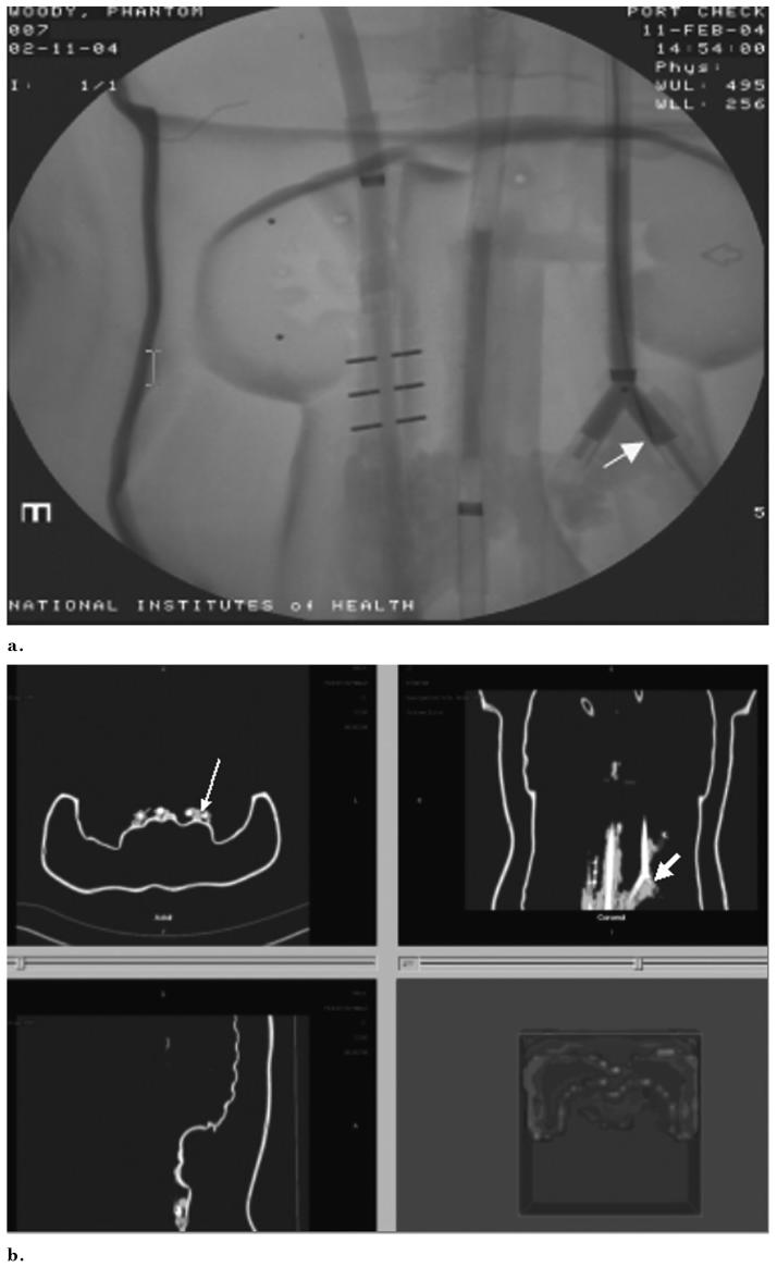
To assess the feasibility of the use of preprocedural imaging for guide wire, catheter, and needle navigation with electromagnetic tracking in phantom and animal models.
MATERIALS AND METHODS
An image-guided intervention software system was developed based on open-source software components. Catheters, needles, and guide wires were constructed with small position and orientation sensors in the tips. A tetrahedral-shaped weak electromagnetic field generator was placed in proximity to an abdominal vascular phantom or three pigs on the angiography table. Preprocedural computed tomographic (CT) images of the phantom or pig were loaded into custom-developed tracking, registration, navigation, and rendering software. Devices were manipulated within the phantom or pig with guidance from the previously acquired CT scan and simultaneous real-time angiography. Navigation within positron emission tomography (PET) and magnetic resonance (MR) volumetric datasets was also performed. External and endovascular fiducials were used for registration in the phantom, and registration error and tracking error were estimated.
RESULTS
The CT scan position of the devices within phantoms and pigs was accurately determined during angiography and biopsy procedures, with manageable error for some applications. Preprocedural CT depicted the anatomy in the region of the devices with real-time position updating and minimal registration error and tracking error (<5 mm). PET can also be used with this system to guide percutaneous biopsies to the most metabolically active region of a tumor.
CONCLUSIONS
Previously acquired CT, MR, or PET data can be accurately codisplayed during procedures with reconstructed imaging based on the position and orientation of catheters, guide wires, or needles. Multimodality interventions are feasible by allowing the real-time updated display of previously acquired functional or morphologic imaging during angiography, biopsy, and ablation.
DEVICE navigation in angiography and interventional radiology has traditionally relied on real-time imaging to monitor anatomic position during procedures. This is usually accomplished with fluoroscopy, ultrasound (US), or computed tomography (CT), but does not make optimal use of spatial or physiologic data available from previously acquired imaging like magnetic resonance (MR), positron emission tomography (PET), or arterial-phase CT. The physician conventionally makes use of this information by mentally registering the anatomic information from offline modalities to the modality used for guiding the actual procedure. This process can be inexact and may be prone to human error and inaccuracies. The outcomes and efficacy of some image-guided procedures are directly related to precision and accuracy.
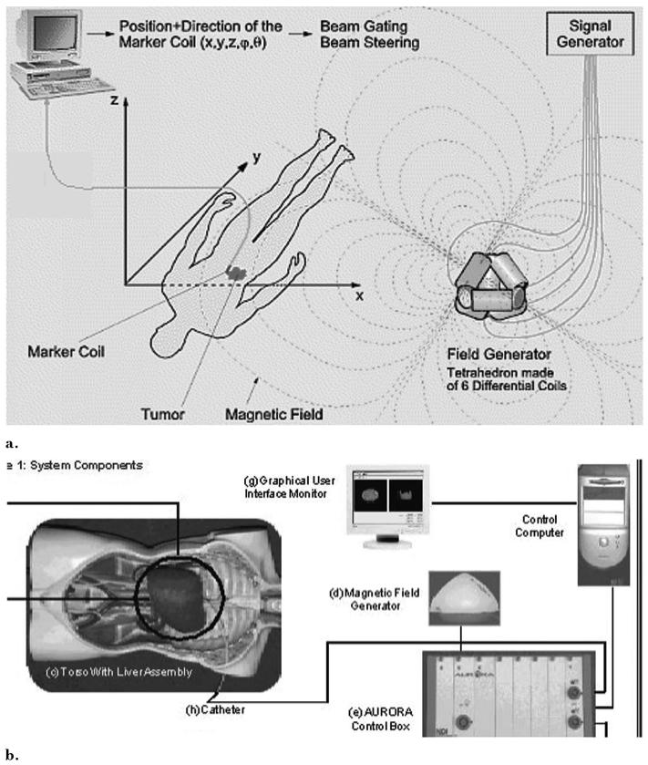
Electromagnetic tracking can provide spatial navigation information from previously acquired images (Fig 1) (1-11). This enables therapies and monitoring devices to be accurately positioned with use of the navigation system alone, without the need to continually perform imaging of the patient. In addition, preoperative plans and images can be combined with realtime imaging modalities such as fluoroscopy. Combined data can be quantitatively processed to provide the means for optimal use of the previously acquired datasets during navigated interventions. One can envision this technique being useful for many procedures that are dependent on device navigation, like biopsy, thermal ablation, angioplasty, stent-graft deployment, coiling, or regional oncologic interventions. Previously acquired morphologic imaging as well as metabolic or pharmacokinetic spatial information from PET or dynamic MR may also be brought into the procedure room with electromagnetically tracked devices. Angiography may be facilitated by realtime CT “roadmaps” that allow the physician to see nearby anatomy with the spatial resolution of CT, but without additional radiation or intravenous contrast media. Angiography without this technology is like tunnel vision; however, specific clinical scenarios in which this technology adds value remain to be validated. Preliminary data support the hypothesis that preprocedural imaging may be used to guide interventional devices during procedures with use of electromagnetic tracking.
Figure 1.
Electromagnetic tracking system components and setup: (a) electromagnetic tracking system set up and rationale. (Reproduced with permission from Northern Digital Inc [1]). (b) Components of image-guided system incorporating electromagnetic tracking for abdominal interventions.
MATERIALS AND METHODS
Tracking/Navigation Steps
Electromagnetic tracking requires several steps to allow the use of preprocedural images during procedures. Step 1 is preprocedural image acquisition with (skin or anatomic) fiducial markers in place. Step 2 is the registration of the imaging space with electromagnetic space, which requires choosing the markers on the patient with a wand (or needle guide wire or catheter) and simultaneously selecting those markers on the preprocedural image. Step 3 is real-time tracking of the device within electromagnetic space and displaying its position within the preprocedural imaging dataset during manipulation. Step 4 involves a verification image to check the actual position of the device within the patient or phantom so it may be compared with the tracked image displayed by the software.
Electromagnetic Tracking System
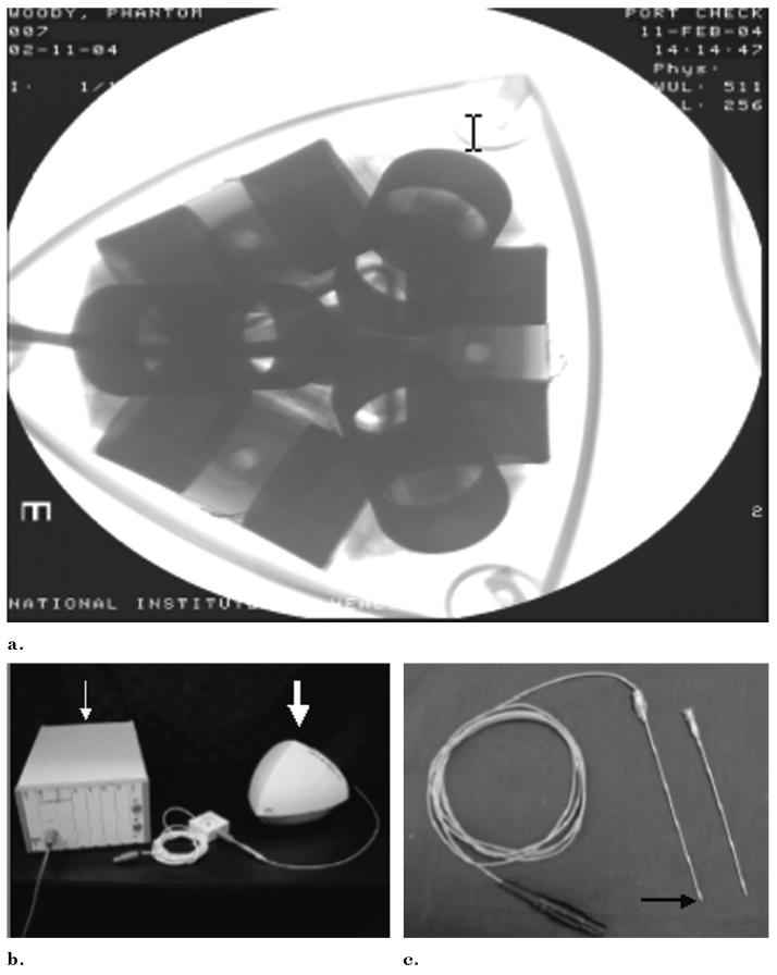
A tetrahedral-shaped electromagnetic field generator (Aurora; Northern Digital, Waterloo, ON, Canada; Fig 2) was placed in proximity to a phantom or a pig on an acrylic stand or modified passive arm (Fig 3). This generates an ultra-low electromagnetic field that enables simultaneous tracking of the position and orientation of multiple sensor coils in a volume adjacent to the field generator (1). A very weak current is induced in the sensor coil within the interventional device, and this current strength is dependent on location. The working volume is approximately 500 mm × 500 mm × 500 mm. Various tracked devices were manipulated within the phantom or pig with qualitative guidance from the previously acquired CT image and simultaneous real-time angiography. Images synthesized by the display software during sequential steps were recorded with bitmap screen saves. Simultaneous angiography spot radiographs were obtained as well as 5-megapixel digital photographs of the phantom for analysis of device position error. Angiography images were obtained in two orthogonal planes.
Figure 2.
(a) Radiograph of the field generator shows 6 differential coils for tetrahedral shaped magnetic field generation. (b) Control box (arrow), magnetic field generator (arrow), and (c) tracked device (here a needle) (black arrow) comprise the main electromagnetic tracking hardware.
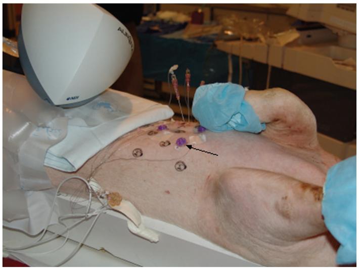
Figure 3.
Pig with external adhesive conical fiducials (arrow) for registering the previously acquired CT scan to the pig and to magnetic space.
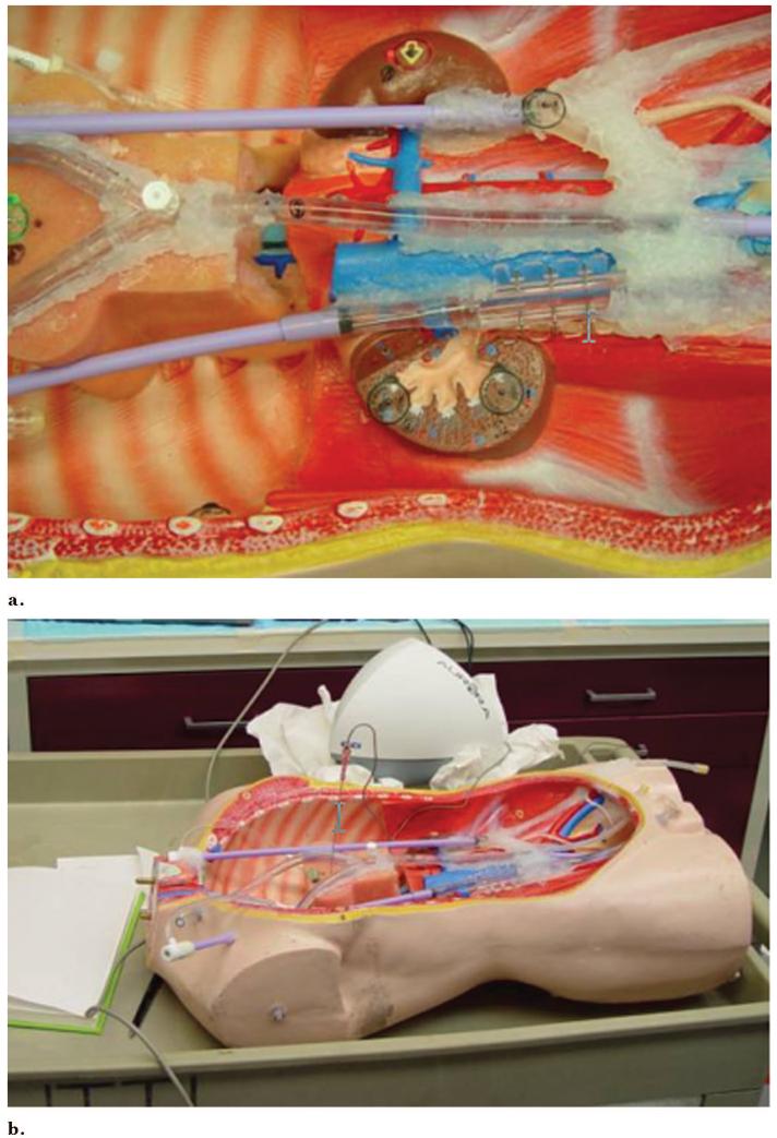
Before navigation with use of the custom-developed software, the selected CT scans were loaded, and the phantom or pig was registered to the images by clicking on the fiducial (or anatomy) on the CT image while simultaneously placing the needle, catheter, or guide wire sensor on the actual selected fiducial (or anatomy) in the phantom or pig (Figs 3, 4).
Figure 4.
Chest abdomen pelvis vascular phantom can be catheterized and has internal fiducials for registration. (a) Vascular sheaths and perfusion tubing simulate vessels. (b) The magnetic field generator is just behind the phantom in close proximity.
Hardware
Catheters, needles, and guide wires were constructed with small position and orientation sensors inside the tips (Fig 5). Five-F catheters, 18-gauge titanium needles, and 0.035- and 0.049-inch guide wires (approximately 18 gauge) were manufactured with small position-sensing coils embedded in the tips (Traxtal Technologies, Bellaire, TX). Coils measuring 0.9 mm in diameter by 9 mm in length were used for initial guide wire prototype testing, with coils 0.45 mm (0.018 inches) by 6 mm under development on an 0.035-inch guide wire (Fig 5). Small wires extended back from the guide wire and needle hub to the computer.
Figure 5.
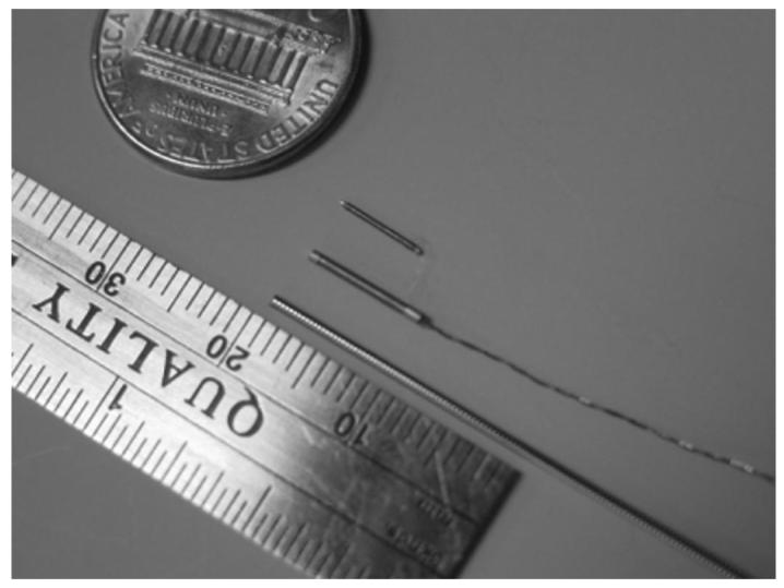
Latest sensor coil is small enough to fit on the tip of clinical guide wires (0.035-inch and 0.018-inch).
A chest, abdomen, and pelvis phantom was constructed from an open thoracoabdominal torso frame made from wood, plastic, and foam, with dialysis tubing and vascular sheaths secured with silicone sealant adhesive (Fig 3). The tubing was glued with silicone sealant to 18-F vascular sheaths (Cook, Bloomington, IN) glued to perfusion tubing (Medtronic Vascular, Santa Rosa, CA), which had three-way stopcocks and valves toward the femoral and neck regions, with silicone plugs and nondependent air valves on the opposite dead-end side to facilitate filling the tubes with iodinated contrast medium. Adhesive 1.5-mm metallic marker BB balls, doughnuts/tires, and conical multimodality markers (Beekley, Bristol, CT) were attached to the external vessel surfaces, foam pad, kidney surface, retroperitoneum, and internal chest wall. One dialysis tube had three metallic 1.5-mm-diameter rods immediately adjacent to the simulated vessel.
Six microcuries of fluorine 18 was injected with a 25-gauge needle into six conical multimodality fiducials attached to the surface of a multimodality interventional phantom (model 57; Computerized Imaging Reference Systems, Norfolk, VA) and sealed with medical-grade silicone sealant. Eighteen microcuries of 18F was injected into a plastic reservoir on a plastic rod, which was then embedded internally in the phantom. MR imaging of the phantom was also obtained with external conical fiducials.
Software
An image-guided procedures software platform called IGBiopsy was developed based on open-source software packages including the Image-Guided Surgical Toolkit (www.igstk.org) under development at Georgetown University. The software platform incorporates the Fast Light Toolkit (www.fltk.org) for the user interface, the Visualization Toolkit (www.vtk.org) for display and rendering, and the Insight segmentation and registration toolkit (www.itk.org) for image registration. The Insight segmentation and registration toolkit was recently developed by the National Library of Medicine at the National Institutes of Health and is now supported by Kitware (Clifton Park, NY).
Major software components were the Digital Imaging and Communications in Medicine (DICOM) reader component, image slice viewer, volumetric viewer, tracking module, and registration module. DICOM images were loaded onto a laptop personal computer by network transfer directly from the CT scanner.
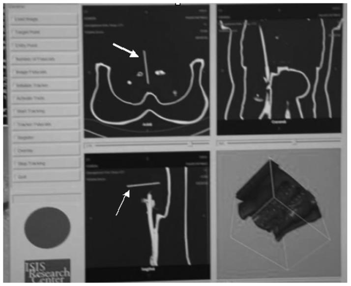
When registered, the graphical user interface of the software had triplanar reconstructed views (sagittal, coronal, axial) and a volumetric three-dimensional shaded surface display for display next to the conventional angiography image (Fig 6). The coil sensor in the guide wire tip gives position and orientation to reformat and display the corresponding CT display planes. The device location within the registered image is updated in real time during device motion. This occurs at 35 frames per second for the static two-dimensional and three-dimensional image viewer, but is slowed down to 15 frames per second with real-time display update. The rate depends on the input dataset size and hardware. For testing, the input data set was 512 bits × 512 bits × 204 bits × 16 bits and the hardware was as follows: 2.66 MHz, 1 GB RAM, 128 M ATI 9700 video card. The volumetric rendering can be significantly sped up with decimated surface rendering or use of a graphics board (Volume Pro 1000; TeraRecon, San Mateo, CA). We used the triangle decimation algorithm in rendering surface models. We also use an edge collapse algorithm to reduce the number of generated isosurface triangles to 30,000, which is a reasonable number for popular video cards to perform real-time rendering. The Volume Pro 1000 graphics board was used for real-time ray casting rendering.
Figure 6.
Graphical user interface of custom tracking software shows triplanar and volumetric displays that update in real time without radiation. The long cursor is the tracked needle (arrow).
Image datasets were transferred in DICOM format directly to a PC or a picture archiving and communication systems workstation and then transferred to a PC running Windows XP (Microsoft, Redmond, WA) through DICOM server/client. The phantom and pig CT datasets were loaded into the tracking, registration, and display software before navigation.
Phantom Experimental Protocol
Multidetector CT scans were acquired of the abdominal vascular phantom with CT scanners from multiple vendors (Mx8000IDT; Philips Medical Systems, Best, Netherlands; LightSpeed Ultra; General Electric Medical Systems, Milwaukee, WI; Somatom Volume Zoom; Siemens Medical Solutions USA, Malvern, PA) with variable slice thickness and pitch (slice thicknesses from 0.8 to 5 mm). For the phantom, two methods of registration were tested with use of external and endovascular fiducials. Four external adhesive metallic marker BB fiducials and conical fiducials (Beekley) were used for external registration. A separate phantom registration was performed with use of three internal “endovascular fiducials” like tubing, vessel bifurcations, valves, tube nipple, or embedded metallic rods (simulating adjacent internal anatomy or calcified vascular plaques). Endovascular fiducials were identifiable on fluoroscopy as well as CT and were therefore capable of multimodality registration by placing a guide wire at the fiducial location and clicking on the CT image location with navigation software. For the phantom guide wire study, registration was performed three times with four external fiducials and four times with three endovascular fiducials, with CT verification of actual location.
After registration, the error was reported as a root mean square of the difference between the selected fiducials and the calculated position of these points based on their image space positions and the calculated registration matrix. This value is calculated automatically by the software. A low root mean square is a necessary but not sufficient condition for ensuring low overall clinical error. However, this root mean square measure of error is not an accurate reflection of overall system accuracy because it may hide underlying error distribution (2). A more practical and relevant method of error measurement (“tracked to imaged” error) is to compare actual device (guide wire tip) location with displayed virtual location (registered and tracked electromagnetic position). This error measure was only done in the phantom.
Actual positions were obtained by repeating the CT scan after guide wire placement. Error distance was estimated by transferring location from tracked CT to the repeat CT. A cursor was placed on the repeat CT scan by a radiologist estimating the tracked position on the guiding software display. The distance between actual and tracked locations was calculated directly on the CT software or with Euclidian geometry if out of plane. CT scan slice thickness was 0.8 mm with no overlap for the external fiducial test and 50% overlap and 0.4 mm spacing for the endovascular fiducial test. The tracking software also calculates and displays the distance between any selected cursor’s Cartesian coordinates and those of the tracked device according to the Euclidian formula of the square root of the sum of the squares of the product of the x, y, and z coordinate differences in image space and corresponding axis spacing: [(x1 - x2)2 *spacingX2 + (y1 - y2)2 *spacingY2 + (z1 - z2)2 *spacingZ2](1/2). For the pig study, orthogonal radiographs were obtained for estimation of actual location of guide wires, and errors were subjectively estimated with simultaneous tracking screen saves.
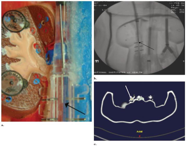
Registering the patient to the earlier imaging requires fiducials. For the phantom study, external skin fiducials and internal endovascular fiducials were tested. Endovascular fiducials were simulated by choosing angiographically visible locations within simulated vessels with identifying features that were also visible on the CT, such as vessel bifurcations or vessel location adjacent to metallic rods (Fig 7). Additionally, the actual versus displayed locations were compared for each registration method to measure practical error. Surface fiducials included conical and metallic BB markers (prototypes; Beekley).
Figure 7.
Simultaneous phantom, angiography, and tracking software demonstrate congruity of actual guide wire position with tracked position. (a) Photograph shows guide wire position (arrow). (b) Radiograph shows guide wire position (arrow). (c) Tracking shows the same guide wire position (arrow).
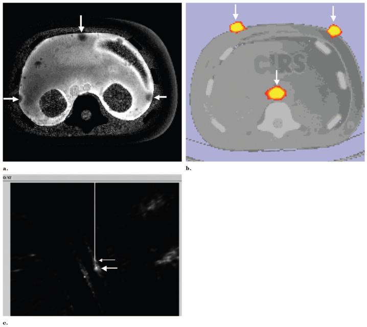
In addition to the vascular phantom, a anthropomorphic multimodality injectable interventional phantom (Model 57; CIRS, Norfolk, VA) was also used for a qualitative phantom feasibility study arm. A PET CT data set was acquired (Discovery; GE Medical Systems; Fig 8b), and the PET scan DICOM images were used to navigate a tracked needle to the internal target (Fig 8c). DICOM images were transferred to navigation software and a tracked 22-gauge needle (with a sensor coil embedded in the tip) was placed toward the internal target with electromagnetic tracking guidance. CT scan verification was performed. A similar needle navigation design was used for MR imaging images (Fig 8a) with use of a CIRS phantom and identical methods.
Figure 8.
Use of preprocedural PET and MR for needle navigation in a phantom. (a) T2-weighted MR image of phantom with gadolinium fiducials (arrows). (b) CT/PET image of interventional phantom with 6 mCi of 18F fiducials (arrows) could also be used for needle navigation. (c) Tracked needle position (small arrow) is displayed near internal target (large arrow) from preprocedural PET during tracked needle insertion.
Pig Experimental Protocol
For the pig study, all surgical maneuvers were performed with standard sterile surgical techniques under a nonsurvival animal study approved by the senior author’s institutional animal care and use committee, in compliance with the National Institutes of Health Guide for the Care and Use of Laboratory Animals and applicable federal regulations and standards. The pig vessels were accessed via US-guided single-wall modified Seldinger technique with a 21-gauge needle and an 0.018-inch nitinol guide wire with sequential dilation to 7 F for eventual placement of a 9-F vascular sheath. The jugular vein was accessed in all three pigs, the carotid artery in pigs 2 and 3, and femoral artery and vein in pig 3. In addition to tracked guide wires, pig 3 also had a tracked catheter placed. US guidance was performed with an HDI 5000 US device (Philips Medical Systems). Angiography was performed on the pigs with biplane angiography (Neurostar; Siemens Medical Solutions USA).
For the pig study, only external skin fiducials were used. Before CT, six external skin doughnut fiducials (IZI Medical Products, Baltimore, MD) or conical fiducials (Beekley) were placed on the abdomen in proximity to the area of interest for registration (Fig 3). Thoracoabdominal enhanced CT scans were obtained in pigs after 2-mL/sec intravenous injection of iodinated nonionic contrast material at a rate of 1 mL/kg body weight on a fourrow detector CT (Somatom Volume Zoom; Siemens Medical Solutions USA) with 3-mm collimation, with 1-mm spacing. Registration was performed with use of six skin fiducials.
Tracked needles, guide wires, and catheters were placed in the pigs with real-time electromagnetic navigation. A 6-F guiding sheath tip or a tracked catheter was placed in proximity of the desired location, and the tracked guide wires were then inserted into the sheath while tracking position. Simultaneous tracking software screen saves and biplane angiography images were obtained at multiple locations in each pig during guide wire manipulation. Locations included the right atrium, inferior vena cava, aorta, left renal artery, and a lumbar artery. Biplane images were obtained with and without a contrast material bolus. Tracked CT image guide wire tip locations were subjectively compared with biplane angiography tip locations for accuracy, although no formal intermodality measurements were made.
Study Endpoints
Root mean square errors were recorded for all registrations in phantoms and pigs, providing an estimate of the quality of the registration itself. However, the more clinically relevant error measure compared actual images with tracked images. Actual-to-tracked guide wire tip location was also calculated for the phantom trials with external and internal fiducial methods as described earlier. Subjective accuracy of guide wire tracking in pigs was estimated comparing preprocedural CT with procedural angiography; however, this intermodality method was purely qualitative.
To test the practical ability of this technique to navigate wires to specific vessels, tracked guide wires were used to navigate down both sides of a vessel bifurcation three times with use of preprocedural CT alone for guidance, without direct vision or angiography assistance.
We also investigated the effect of the clinical setup on the equipment. It is well-known that large metallic objects can distort the accuracy of some types of electromagnetic tracking equipment. To this end, each registration method was also tested on two different clinical angiography tables (Integris; Philips Medical Systems, and Angiostar; Siemens Medical Solutions USA) and on the CT table (Mx 8000IDT; Philips Medical Systems) for multimodality navigation and display. The image intensifier was placed above the vascular torso phantom and the electromagnetic field generator was placed midway between the image intensifier and the table. The image intensifier was lowered incrementally until more than 1 mm distortion of the tracking was noted.
RESULTS
Electromagnetic tracking of interventional radiology devices was successfully performed in phantoms and pigs with qualitatively accurate display of previously acquired datasets. The position of the devices within phantoms and pigs was accurately displayed during angiography and biopsy procedures, with manageable (less than 5 mm) system accuracy.
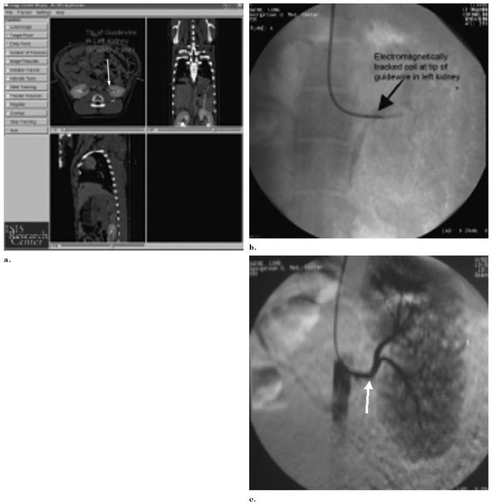
In a pig model, six superficial fiducials were used for image registration(Fig 3). Preprocedural CT scans depicted the anatomy in the region of the devices with real-time position updating. Catheters and guide wires were successfully navigated from the jugular vein, through the heart, and to the inferior vena cava; from the femoral vein to the inferior vena cava; and from the carotid artery, down the aorta, and selectively into a lumbar artery as well as the left renal artery (Fig 9). Angiography confirmed accurate selective catheterization. Error was subjectively estimated to be less than 5 mm in the aorta, renal artery, lumbar artery, and inferior vena cava despite no respiratory correction or gating. Most of this error was likely respiratory misregistration. Pig registration occurred in ventilated pigs with the ventilator suspended but with occasional spontaneous breathing. There was minimal delay (1-3 hours) between CT and experiments in pigs, and pigs were restrained on a special table, which minimized motion error.
Figure 9.
Tracked and actual position of guide wire in renal artery. (a) Triplanar view of arterial guide wire tracked within an anesthetized pig, displayed in real time on recently acquired enhanced CT scan. The cursor (arrows) shows the tracked location of the guide wire in the left renal artery. (b,c) Corresponding radiograph and digital subtraction angiography verify actual guide wire location in left renal artery (arrows).
Electromagnetic tracking of guide wires was successful, rapid, and accurate with use of three different vendors’ CT DICOM datasets on two different vendors’ angiography tables and a CT table. For the vascular phantom study, median root mean square registration error for three trials with only four external fiducials was 1.20 (range, 0.73-1.20 mm; Table 1), and the average practical tracked-to-imaged error was 2.5 mm (2.7 mm, 3.2 mm, and 1.6 mm). Four trials with only three endovascular fiducials were performed (Table 2). For these endovascular trials, the root mean square registration error median of 1.15 mm (range, 1.15-2.58 mm) with a mean tracked-to-imaged error of 1 mm (2.2 mm, 0.8 mm, 0 mm) with use of 0.8-mm collimation with 0.4-mm overlap. There was a relatively low tracked-to-imaged error even in the one trial with suboptimal registration (root mean square, 2.58).
Table 1.
Guide Wire Tracking Error and Accuracy for Skin Fiducials in Three Vascular Phantom Trials
| Trial | Root Mean Square | Transverse XY Error (mm) | Craniocaudal Z Error (mm) | Total Calculated Error: Distance Calculation (mm) |
|---|---|---|---|---|
| 1 | 0.73 | 2.20 | 1.60 | 2.7 |
| 2 | 1.20 | 3.10 | 0.80 | 3.2 |
| 3 | 1.20 | 1.60 | 0.00 | 1.6 |
| Average | 2.5 |
Table 2.
Guide Wire Tracking Error and Accuracy for Endovascular Fiducials in Four Vascular Phantom Trials
| Trial | Root Mean Square Registration Error | Axial XY Error (mm) | Craniocaudal Z Axis Error (mm) | Total Calculated Error (mm) |
|---|---|---|---|---|
| 1 | 2.58 | 1.0 | 0.8 | 1.28 |
| 2 | 1.15 | 2.2 | 0 | 2.20 |
| 3 | 1.15 | 0.8 | 0 | 0.80 |
| 4 | 1.15 | 0 | 0 | 0.00 |
| Average | 1.07 |
Placing fiducials, selecting fiducials on preoperative imaging, and registering fiducials by tapping or inserting a guide wire to the specified locations requires only a period of several minutes, and can be semiautomated in the future. Image-based registration algorithms will further facilitate this process. The actual registration/location of six device positions in electromagnetic space can take as little as 35 seconds. Guide wires were manipulated and vessels selected with use of the previously acquired CT displayed with electromagnetic tracking without angiography (Fig 10). Simultaneous angiography, phantom digital pictures, and tracking demonstrated accurate registration with near-exact congruity of guide wire position (Fig 7).
Figure 10.
Tracking technique alone used for guide wire navigation. (a) Radiograph shows guide wire tip (arrow) just past simulated vessel bifurcation. (b) Triplanar tracking views of guide wire tip (arrow) placed down the left branch of vessel bifurcation.
Metal interactions were inconsequential, given minor limitations within certain constraints. The image intensifier could be brought as close as 10 cm away from the field generator without significantly altering the tracking coordinates in the phantom. Significant was defined as greater than 1 mm shift. Closer than 10 cm, there was slight shifting of the tracking coordinates from metal interactions. Tracking while directly within the CT gantry also caused metal distortion error, but this minimized when not directly in the gantry. Turning on the x-ray tube did not affect the tracking data. Accurate registration was obtained with the field generator 20 cm above the CT and angiography tables and secured with a locking passive arm connected to the table.
Electromagnetic tracking was used as the sole guidance method to successfully navigate a tracked guide wire down a specific vessel bifurcation three times (Fig 10). PET and MR datasets were also successfully loaded and registered to the phantom for navigation within metabolic and functional datasets (Fig 8). An internal radiopharmaceutical target was located with electromagnetic tracking with a tracked needle (Fig 8). This could facilitate guiding percutaneous biopsies to the most metabolically active region of a tumor.
DISCUSSION
Electromagnetic tracking of instruments in interventional radiology can provide real-time display of position and orientation within previously acquired three-dimensional imaging datasets. This may facilitate use of preprocedural spatial or anatomic information during interventional procedures. This registration joins imaging space to magnetic space of the patient. The patient also undergoes imaging in real time with the same or a different modality. Tracking may enable accurate and precise navigation of guide wires, catheters, needles, and even radiofrequency ablation probes (work in progress). Accuracy and precision in image-guided therapy could translate into improved outcomes and patient care.
Electromagnetic tracking has recently undergone miniaturization and sophistication that enables easy use in image-guided therapies. Previous animal and phantom models have been reported for similar techniques for navigation during transjugular intrahepatic portosystemic shunt creation, vena cava filter placement, cardiac catheterization, bone screw deployment, liver biopsy, venous catheter placement, and bronchoscopy (3-6,8, 10,11); however, these systems used a much larger sensor that precluded placement into small interventional devices. With recent miniaturization, sensor coils as small as the tip of an 0.018-inch guide wire can now be manufactured, which makes tracking and navigation of clinical guide wires and micro-guide wires feasible. This enables guide wire manipulation without the use of fluoroscopy radiation or intravenous contrast medium. Accurate and precise guide wire tip navigation can be performed with real-time updating of registered imaging.
Animal and phantom validation of the feasibility of such exciting technologies is promising, but eventual clinical utility remains speculative. Respiratory motion compensation, patient motion error, and organ shift during procedures remain significant obstacles to routine clinical deployment. Operator time, software setup, registration methods, automation of system setup, ease of use, integration with angiography systems, and cost effectiveness also remain unresolved issues. This study was limited by lack of a respiratory phantom, lack of respiratory registration, lack of time data, and potential subjective inaccuracies when comparing imaged with virtual coordinates. Fiducial location selection (and lack of options for such) not in close proximity to the working area may adversely affect error.
However, overall time for registration with use of internal or external fiducial methods was reasonable and was accomplished in several minutes. The commercially available electromagnetic field generator provides a relatively small usable field of approximately 500 mm × 500 mm × 500 mm, with a “sweet spot” region of most accurate registration of approximately 500 mm × 500 mm × 200 mm. Even given these limitations, the technology is robust, inexpensive, and accurate; does not require line of sight; and offers tremendous potential for bringing offline imaging into the procedure suite. Alternate field generator configurations could improve the field of view with less electromagnetic field inhomogeneities.
Modern surgical device tracking has usually relied on electromechanical, infrared-optical, or electromagnetic technology. Stereotactic frames have been used throughout the 20th Century, predominantly in neurosurgery, to make intraoperative use of preoperative imaging. Electromagnetic tracking has the advantage of not requiring line of sight, unlike an optically tracked device. Latest-generation electromagnetic tracking is less susceptible to interference from metal objects and can work with much smaller sensors compared with earlier-generation electromagnetic systems. This enables endovascular guide wire tracking, which can be performed inside virtually any commonly used vascular catheters. Next-generation guide wire prototypes include smaller guide wires, optimized “torquablility,” tensile strength, and tip flexibility and configurations. This should facilitate automation of image-based registration and correction for breathing motion.
Multimodality tracking might prove useful in any clinical scenario in which one does not know the precise anatomic location of the catheter or its relation to adjacent anatomy. The guide wire may be useful as a CT roadmap, similar to angiographic digital subtraction angiography roadmapping, except with CT displayed during fluoroscopic updating. Although speculative, this could prove useful for stent-graft placement to see the exact location of adjacent excluded vessels and to assess risk for endograft leak, for stent deployment or angioplasty for exact location of stenosis, for saccular aneurysm coiling occlusion, or for locoregional oncologic therapies such as isolated liver perfusion, chemoembolization, or radiofrequency ablation. Tracked catheters could assist in transhepatic portosystemic shunt creation by localizing the portal vein and can help navigate complex vascular networks when there is vessel overlap. CT angiography roadmapping could decrease radiation doses in long, difficult cases like spinal arteriovenous malformations. Renal insufficiency could be managed with lower intravenous contrast material doses.
Although standard image-guided biopsy and ablation uses morphologic imaging, there may be a role for navigation with functional or metabolic imaging. Both are possible with electromagnetic tracking registration of preprocedural imaging. Use of PET or dynamic MR datasets to guide biopsy locations may facilitate the temporospatial analysis of cancer therapies. Sequential biopsies may be performed to analyze the genomics and proteomics of tumor growth and response to therapy. The use of PET data for navigation may be a useful research tool. In the future, it may be important to sample the most metabolically active region of a tumor, as defined by PET, to decide what patient needs what therapy at which time. Specific tumors may be responsive to specific patient specific and tumor-specific chemotherapy cocktails. The use of PET data for interventions (ie, PET roadmapping) does not require the continuous use of a PET scanner suite for the intervention.
Electromagnetically tracked needles and radiofrequency ablation probes could also provide accurate mapping of thermal ablation regions within a preprocedural image dataset. This could be a tool to facilitate implementation of a complex treatment plan involving complex geometries to ensure treatment zone overlap without gaps, which is prerequisite for successful thermal ablation. A tumor that was visible on only a certain MR sequence or on only arterial-phase imaging could be targeted for biopsy or ablation by registration of that imaging sequence with an electromagnetically tracked needle or probe. This enables the use of this offline imaging for complex interventions without the additional step of mental coregistration, which may be prone to human error. Additionally, sensor coils are now small enough that one coil could be used for breathing motion gating and several others for tracking the treatment device or biopsy needle.
Metal interaction caused interference and shifted the tracking coordinates during angiography when the image intensifier was less than 10 cm from the electromagnetic field generator. Previous studies have included some preliminary investigations into the circumstances and quantified the magnitudes at which this occurs (7). Fluoroscopy itself did not substantially alter the electromagnetic fields during the experiments. In fact, no significant interference with the electromagnetic field was seen at relevant imaging distances (>10 cm) on either vendor’s table.
The tracking system was accurate and flexible enough to facilitate selective navigation with use of endovascular and external fiducial markers and in animal and phantom models. The use of endovascular structures for semiautomated data registration may provide a corrective solution for error from respiratory misregistration, organ shift, cardiac motion, or patient motion. It is encouraging that the pigs were accurately registered with external fiducials alone, implying that a rough registration may be all that is needed for basic interventions and navigation. In vivo, calcified plaques, vessel bifurcations, vessel origins, and diaphragm silhouette or organ contour levels can be seen on real-time fluoroscopy and on previously acquired CT scans, and could provide internal fiducials for more accurate registration of electromagnetic field to CT (and imaging to patient). In this manner, one could use previously acquired CT scans in angiography without prior planning or complex fiducial placement. This is accomplished by clicking on the CT anatomy with a cursor while simultaneously placing the guide wire near known anatomic structures (eg, calcium, diaphragm) with angiographic guidance. Alternatively, one could match the CT and electromagnetic field data sets together with use of orthogonal biplane angiography or rotational angiography that was then reduced to axial images. It is also encouraging that less than 5 mm error was possible even with only three or four fiducials in the phantom, and with six external fiducials in a breathing animal.
Use of electromagnetically tracked devices within previously acquired imaging could decrease radiation dose significantly by allowing CT roadmapping, CT angiography roadmapping, or MR angiography roadmapping to guide conventional angiographic interventions. This is similar to digital subtraction angiography roadmapping, except it makes use of the wealth of exquisite diagnostic images that have been underused for angiographic and image-guided interventions.
Previously acquired CT, MR, or PET data can be accurately codisplayed in angiography and interventions with reconstructed imaging based on the position and orientation of catheters, guide wires, or needles. This system may decrease radiation dosage and enables multimodality roadmapping for interventions by allowing the real-time use of previously acquired functional or morphologic imaging during angiography, vascular interventions, biopsy, and ablation.
Acknowledgments
This work was funded by U.S. Army grant DAMD17-99-1-9022. The content of this manuscript does not necessarily reflect the position or policy of the U.S. Government. Thanks are also due to the animal care staff at Georgetown University including veterinary technician Heidi Derr and director Lisa Portnoy, DVM. Thanks to David Sun for assistance building the vascular phantom.
Abbreviations
- DICOM
Digital Imaging and Communications in Medicine
- PET
positron emission tomography
Footnotes
B.J.W. and K.C. are coinventors on related US Patent Application #10/377,528, “Interstitial Magnetic Position Sensor System and Needle for Surgical and Image-guided Therapy Navigation.” B.J.W. and N.G. are coinventors on US Patent Application: “Design for Guiding and Electromagnetic Tracking of Radiofrequency Ablation Needle” (US Provisional Patent Application # 60/625,186). Philips owns intellectual property and has market interest in this area. J.K., J.B., and S.K. are salaried employees of Philips Electronics. The mention of commercial devices or products, their source, or their use in connection with material reported herein is not to be construed as either an actual or implied endorsement of such products by the National Institutes of Health, the Department of Health and Human Services, or the Public Health Service. N.G. is President and a major shareholder of Traxtal, Inc.
References
- 1.Seiler PG, Blattman H, Kirsch RK, Muench RK, Schilling C. A novel tracking technique for the continuous precise measurement of tumour positions in conformal radiotherapy. Phys Med Biol. 2000;45:N103–N110. doi: 10.1088/0031-9155/45/9/402. [DOI] [PubMed] [Google Scholar]
- 2.Frantz DD, Wiles AD, Leis SE, Kirsch SR. Accuracy assessment protocols for electromagnetic tracking systems. Phys Med Biol. 2003;48:2241–2251. doi: 10.1088/0031-9155/48/14/314. [DOI] [PubMed] [Google Scholar]
- 3.Solomon SB, White P, Wiener CM, Orens JB, Wang KP. Three-dimensional CT-guided bronchoscopy with a real-time electromagnetic position sensor. Chest. 2000;118:1783–1787. doi: 10.1378/chest.118.6.1783. [DOI] [PubMed] [Google Scholar]
- 4.Solomon SB, Dickfield T, Calkins H. Real-time cardiac catheter navigation on three-dimensional CT images. J Intervent Cardiac Electrophysiol. 2003;8:27–36. doi: 10.1023/a:1022379612437. [DOI] [PubMed] [Google Scholar]
- 5.Solomon SB, Magee CA, Acker DE, Venbrux AC. Experimental nonfluoroscopic placement of inferior vena cava filters: Use of an electromagnetic navigation system with previous CT data. J Vasc Intervent Radiol. 1999;10:92–95. doi: 10.1016/s1051-0443(99)70017-5. [DOI] [PubMed] [Google Scholar]
- 6.Solomon SB, Magee C, Acker DE, Venbrux AC. TIPS placement in swine, guided by electromagnetic real-time needle tip localization displayed on previously acquired 3-D CT. Cardiovasc Intervent Radiol. 1999;22:411–414. doi: 10.1007/s002709900416. [DOI] [PubMed] [Google Scholar]
- 7.Glossop ND, Cleary K, Banovac F. Needle tracking using the Aurora magnetic position sensor; Presented at: The Second Annual Meeting of Computer Aided Orthopedic Surgery; June 19-22, 2002; N.M.: Santa Fe; [Google Scholar]
- 8.Banovac F, Glossop N, Lindisch D, Tanaka D, Levy E, Cleary K. Liver Tumor Biopsy in a Respiring Phantom with the Assistance of a Novel Electromagnetic Navigation Device; Proceedings (Part I) of the Medical Image Computing and Computer-Assisted Intervention (MICCAI 2002) 5th International Conference; Tokyo, Japan. September 25-28, 2002.pp. 200–207. [Google Scholar]
- 9.Wood B, Lindisch D, Ranjan S, Glossop N, Cleary K. Electromagnetically tracked guidewires for interventional procedures; Program and Abstracts from Computer Aided Radiology and Surgery (CARS 2004); Chicago, Ill. June 14, 2004.p. 1309. [Google Scholar]
- 10.Glossop N, Cleary K, Burgess J, Corral G. Magnetically tracked bone screws for image guided intervention; Program and Abstracts from Computer Aided Radiology and Surgery (CARS 2004); Chicago, Ill. June 14, 2004.pp. 602–607. [Google Scholar]
- 11.Sacolick L, Patel N, Tang J, Levy E, Cleary K. Electromagnetically tracked placement of a peripherally inserted central catheter. Proc SPIE. 2004;5367:724–728. [Google Scholar]


