Abstract
In the dynamic clamp technique, a typically nonlinear feedback system delivers electrical current to an excitable cell that represents the actions of “virtual” ion channels (e.g., channels that are gated by local membrane potential or by electrical activity in neighboring biological or virtual neurons). Since the conception of this technique, there have been a number of different implementations of dynamic clamp systems, each with differing levels of flexibility and performance. Embedded hardware-based systems typically offer feedback that is very fast and precisely timed, but these systems are often expensive and sometimes inflexible. PC-based systems, on the other hand, allow the user to write software that defines an arbitrarily complex feedback system, but real-time performance in PC-based systems can be deteriorated by imperfect real-time performance. Here we systematically evaluate the performance requirements for artificial dynamic clamp knock-in of transient sodium and delayed rectifier potassium conductances. Specifically we examine the effects of controller time step duration, differential equation integration method, jitter (variability in time step), and latency (the time lag from reading inputs to updating outputs). Each of these control system flaws is artificially introduced in both simulated and real dynamic clamp experiments. We demonstrate that each of these errors affect dynamic clamp accuracy in a way that depends on the time constants and stiffness of the differential equations being solved. In simulations, time steps above 0.2 ms lead to catastrophic alteration of spike shape, but the frequency-vs.-current relationship is much more robust. Latency (the part of the time step that occurs between measuring membrane potential and injecting re-calculated membrane current) is a crucial factor as well. Experimental data are substantially more sensitive to inaccuracies than simulated data.
Introduction
The dynamic clamp technique was first developed and used in cardiac electrophysiology. Early systems implemented linear gap junction conductances via analog circuitry (Scott, 1979; Tan and Joyner, 1990). In the early 1990’s, neurophysiologists developed more elaborate versions of the technique with the power to represent ligand-gated conductances (Robinson and Kawai, 1993; Sharp et al., 1993) and voltage-gated conductances (Sharp et al., 1993). By inserting simulated conductances into a cell membrane, the experimenter gains fine, selective control over system parameters that cannot be perfectly modulated pharmacologically. Since its conception, a variety of dynamic clamp systems have been developed and used (reviewed by Prinz et al., 2004). Existing systems use analog circuitry (e.g., Tateno and Robinson, 2006), dedicated programmable hardware with a real-time operating system (e.g., Kullmann et al., 2004), or software running on a standard PC (Butera et al., 2001; Dorval et al., 2001; Pinto et al., 2001). Relative to other solutions, PC-based software has advantages in cost and/or flexibility. However, in software-based applications it is more challenging to ensure “hard” real-time performance (i.e., real-time performance that is never late). Hard real-time performance can be ensured using real-time extensions of the Linux operating system (Butera et al., 2001; Dorval et al., 2001; Raikov et al., 2004), but with reduced ease-of-installation and ease-of-use for a substantial fraction of the community. The consequences of violations of hard real-time performance in dynamic clamp applications have not been assessed in detail. Here, we attempt to provide this missing analysis.
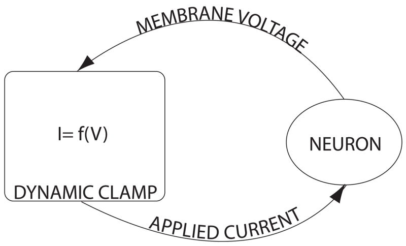
A dynamic clamp system acts very much like a digital filter; it periodically samples inputs and computes outputs (Fig. 1). The “speed” of a platform usually refers to three attributes: time step, jitter, and latency. These components of a system’s speed can be characterized as follows. The target period of the system is called the time step. Ideally this value would be infinitesimal so that we would be able to acquire and output all possible frequencies; however, in practice our time steps are far from this ideal. This is because a lower bound is set by the amount of processing time needed to complete a single input-output calculation. In practice, the actual time step that we observe is a random variable with a mean centered about the target time step. This variation is called jitter, and is a direct result of the non-deterministic nature of modern computer architectures (e.g. cache misses, bus contention, and super-scalar execution). Typically solutions based on general purpose operating systems will always suffer from high levels of jitter because the underlying system is designed to distribute clock cycles fairly among many competing processes. Latency, the time between receiving an input and updating the corresponding physical output channel roughly determines the lower bound on time step. Latency exists because it takes a finite amount of time to perform analog to digital conversion, do some computation, and convert back from digital to analog.
Figure 1. Dynamic clamp feedback loop.
This schematic representation of a dynamic clamp system illustrates the feedback controller which measures membrane voltage, calculates a current to apply based on the dynamics of the simulated conductance, and feeds that current back to the cell. Typically the membrane voltage and applied current are conducted through the same electrode.
The goal of this work is to analyze the performance implications of imperfect control on a particularly resource sensitive dynamic clamp experimental protocol: virtualizing a voltage-dependent current source with sub-millisecond activation time constants. Here, we present examples of the errors introduced by both these timing imperfections and by the use of various differential equation solvers. We predict the performance benchmarks dynamic clamp systems will require using computational simulations of dynamic clamp experiments and test these predictions in an actual dynamic clamp experiment.
Methods
Computational Simulations
To predict the effects of dynamic clamp performance flaws, a simulated dynamic clamp experiment was conducted using a point model of a hippocampal CA1 pyramidal neuron (soma extracted from Migliore et al., 1999, including nonlinearities to preserve specified minimum values for each of the time constants). All simulations were done in MATLAB (The Mathworks, Natick, MA). The model contains a single Na+ channel, and two K+ channels (A-type and Delayed Rectifier). As a control, this model was run using the built-in MATLAB solver ode15s, a stiff solver with a variable time step. To simulate a “virtualized” channel, the current for the channel was injected using a fixed time step (25, 50,100, 200, or 250 μs) with one of three solvers (forward Euler, 4th order Runge-Kutta, or the MATLAB stiff ODE solver (using default settings for tolerance, maximum step size, etc.), which relies on numerical differentiation formulas; see Shampine and Reichelt, 1997). Jitter was introduced by simulating the channel with a uniformly distributed random time step between 25μs and a predetermined upper bound. Latency was modulated by adding a fixed delay between reading the input voltage and updating the current contributed by the channel to the optimally modeled CA1 pyramidal neuron.
Brain Slice Techniques
All protocols were approved by the Boston University Animal Care and Use Committee. Transverse hippocampal brain slices (400 μm) were prepared as previously described (Netoff et al., 2005) from Long-Evans rats aged P14–32. After a 1hr incubation period, they were transferred to the recording chamber. Whole cell patch clamp access was acquired using a 3–6MΩ electrode filled with (in mM)120 potassium gluconate, 10 KCl, 10 Hepes, 4 Mg-ATP, 0.3 Tris_GTP, 10 sodium phosphocreatine, and 20 units/ml creatine kinase. All electrophysiological recordings were obtained at 33°C with a Multiclamp 700A (Axon Instruments, Foster City, CA).
Dynamic Clamping
Real-time feedback for dynamic clamp experiments was implemented using custom written software for RTAI, a real-time kernel modification for Linux. The application ran in real-time and sat in a tight loop while never sleeping; thus, the computer was effectively frozen while the experiment was taking place. The system was capable of simulating channels with a time step duration of 12μs. The actual duration of each time step was recorded to ensure that time step duration, jitter, and output latency were tightly controlled.
Data Analysis
To analyze the effect of errors introduced on action potential shape, the integral of the square difference from control over a single spike was calculated. That is to say the control, which amounts to a voltage trace of the model neuron without any of the channels virtualized, was first computed. Next, the model was run for 10ms with either the Na+ or K+ channels virtualized, using some value of time step, jitter, and latency. The responses were aligned at some threshold crossing, a point by point difference from control was computed, each difference was squared, and the Riemann sum was taken over time. Error is reported in units of V2. We include raw traces to give the reader an indication of how a given amount of error corresponds to the visual appearance of the action potential.
The effect of imperfect dynamic clamp on firing rate was evaluated by computing the frequency-current relationship for both the control and experimental cases. For a range of values, current was applied to the cell for one second. The number of spikes generated within that time window was counted to determine average firing rate.
Results
Differential Equation Solver
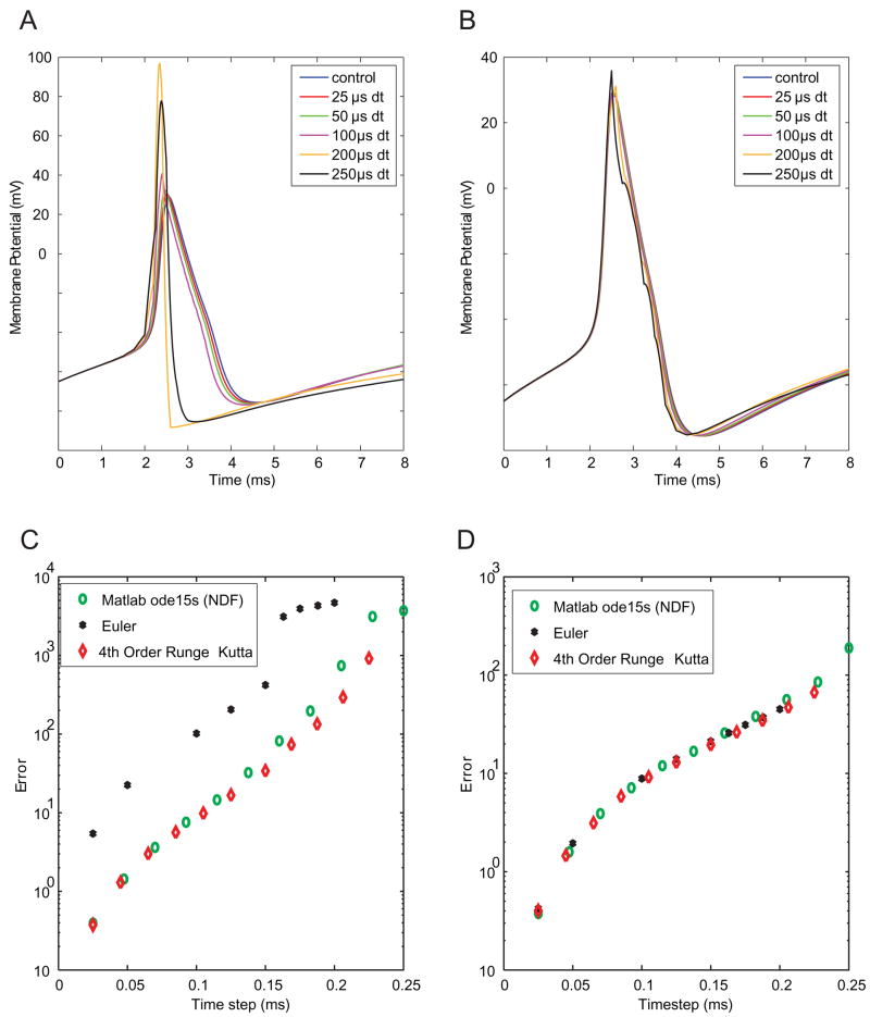
To confirm the accuracy and stability of the numerical methods, namely choice of a solver, voltage-gated Na+ channels were virtualized with each of three different solvers. Virtualizing Na+ channels using the Euler solver led to drastic error (Figs. 2A, 2C). In contrast, both the NDF solver (Shampine and Reichelt, 1997) and the 4th Order Runge-Kutta method provided accurate solutions. Our results with the Runge-Kutta solver suggest that there were no noticeable deleterious effects of the non-smooth right-hand sides in the Migliore model. The solver method was less critical for virtualizing K+ channels (Figs 2B, D). In subsequent simulations, we use the NDF solver with a variable time step for simulating ideal channels and the 4th order Runge-Kutta with a fixed time step to simulate virtualizing channels and for the brain slice experiments.
Figure 2. Accuracy of dynamic clamp simulations with different numerical solvers.
A: Traces of simulated evoked action potentials. In this case, Na+ channels were simulated using the Euler method at the time step indicated in the legend. K+ channels and integration of the membrane equation were performed in high-precision using the NDF solver (see Methods). B: Traces of simulated action potentials in which K+ channels were virtualized at a given time step using the Euler method, with other elements integrated with high precision. C: Plots of error vs. time step for three methods of Na+ channel virtualization. Error (units of V2) is much larger for the Euler method than for the NDF or Runge-Kutta methods. D: Error vs. time step for virtualization of K+ channels. Accuracy is relatively independent of the solver method.
Time step duration
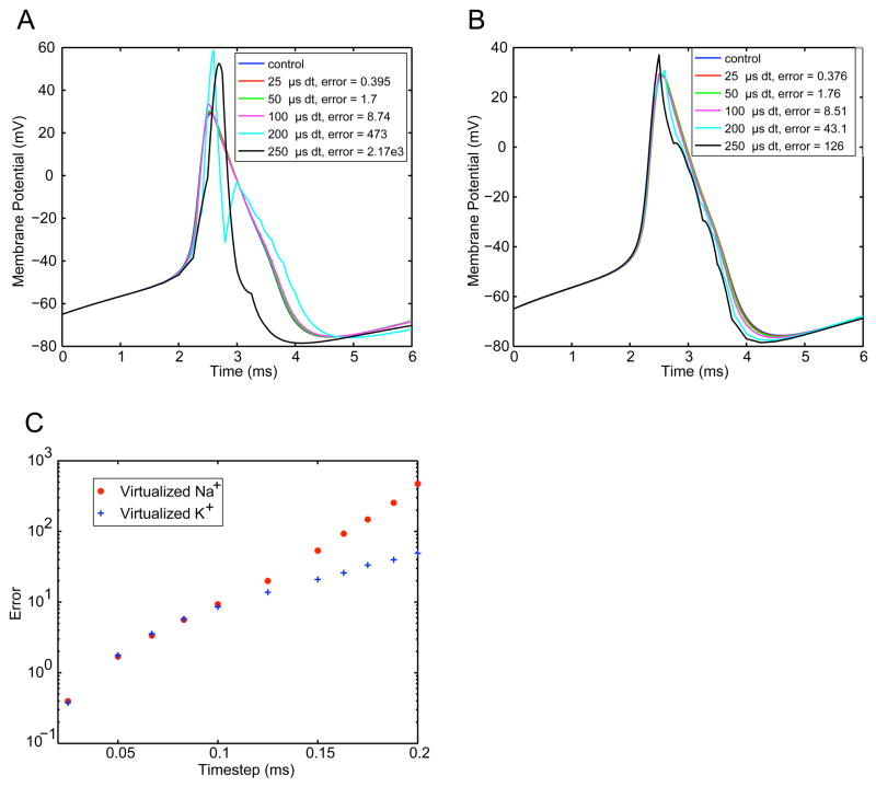
To evaluate the effects of fixed time step duration on artificially introduced ionic conductances, Na+ and K+ channels were independently knocked-in using various fixed time steps in simulated dynamic clamp experiments. In each case, the implementation of other set of voltage-gated channels was updated at a very fast time scale to ensure accuracy. Time step had a substantial effect on the shape of the model’s spikes (Fig. 3). For Na+ virtualization (Fig. 3A), prolonged time steps resulted in channels that stayed open for too long, giving a much larger peak of the action potential. For the time steps immediately following the peak, the overshoot causes very large outward currents to be calculated. Thus the resulting action potential was both larger in amplitude and shorter in duration than the control. K+ channel virtualization (Fig. 3B) at low rates resulted in a larger afterhyperpolarizing current, which caused an artificially large negative deflection following an action potential. Errors were quantified by calculating the squared difference from control spikes (Fig. 3C). Virtualizing Na+ with a time step greater than 50μs introduced significant spike distortion, whereas virtualizing K+ a time step as large as 100μs did not introduce significant distortion.
Figure 3. Effects of time step on dynamic clamp accuracy.
In separate simulations Na+ (A) and K+ (B) channels were virtualized at a given time step using the 4th-order Runge-Kutta solver. Generally, large time steps lead to massive distortions when Na+ channels are virtualized (A); virtualization of K+ channels leads to more subtle distortions, mainly by increasing the spike afterhyperpolarization. C: Summary data showing error (V2) vs. time step for the two cases.
Jitter
We next studied the effects of jitter, or variation in time step, on dynamic clamp performance. For these simulated dynamic clamp experiments, the time step for the virtual ion channels was a uniformly distributed random variable between 25μs and the specified worst-case. Figure 4 shows error as a function of worst case time step. Both the shape of the action potential (Fig. 4A–B) and the quantification of error (Fig. 4C–D) reveal performance better than that observed for the fixed worst-case time step shown in Fig. 3 and in blue symbols in Fig. 4C. These data imply that the error for a randomly distributed time step has an upper bound defined by the error of the fixed worst case time step. In other words, the maximal error for a random time step with worst-case of 50μs is equal to the error for a fixed time step of 50μs. This property suggests that jitter can be ignored as long as the worst case time step produces satisfactory accuracy.
Figure 4. Effects of time-step jitter on dynamic clamp accuracy.
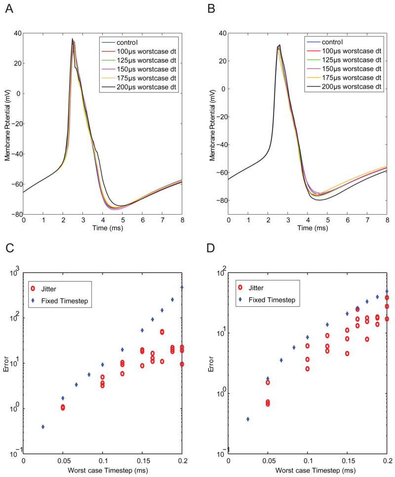
In these simulations, Na+ (A, C) and K+ (B, D) channels were virtualized at a time step that varied randomly from 25μs to a given worst-case value. As shown in individual traces (A–B) and summary data (C–D), error is bounded above by the worst-case time step.
Latency
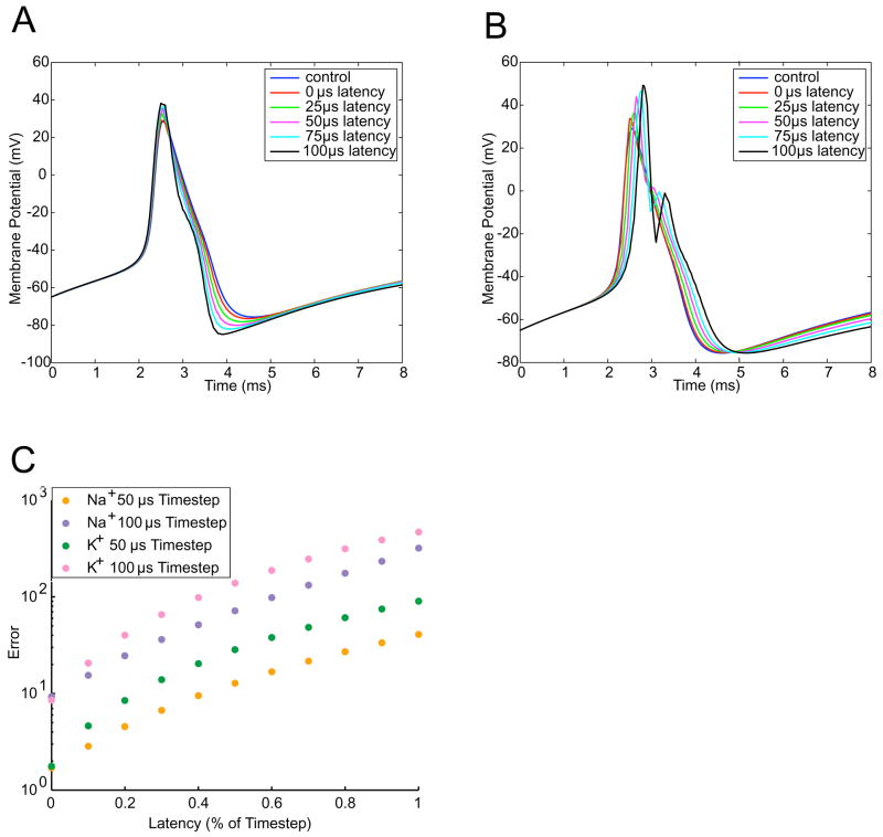
We next examined the effects of latency on dynamic clamp performance. We define latency as the time is takes for the system to generate an output based on the current time step’s inputs. Latency thus represents a lower bound on the possible time step. Figure 5 shows the error as a function of the latency. As one might expect, error increased with increased latency, even with the time step fixed. However, less intuitive is that virtual K+ channels (Fig. 5B) are more adversely affected by latency than virtual Na+ channels. This is because Na+ channels inactivate. Thus, the latency only slightly delays the rising edge of the action potential. K+ channels are affected throughout the course of the action potential. In the falling phase of the action potential, long-latency K+ channels led to double-peaks, an indication of instability. Long-latency K+ channels also lead to gross distortions of the afterhyperpolarization.
Figure 5. Effects of system latency on dynamic clamp accuracy.
In experiments involving virtual Na+ (A) and K+ (B) channels, we introduced latency in experiments conducted with a time step of 100μ. C: Summary data from manipulations of latency. For a given time step, the latency makes a substantial difference in the level of error.
Firing rate – current relationship
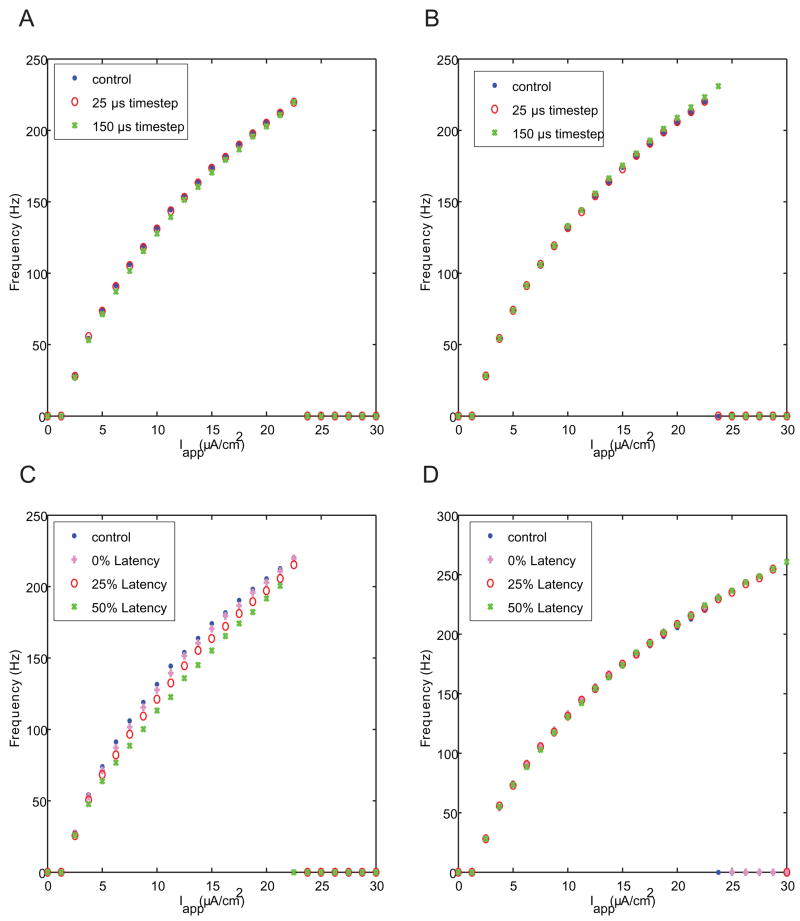
To study the impact of imperfect dynamic clamping on spike trains, we evaluated changes in firing frequency in response to various DC current inputs. Despite the substantial affect that time step has on action potential shape (Fig. 3), it has only small effects on the frequency-vs.-current (F–I) curve when virtualizing Na+ (Fig. 6A) or K+ (Fig. 6B) channels. Virtualizing K+ channels with long time steps does extend the F–I curve to slightly higher values of current and firing rate. This effect occurs because as the virtualized K+ channels are updated more slowly, they lead to longer afterhyperpolarizations, allowing Na+ channels to de-inactivate more completely. Thus, long time steps for K+ channel virtualization make the cell slightly more resistant to depolarization block.
Figure 6. Effects of time step and latency on firing rate in dynamic clamp simulations.
Plots show firing rate vs. applied current for virtualized Na+ (A, C) and K+ (B, D) channels. In general, effects on firing rate were less dramatic than those on spike shape (Figs. 3, 5).
Latency in Na+ channel virtualization (Fig. 6C) causes a leftward shift in the f-I curve as well as a decrease in the maximum firing rate. Latency in the K+ channel response has no effect on the FI curve until the right-hand side. At that point, long latencies, like long time steps, make the model more resistant to depolarization block.
Brain slice experiments
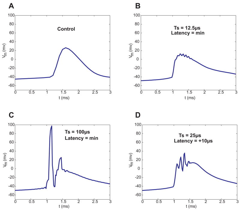
To verify that results from the simulated dynamic clamp experiments hold true in actual experiments, a high speed software-based dynamic clamp system was constructed. This stripped-down system provided very precise control over the timing of input and output. A CA1 pyramidal cell was patch-clamped and 1μM TTX was applied to the bath to knock out Na+ channels. Virtual Na+ channels were then re-introduced using dynamic clamp. A single action potential was induced by injecting a 10ms, 0.5nA pulse of current. To compensate for bistability caused by knocking in a large Na+ conductance away from the axon hillock, additional KDR+ conductance was also added. Without the additional KDR+, the cell would fire one action potential then latch up in a depolarized state. Enough KDR+ was added to allow the cell to fire action potentials and return to rest (~−50mV for the cell shown; data are not corrected for the junction potential). Effects of time step and latency were qualitatively similar to those seen in simulated experiments (Figure 7). The experiments with a real neuron were slightly more sensitive to dynamic clamp performance than predicted by the simulations. For example, a time step of duration 100μs produced errors similar to a simulated 200μs time step (Figure 7C). The biological system was also subtantially more sensitive to increased latency than was the modeled system.
Figure 7. Whole-cell patch-clamp recordings demonstrate the effects of time step (Ts) and latency under real-world conditions.
In measurements from CA1 pyramidal cells, we recorded action potentials under control conditions (A) and with virtualized Na+ channels (B). We also introduced long time steps (C) and latencies (D). Effects in experiments were qualitatively similar to those in simulations, but experimental data were more sensitive to inaccuracies than were simulated data from previous figures.
Even under the best-case real-world scenario (Fig. 7B), action potentials are distorted relative to control conditions (Fig. 7A). Several factors no doubt contribute to this discrepancy. First, our model of Na+ channels is no doubt not entirely accurate. Second, under dynamic clamp, we introduce the virtual Na+ channels into the soma alone; biological Na+ channels are spatially distributed and concentrated near the axon hillock. Third, in sampling voltage and feeding back current, dynamic clamp experiments are subject to additional errors due to anti-alias filtering, ambient and digitization noise, and incomplete compensation for series resistance and electrode capacitance. We are not certain which of these sources of error are most responsible for the increase in the rising slope of the action potential we see in dynamic clamp.
Discussion
The data from these simulations and experiments demonstrate the key role time step duration, latency, and differential equation solver method have on dynamic clamp performance. For the two conductances studied here, Na+ and K+, these effects tended to manifest themselves as distortions of the action potential, but did not generally effect the firing frequency of the cell. Perhaps the most important finding is that a system capable of 50 μs worst case time steps with latency of no more than 25% of the time step, 12.5 μs, is theoretically sufficient for conducting one of the most intensive of experiments, Na+ channel virtualization. However, observed differences between the point model simulation and physical experiments indicate that timing benchmarks need to be better than theoretical predictions.
Our method should be useful to developers and users of dynamic clamp systems in several regards. First, we provide estimates of the amount of error that one can get away with in dynamic clamp experiments. Under real-world conditions, our results suggest that clock speeds greater than 10 kHz (time steps < 0.1 ms) and minimal latencies are required to mimic mammalian Na+ channels accurately. Although time-step-induced errors in virtualization of K+ channels are often less dramatic than those in virtualization of Na+ channels, a reasonable match to control conditions still requires clock rates > 10 kHz (Fig. 3). Second, we show templates of how particular sources of error affect action potential shape. Assuming that these templates hold in general, they provide hints to experimentalists regarding what sources of error may lie in their data, and how those errors may be corrected. In this vein, we note that errors due to slow time steps in virtualization of K+ channels are subtle, affecting mainly the afterhyperpolarization; for this reason, even large errors induced in introducing virtual K+ channels could easily be missed. Finally, our method provides a general framework by which others may wish to evaluate their dynamic clamp systems.
Our results suggest that software-based systems are sufficient for many purposes in dynamic clamp systems. Existing software-based “hard” real-time systems are based around extensions of the Linux operating system (e.g., Dorval et al., 2001; Raikov et al., 2004) can operate at sufficient clock rates for these purposes. Additionally, they have the advantage of highly constrained worst-case performance. As we have seen (Fig. 4), worst-case performance is crucial in determining system fidelity. Windows-based systems (e.g., Nowotny et al., 2006) in general give a high level of performance. However, these systems have rare, but inevitable, “long” time steps (e.g., 0.76 ms in benchmarking done by Nowotny et al., 2006). From our work we conclude that Windows-based systems are generally sufficient, but will induce catastrophically bad behavior on some occasions. We recommend that users of Windows-based systems use independent means to determine the jitter in their time steps (Nowotny et al., 2006) and discard data that are corrupted by long time steps. Additionally, we urge all dynamic clamp developers and users to consider the issue of latency, which our results show has dramatic effects on system performance.
Acknowledgments
We are grateful to A.D. Dorval and T. I. Netoff for helpful discussions in developing this work. Supported by grants from the National Institute for Research Resources, the National Institute for Neurological Diseases and Stroke, and the National Institute for Mental Health.
Footnotes
Publisher's Disclaimer: This is a PDF file of an unedited manuscript that has been accepted for publication. As a service to our customers we are providing this early version of the manuscript. The manuscript will undergo copyediting, typesetting, and review of the resulting proof before it is published in its final citable form. Please note that during the production process errors may be discovered which could affect the content, and all legal disclaimers that apply to the journal pertain.
Literature Cited
- Butera RJ, Jr, Wilson CG, Delnegro CA, Smith JC. A methodology for achieving high-speed rates for artificial conductance injection in electrically excitable biological cells. IEEE transactions on biomedical engineering. 2001;48:1460–70. doi: 10.1109/10.966605. [DOI] [PubMed] [Google Scholar]
- Dorval AD, Christini DJ, White JA. Real-Time linux dynamic clamp: a fast and flexible way to construct virtual ion channels in living cells. Annals of biomedical engineering. 2001;29:897–907. doi: 10.1114/1.1408929. [DOI] [PubMed] [Google Scholar]
- Kullmann PH, Wheeler DW, Beacom J, Horn JP. Implementation of a fast 16-Bit dynamic clamp using LabVIEW-RT. Journal of neurophysiology. 2004;91:542–54. doi: 10.1152/jn.00559.2003. [DOI] [PubMed] [Google Scholar]
- Migliore M, Hoffman DA, Magee JC, Johnston D. Role of an A-type K+ conductance in the back-propagation of action potentials in the dendrites of hippocampal pyramidal neurons. Journal of computational neuroscience. 1999;7:5–15. doi: 10.1023/a:1008906225285. [DOI] [PubMed] [Google Scholar]
- Netoff TI, Banks MI, Dorval AD, Acker CD, Haas JS, Kopell N, White JA. Synchronization in hybrid neuronal networks of the hippocampal formation. Journal of neurophysiology. 2005;93:1197–208. doi: 10.1152/jn.00982.2004. [DOI] [PubMed] [Google Scholar]
- Nowotny T, Szucs A, Pinto RD, Selverston AI. StdpC: a modern dynamic clamp. Journal of neuroscience methods. 2006;158:287–99. doi: 10.1016/j.jneumeth.2006.05.034. [DOI] [PubMed] [Google Scholar]
- Pinto RD, Elson RC, Szucs A, Rabinovich MI, Selverston AI, Abarbanel HD. Extended dynamic clamp: controlling up to four neurons using a single desktop computer and interface. Journal of neuroscience methods. 2001;108:39–48. doi: 10.1016/s0165-0270(01)00368-5. [DOI] [PubMed] [Google Scholar]
- Prinz AA, Abbott LF, Marder E. The dynamic clamp comes of age. Trends in neurosciences. 2004;27:218–24. doi: 10.1016/j.tins.2004.02.004. [DOI] [PubMed] [Google Scholar]
- Raikov I, Preyer A, Butera RJ. MRCI: a flexible real-time dynamic clamp system for electrophysiology experiments. Journal of neuroscience methods. 2004;132:109–23. doi: 10.1016/j.jneumeth.2003.08.002. [DOI] [PubMed] [Google Scholar]
- Robinson HP, Kawai N. Injection of digitally synthesized synaptic conductance transients to measure the integrative properties of neurons. Journal of neuroscience methods. 1993;49:157–65. doi: 10.1016/0165-0270(93)90119-c. [DOI] [PubMed] [Google Scholar]
- Scott S. Stimulation simulations of young yet cultured beating hearts. State University of New York at Buffalo; Buffalo, NY: 1979. [Google Scholar]
- Shampine LF, Reichelt MW. The MATLAB ODE suite. SIAM J Sci Comput. 1997;18:1–22. [Google Scholar]
- Sharp AA, O’Neil MB, Abbott LF, Marder E. Dynamic clamp: computer-generated conductances in real neurons. Journal of neurophysiology. 1993;69:992–5. doi: 10.1152/jn.1993.69.3.992. [DOI] [PubMed] [Google Scholar]
- Tan RC, Joyner RW. Electrotonic influences on action potentials from isolated ventricular cells. Circulation research. 1990;67:1071–81. doi: 10.1161/01.res.67.5.1071. [DOI] [PubMed] [Google Scholar]
- Tateno T, Robinson HP. Rate coding and spike-time variability in cortical neurons with two types of threshold dynamics. Journal of neurophysiology. 2006;95:2650–63. doi: 10.1152/jn.00683.2005. [DOI] [PubMed] [Google Scholar]


