Abstract
Gold nanoparticles covalently attached to the indium tin oxide coated glass slide drastically quench fluorescence of a surface immunoassay (approximately 5-fold). Silver electrochemically deposited over the gold particles leads to fluorescence amplification: signal increases approximately 7–8 times if compared to the signal on gold particles not covered with silver. This phenomenon allows enhancing of the surface immunoassays utilizing both types of nanoparticles.
1. Introduction
Nanoparticles, in particular gold and silver, are widely used in various kinds of assays, mostly as labels [1–3]. In many cases, strong quenching of a fluorophore is observed near gold nanoparticles of 1–100 nm size [4–7]. However, in some cases no quenching [8] (at specific fluorophore orientation on the gold nanoparticle surface), or fluorescence enhancement [9–11] is observed. Fluorophore emission near gold particles depends on the location of the dye near the particle, the fluorophore-particle surface distance, and molecular dipole orientation versus particle surface [12–14].There are various effects observed on gold particles attached to a glass substrate: for example, less quenching [15] or enhancement [16].
In this Letter we report manipulation of the fluorescence signal from the surface immunoassay achieved by using coating the surface with gold nanoparticles, which may be further covered by silver shells.
2. Experimental
2.1. Materials
Hydrogen tetrachloroaurate(III) triahydrate and sodium citrate were both obtained from Aldrich and used to prepare the 12 nm colloidal gold sol. Corning 1737 aluminosilicate glass, 7 x 50 x 0.7mm, coated with indium tin oxide (ITO) (Rs = 5–15 Ω) was purchased from Delta Technologies, Ltd (Stillwater, MN). Sodium hydroxide, glacial acetic acid, and aminopropyltriethoxysilane, all obtained from Aldrich, were used to prepare gold nanoparticle – ITO hybrid electrodes. Silver nitrate, obtained from Sigma-Aldrich, and ammonium hydroxide, obtained from Fisher, were used for silver deposition on the hybrid electrode. Rabbit and goat immunoglobilins (IgGs) (95% pure) were from Sigma. Labeled-anti-rabbit IgG was from Invitrogen (stock solution 2 mg/mL, label Rhodamine Red-X, label:protein ratio 3.7 mol/mol). Buffer components and salts used in the assay (such as bovine serum albimun, poly-L-lysine, glucose, sucrose, sodium phosphate) were from Sigma-Aldrich.
2.2. Preparation of gold nanoparticle – ITO slides
A colloidal gold sol in water (ca. 17 nM) was prepared by reduction of hydrogen tetrachloroaurate(III) trihydrate with sodium citrate as reported previously [17]. It was verified that colloidal gold nanoparticles were monodisperse (ca. 12–13 nm) using UV-visible specta [17]. The gold nanoparticles were covalently attached to ITO slides as previously described [18]. Briefly, the ITO slides were scrupulously washed with soap (Alconox) and rinsed with distilled water, then slides were soaked overnight in 0.1 M NaOH to activate the surface, rinsed copiously with distilled water, and soaked overnight at 80–90°C in a solution of 5% (v/v) aminopropyltriethoxysilane in 0.1 M acetic acid (pH 5.5). Next, slides were rinsed plentifully with deionized water, air dried, and placed into a petri dish with ITO side-up for drop coating with colloidal gold sol. About 400 μL of the colloidal gold sol was drop coated on the desired area of the ITO slide. The excess of colloidal gold sol was rinsed with deionized water after the incubation for two hours at room temperature. The gold nanoparticle – ITO modified slides were air dried in vials and stable for several months.
2.3. Electrochemical silver deposition on gold nanoparticle – ITO slides
The electrochemical deposition of silver on ITO or gold nanoparticle-modified ITO electrodes was performed in the solution of 1 x10⁻³ M AgNO3 in 1.0 M NH4OH [19]. The electrochemical cell was assembled as shown in Figure 1A. The ITO or gold nanoparticle –ITO modified electrode (a) was used as a working electrode, Ag/AgCl (b), and platinum wire (c) were used as reference and auxiliary electrodes, respectively. The potential was held at −0.20V for 700s using Gamry PCI4 potentiostat. The gold nanoparticle – ITO modified slides with deposited silver, shown in Figure 1B, were air dried and stored in vials. The silver deposited slides were very uniform and stable.
Figure 1.
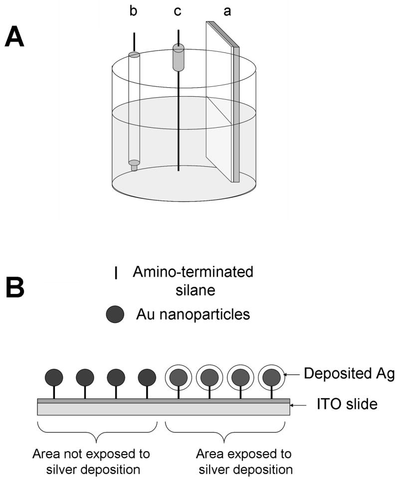
(A) The electrochemical cell for silver deposition with (a) ITO or gold nanoparticle –ITO modified working electrode, (b) Ag/AgNO3 reference electrode and (c) platinum auxiliary electrode. (B) The schematic representation of gold nanoparticle –ITO modified electrode with and without deposited silver.
2.4. Immunoassay procedure
Slides were covered with black electric tape (on the paper support) containing rectangular holes (3 x 30 mm) to form wells on the surface of the slides. Model immunoassays were performed on the slide surface in the wells as described earlier [20]. Briefly, rabbit IgG was non-covalently immobilized on the “sample” slide, or goat IgG on the “control” slide. Then, Rhodamine Red-X-labeled anti-rabbit IgG conjugate was added to the sample slide (with rabbit IgG) or control slide (with goat IgG) and after incubation (1 hr at room temperature) and washing, the fluorescence signal was measured.
2.5. Spectroscopic measurements
Emission spectra in solution were measured using a Varian Cary Eclipse fluorometer (“Varian Analytical Instruments”, USA). Absorption spectra in solution and on the surface of the slides were measured using a Cary 50 spectrofotometer (Varian, Inc.). Fluorescence measurements of the samples on slide surfaces were performed in total internal reflection (TIRF) mode by placing the slides horizontally on a coupling prism [20]. For excitation we used a small solid state laser with emission at 532 nm laser diode. Emission spectra were collected via a fiber optic from the top of the sample. For observation we used appropriate long wave pass cut-off filters to attenuate excitation lines.
The enhancement or quenching ratio was calculated as a ratio of (average particle-coated slide signal) to (average non-coated slide signal). The signal for a single spot was taken as the average of the fluorescence signal at the emission maximum (5 data points). For all reported intensities we averaged the signal from 5 different spot locations on the slide.
Atomic Force Microscopy (AFM) images were collected by scanning dry sample slides with an Atomic Force Microscope (TMX 2100 Explorer SPM, Veeco), equipped with AFM dry scanner, over 100 μm. The AFM scanner was calibrated using a standard calibration grid as well as 100 nm diameter gold nanoparticles, from Ted Pella. Images were analyzed using SPMLab software.
Results and Discussion
We present here the results of the model immunoassay performed on the surface coated with various types of nanoparticles: gold only, gold coated with silver shell and silver only. We expect quenching effect for gold only nanoparticles and enhancement for silver only nanoparticles; our goal was to compare different types of particles and demonstrate their utilization for surface immunoassays when the change of the fluorescence intensity is being recorded.
There are three major effects influencing the fluorescence emission near the metallic surface.
First, in a close proximity to the metallic surface, the fluorophores are strongly quenched. The excitation energy is dumped to the metal without further emission. In the case of gold nanoparticles, the quenching is more pronounced than for silver, due to absorptive properties of metals. Gold nanoparticles, when being used in immunoassays, often just serve as strongly absorbing labels [21]. Many immunoassays using gold nanoparticles are based on strong fluorescence quenching near the particle surface [5, 22]. Larger gold nanoparticles and clusters may enhance the surface fluorescence [11, 16]. Second, as a result of illumination of metallic nanoparticles by the excitation light, there is an enhanced local field. This effect can be very strong as observed in a surface enhanced Raman scattering (SERS) [23–25]. Third, the near-field interaction of excited molecule with metallic nanoparicle may results in a rapid emission radiation. This effect is equivalent with an increase of radiative rate. As a consequence, the quantum yield of the fluorophore increases and the lifetime decreases.
The total brightness of fluorophores deposited on the metallic surface depends on the combination of these three effects. In some cases, very low analyte concentrations can be detected on the surface only in presence of silver colloid nanoparticles [26]. It should be noted, that shorter lifetime reduces potential photodegradation of fluorophore [27–29].
Enhancement ratio caused by silver nanoparticles strongly depends on the size and shape of the particles; ratios from few times up to 10–20 times, depending on the particle size and the fluorophore used, have been observed [20, 30].
It is known that gold nanoparticles catalyze reaction of silver deposition (silver shell formation over the gold nanoparticles); such combination of gold nanoparticles and silver coating has been used for assay enhancement [31–34]. Enhancement was observed at various types of detection, such as chemiluminescent detection of the Ag+ ions after oxidation of the silver shells [31], electrochemical detection of the Ag+ ions after oxidation of the silver shells [32], or optical detection of the Au/Ag particles after silver deposition on the gold [33–34] while nanoparticles have been used as labels for reporter antibodies.
We deposited small gold nanoparticles on ITO-coated slides. Then, silver was deposited over gold on some of the gold-ITO-coated slides (see Figure 1). As controls we also deposited silver on ITO-coated slides without gold particles. Additional controls for our immunoassay were slides without particles and with or without ITO coating.
The size of the gold particles in solution was determined by absorbance spectra (Figure 2) and found to be approximately 13 nm, according to spectra-size relation stated in [17]. These gold particles were used for deposition on the surface, as gold only particles, and gold particles with silver shells over them.
Figure 2.
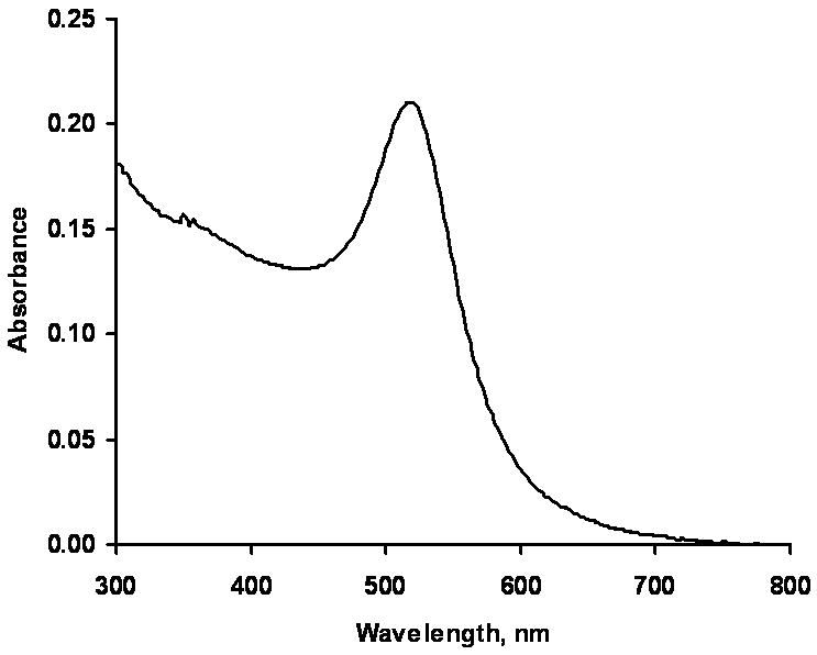
Solution spectrum of the gold nanoparticles.
Surface AFM images of gold, silver, and gold with silver shells particles are shown on Figure 3. Gold only particles are small and mostly are not detectable on the surface; however, on some parts of the surface they form aggregates shown on Figure 3A. Silver only particles mostly form aggregates (larger in size than gold ones) on the slide surface (Figure 3B). When silver is immediately coated over the gold on the slide surface, small gold seeds catalyze the formation of the silver shells, and the resulting particles are smaller in size (if compared to silver only deposition) and more uniform (Figure 3C). Approximate dimensions of the aggregates on slide 3B are 1 micron in diameter and about 300 nanometer height, while an averaged size of the particles on slide 3C is 200 nm in diameter and 70 nm height, suggesting that silver shell formation over the gold particles provides more stability and uniformity for particles with dual silver-gold metallic layer.
Figure 3.
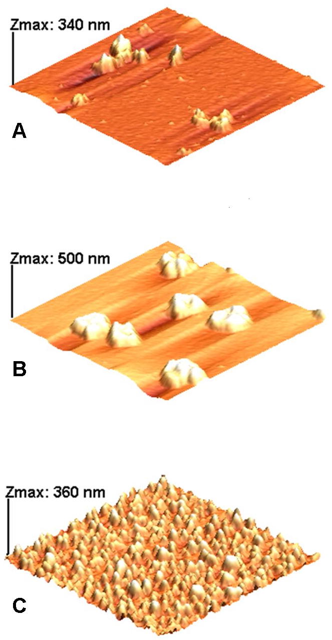
AFM images of samples: A –ITO/glass + Au particles; B – ITO/glass + Ag particles; C -ITO/glass + Au/Ag particles. X-Y dimensions for all scans are 5 x 5 μm.
Immunoassay detection was performed on the slide surface in TIRF mode as described in Materials and Methods section [20]. Fluorescence spectra of the bound reporter labeled antibodies measured on various surfaces are presented on Figure 4. They are characteristic for the fluorescence emission of used Rhodamine Red-X label. We see the quenching effect by gold only particles and enhancement for silver only particles, which confirms our suggestion and published data. We see also enhancement – nearly same as for silver only – in case of gold nanoparticles with the deposited silver coating over them (Figure 3). We verified these phenomena by repeated experiments, and summary immunoassay data are presented on Figure 5. For clearer presentation we normalized here all data to the signal from glass surface without any particles and even without ITO coating: average signal from this surface was taken as 1. These data are also corrected for the non-specific binding signal measured from the slides with “wrong” antigen (goat IgG, see Experimental) which was measurable but low (2% or less compared to specific signal).
Figure 4.
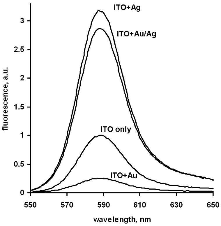
Fluorescence spectra of the model immunoassay signal (reporter Rhodamine Red-X antibodies) measured from different particle coatings of the ITO/glass slides (excitation by 532 nm laser).
Figure 5.
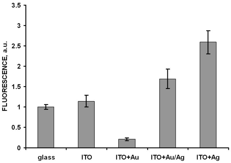
Fluorescence signals of the model immunoassay (reporter Rhodamine Red-X antibodies) measured from different particle coatings of the ITO/glass slides (excitation by 532 nm laser) and glass without ITO (takes as comparison signal of 1 a.u.). Error bars represent plus/minus one standard deviation (n=5).
We believe that such signal manipulation can be utilized in surface immunoassays where different antibodies are bound to different types of nanoparticles, which will result into drastic change of the fluorescence signal after addition of the analyte of interest. For example, antibody against analyte of interest can be immobilized on “gold only” particles. After saturation of this antibody with analytefluorophore conjugate and washing, fluorophore fluorescence will be quenched. Then after adding of the sample with analyte of interest, this analyte will replace the conjugate, and conjugate will detach from the gold particles and fluorescence will be restored (proportionally to the sample analyte concentration). Now if we combine “gold only” coated surface with the surface coated with silver-shelled gold, containing immobilized antifluorophore antibodies, after adding sample analyte conjugate from the solution will bind to this area of the surface, and fluorophore fluorescence will be increased (Figure 6). Here we expect higher enhancement values, since in this case fluorophore will be closer to the silver surface than in our model immunoassay experiment.
Figure 6.

Surface assay utilizing fluorescence signal manipulation on different nanoparticles. Antibody against analyte of interest is immobilized on “gold only” particles, and analyte-fluorophore conjugate is bound on this surface (fluorophore fluorescence is quenched). Then after adding of the sample with analyte of interest (black rhombs), this analyte will replace the conjugate, and conjugate will detach from the gold particles and fluorescence will be restored (proportionally to the sample analyte concentration). By transferring the supernatant solution onto a surface coated with silver-shelled gold, containing immobilized anti-fluorophore antibodies, we further enhance the conjugate fluorescence due to it’s binding to the silver-coated “enhancing” particles.
The advantage of such type of immunoassays is positive dose-response curve for a competitive immunoassay. This is especially important for small analytes such as drugs or pesticides which can not be detected in sandwich type immunoassays (with positive dose-response corves) because they have only one binding site.
Conclusion
We demonstrated that the quenching of fluorescence by gold can be reversed to a significant enhancement by the electrochemical coating of the surface with silver nanoparticles.
Silvering of the gold-nanoparticle-coated surface results into approximately 8-fold signal enhancement. We believe that such signal manipulation can be utilized in surface immunoassays where different antibodies are bound to different types of nanoparticles, which will result into drastic enhancement of the fluorescence signal and positive dose-response curve for competitive immunoassays.
Acknowledgments
This work was supported by Texas Emerging Technologies Fund grant, NIH HG 004364, NSF (DBI-0649889), and Welch Foundation (BP-0037).
Footnotes
Publisher's Disclaimer: This is a PDF file of an unedited manuscript that has been accepted for publication. As a service to our customers we are providing this early version of the manuscript. The manuscript will undergo copyediting, typesetting, and review of the resulting proof before it is published in its final citable form. Please note that during the production process errors may be discovered which could affect the content, and all legal disclaimers that apply to the journal pertain.
References
- 1.Nath N, Chilkoti A. J Fluorescence. 2004;14:377. doi: 10.1023/b:jofl.0000031819.45448.dc. [DOI] [PubMed] [Google Scholar]
- 2.Schultz DA. Curr Opin Biotechnol. 2003;14:13. doi: 10.1016/s0958-1669(02)00015-0. [DOI] [PubMed] [Google Scholar]
- 3.Csaki A, Moller R, Fritzsche W. Expert Rev Mol Diagn. 2002;2:187. doi: 10.1586/14737159.2.2.187. [DOI] [PubMed] [Google Scholar]
- 4.Ghosh SK, Pal A, Kundu S, Nath S, Pal T. Chem Phys Lett. 2004;395:366. [Google Scholar]
- 5.Kato N, Caruso F. J Phys Chem B. 2005;109:19604. doi: 10.1021/jp052748f. [DOI] [PubMed] [Google Scholar]
- 6.Ray PCh, Fortner A, Griffin J, Kim ChK, Singh JP, Yu H. Chem Phys Lett. 2005;414:259. [Google Scholar]
- 7.Schneider G, Decher G, Nerambourg N, Praho R, Werts MH, Blanchard-Desce M. Nano Lett. 2006;6:530. doi: 10.1021/nl052441s. [DOI] [PubMed] [Google Scholar]
- 8.Hernandez FE, Yu Sh, Garcia M, Campiglia AD. J Phys Chem B. 2005;109:9499. doi: 10.1021/jp050803e. [DOI] [PubMed] [Google Scholar]
- 9.Kühn S, Håkanson U, Rogobete L, Sandoghdar V. Phys Rev Lett. 2006;97:017402. doi: 10.1103/PhysRevLett.97.017402. [DOI] [PubMed] [Google Scholar]
- 10.Praharaj S, Ghosh SK, Nath S, Kundu S, Panigrahi S, Basu S, Pal T. J Phys Chem B. 2005;109:13166. doi: 10.1021/jp051132n. [DOI] [PubMed] [Google Scholar]
- 11.Bharadwaj P, Anger P, Novotny L. Nanotechnology. 2007;18:044017. [Google Scholar]
- 12.Barnes WL. J Mod Opt. 1998;45:661. [Google Scholar]
- 13.Enderlein J. Chem Phys. 1999;247:1. [Google Scholar]
- 14.Barnes WL, Dereux A, Ebbesen TW. Nature. 2003;424:824. doi: 10.1038/nature01937. [DOI] [PubMed] [Google Scholar]
- 15.Levi SA, Mourran A, Spatz JP, van Veggel FCJM, Reinhoudt DN, Möller M. Chem Eur J. 2002;8:3808. doi: 10.1002/1521-3765(20020816)8:16<3808::AID-CHEM3808>3.0.CO;2-6. [DOI] [PubMed] [Google Scholar]
- 16.Aslan K, Malyn SN, Geddes ChD. J Fluoresc. 2007;17:7. doi: 10.1007/s10895-006-0149-x. [DOI] [PubMed] [Google Scholar]
- 17.Keating CD, Musick MD, Keefe MH, Natan MJ. J Chem Ed. 1999;76:949. [Google Scholar]
- 18.Richardson JN, Aguilar Z, Kaval N, Andria SE, Shtoyko T, Seliskar CJ, Heineman WR. Electrochim Acta. 2003;48:4291. [Google Scholar]
- 19.Lee TM-H, Cai H, Hsing I-M. Electroanalysis. 2004;16:1628. [Google Scholar]
- 20.Matveeva E, Gryczynski Z, Malicka J, Gryczynski I, Lakowicz JR. Anal Biochem. 2004;334:303. doi: 10.1016/j.ab.2004.08.034. [DOI] [PMC free article] [PubMed] [Google Scholar]
- 21.Dykman LA, Bogatyrev VA, Khlebtsov BN, Khlebtsov NG. Anal Biochem. 2005;341:16. doi: 10.1016/j.ab.2005.03.010. [DOI] [PubMed] [Google Scholar]
- 22.Peng Z, Chen Z, Jiang J, Zhang X, Shen G, Yu R. Anal Chim Acta. 2007;583:40. doi: 10.1016/j.aca.2006.10.006. [DOI] [PubMed] [Google Scholar]
- 23.Jeanmaire DL, Van Duyne RP. J Electroanal Chem. 1977;84:1. [Google Scholar]
- 24.Kneipp K, Kneipp H, Itzkan I, Dasari RR, Feld MS. Curr Sci. 1999;77:915. [Google Scholar]
- 25.Nie S, Emory SR. Science. 1997;275:1102. doi: 10.1126/science.275.5303.1102. [DOI] [PubMed] [Google Scholar]
- 26.Lochner N, Lobmaier C, Wirth M, Leitner A, Pittner F, Gabor F. Eur J Pharmaceutics Biopharmaceutics. 2003;56:469. doi: 10.1016/s0939-6411(03)00115-2. [DOI] [PubMed] [Google Scholar]
- 27.Lakowicz JR, Shen Y, D’Auria S, Malicka J, Fang J, Gryczynski Z, Gryczynski I. Anal Biochem. 2002;301:261. doi: 10.1006/abio.2001.5503. [DOI] [PMC free article] [PubMed] [Google Scholar]
- 28.Malicka J, Gryczynski I, Maliwal B, Fang J, Lakowicz JR. Biopolymers. 2003;72:96. doi: 10.1002/bip.10301. [DOI] [PubMed] [Google Scholar]
- 29.Muthu P, Gryczynski I, Gryczynski Z, Talent J, Akopova I, Jain K, Borejdo J. Anal Biochem. 2007;366:228. doi: 10.1016/j.ab.2007.04.014. [DOI] [PMC free article] [PubMed] [Google Scholar]
- 30.Corrigan TD, Guo S, Phaneuf RJ, Szmacinski H. J Fluorescence. 2005;15:777. doi: 10.1007/s10895-005-2987-3. [DOI] [PubMed] [Google Scholar]
- 31.Li ZP, Liu CH, Fan YS, Wang YC, Duan XR. Anal Biochem. 2006;359:247. doi: 10.1016/j.ab.2006.09.030. [DOI] [PubMed] [Google Scholar]
- 32.Chu X, Fu X, Chen K, Shen GL, Yu RQ. Biosens Bioelectron. 2005;20:1805. doi: 10.1016/j.bios.2004.07.012. [DOI] [PubMed] [Google Scholar]
- 33.Csáki A, Kaplanek P, Möller R, Fritzsche W. Nanotechnology. 2003;14:1262. doi: 10.1088/0957-4484/14/12/006. [DOI] [PubMed] [Google Scholar]
- 34.Gupta S, Huda S, Kilpatrick PK, Velev OD. Anal Chem. 2007;79:3810. doi: 10.1021/ac062341m. [DOI] [PubMed] [Google Scholar]


