This review outlines questions to consider when attempting to solve crystal structures by molecular replacement.
Keywords: bioinformatics, molecular replacement, validation
Abstract
This review addresses the essential questions to consider when attempting to phase a new crystal structure using molecular replacement. Sequence matching can suggest whether there is a suitable three-dimensional model available, but it is also important to analyse the model in order to find its likely oligomeric state and to establish whether there are likely to be domain movements. Once a solution has been found it must be refined, which can be challenging for low-homology models. There is a detailed discussion of structures used as examples for CCP4 tutorials.
1. Introduction
Most of the readers of this volume are probably structural biologists, with a bias towards biology rather than structure. The discipline of crystallography is now fairly mature and can provide semi-automated tools to determine a structure without requiring a detailed understanding of the technical procedures. Users want to understand how a particular macromolecule fits into the machinery of a living cell and knowledge of its three-dimensional geometry can illuminate this.
However, to obtain such a model we need firstly to understand the known biochemistry, secondly to obtain protein, grow a crystal and collect observable intensities, and thirdly either to determine some experimental phases to allow the first model to be built or to use molecular-replacement (MR) techniques to position a known model in the new cell and thus generate initial phases. The final stage is to refine this model to one most consistent with the observed data.
1.1. Tutorials
The examples I will discuss are used for molecular-replacement tutorial material available from CCP4.
Alexei Vagin and Andrey Lebedev have prepared a tutorial which is available as part of the MOLREP download from http://www.ysbl.york.ac.uk/~alexei/molrep.html#installation.
Martyn Winn and I prepared extra material for a workshop in China. It is available at http://www.ccp4.ac.uk/courses/china06/tutorials/mr_tutorial_first.html and http://www.ccp4.ac.uk/courses/china06/tutorials/mr_tutorial_advanced.html.
2. The known biochemistry
It is safe to assume that all structural projects begin with knowledge of the sequence of the molecule under study and hence its molecular weight. The first step in determining a structure is to search the available databases to see what is already known; without an existing three-dimensional model molecular replacement is not an option for structure solution and the experimental design will require the measurement of extra sets of observed intensities for the determination of phases.
There is now a wealth of sequence information available for many organisms and excellent bioinformatics tools for searching these sequence databases. Likely homologous models can be gleaned by matching the sequence to those of known structures. There are many web-based tools for this, several of which are described by other contributors. I will illustrate the approach using the MSDtarget tool from the European Bioinformatics Institute (EBI) Macromolecular Structure Division (MSD; http://www.ebi.ac.uk/msd). This returns a list of targets and a pairwise alignment for all likely models. More sophisticated multiple sequence-alignment tools are described in Barton (2008 ▶) and Schwarzerbacher et al. (2008 ▶).
There may well be several models available and it is possible to learn more about your system by analysing and comparing these. Again there are many tools available, but I will use the EBI MSD tool MSDfold, developed by Eugene Krissinel (Krissinel & Henrick, 2004 ▶). This matches the secondary-structure elements of all models to the selected target and aligns them. (It may well also find other examples with similar folds but lower sequence identity not found by MSDtarget.) When there is low sequence homology, the secondary-structure matching may give a slightly different sequence alignment to that based on sequence alone.
It is useful to inspect the overlap of these aligned models. This can reveal domain movement between one model and another and unless this is treated properly it can make it very difficult to obtain any MR solution. The aligned domains can be used as input for the existing MR programs that accept multiple overlapping copies
It is also important to follow up clues to the likely biological entity, e.g. does this protein form an oligomer? The EBI tool MSDpisa analyses this and returns a set of coordinates for the assembly, as well as reporting the buried surface area, hydrogen bonds and so on (Krissinel & Henrick, 2007 ▶).
2.1. Examples
2.1.1. Human S100 A12 (S100)
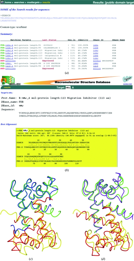
This structure has been deposited with PDB code 1e8a (Moroz et al., 2001 ▶). Some of the MSDtarget output obtained from the S100 sequence search is given in Fig. 1 ▶(a); Fig. 1 ▶(b) shows the pairwise matches. I will discuss models 1irj (41% sequence identity) and 1mho (39% sequence identity).
Figure 1.
Matching the S100 sequence against the EBI databases. (a) Some of the matching sequences found by the MSDtarget pairwise alignment. Those with associated three-dimensional models are shown in green. (b) The pairwise alignment for one of the models, 1irj. (c) The overlap, based on one chain only, of the final S100 dimer model, 1e8a, onto the 1irj dimer. The two chains of the S100 dimer are shown in green and blue and those of the 1irj dimer in yellow and tan. Clearly, the second chains do not match well. (d) The overlap of 1e8a onto the 1mho dimer using the same colour scheme. Although the matched chains do not fit so well, the relative orientation of the monomers is closer than that for 1irj.
MSDpisa indicates that both models are likely to be dimers with buried surface areas of 1282 and 1321 Å2, respectively. Figs. 1 ▶(c) and 1 ▶(d) show the alignment of these dimers. It is clear that their dimer interfaces are slightly different. A post mortem comparison of these models with the S100 structure shows that the root-mean-square (r.m.s.) difference in Cα positions of the monomers is 0.88 Å (1irj) and 1.23 Å (1mho), whilst for the 1irj dimer it is 2.64 Å and for the 1mho dimer it is 1.68 Å. If searching with a monomer 1irj would prove the better model, but if searching with a dimer the 1mho example is better. In practice, it is sensible to try all available models in all likely oligomeric states.
2.1.2. Sugar phosphotase in the closed form
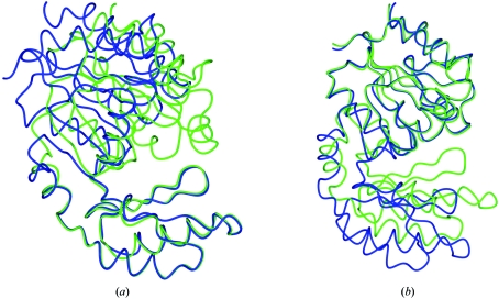
This structure has been deposited with PDB code 1tj3 (Fieulaine et al., 2005 ▶). There are several models with 100% sequence identity. However, there is clearly a hinged domain movement; the r.m.s. distance for Cα atoms between two of these models, 2d2v and 1s2o, is 2.4 Å. After overlapping the models (Figs. 2 ▶ a and 2 ▶ b), it is clear that there are two domains, one made up of residues 1–73 and 163–244, and another consisting of residues 74–162. In such a case it is necessary to search for a solution with each domain separately.
Figure 2.
The overlap of two models with 100% sequence identity to 1tj3. 2d2v is shown in green and 1s2o in blue. There is a hinged domain movement about residues 78–79 and 163–164. (a) The overlap based on residues 1–78 and 164–244. (b) The overlap based on residues 79–163.
2.1.3. Insulin
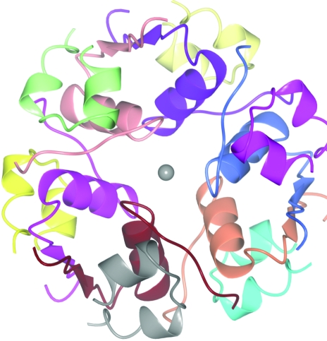
At high concentration and in the presence of a metal, insulin exists as a hexamer made up of three dimers each with two chemically identical monomers (Fig. 3 ▶). There are many crystal structures of insulin hexamers, some with one or more hexamers in the crystal asymmetric unit and some containing monomers or dimers, with the hexamer generated by crystal symmetry (Baker et al., 1988 ▶). An analysis of the contents of the asymmetric unit may suggest the likely stoichiometry and a self-rotation function may suggest the nature of the noncrystallographic symmetry. However, the interactions between crystallographic and noncrystallographic symmetry can become very complex.
Figure 3.
The insulin hexamer. Each of the 12 chains is shown in a different colour. The monomer unit is made up of two chains. Different structures have one monomer in the asymmetric unit (space groups P6322, H32, P321), a dimer in the asymmetric unit (H3, P213), a trimer (P41213) or a hexamer (P21)
2.1.4. Family 2 carbohydrate esterase (CE2)
This is a 345-residue protein solved by MR from a low-homology model. Some experimental phase information was also obtained from the anomalous scattering power of two Se atoms.
The MR solution was verified by checking it against the known selenium positions.
2.1.5. hypF
This crystal structure is of the prokaryotic hydrogenase maturation factor hypF acylphosphatase-like domain with a bound anion (Rosano et al., 2002 ▶). It was solved from experimental phases using a Hg derivative (the images were used for the data-processing tutorial described in http://www.mrc-lmb.cam.ac.uk/harry/imosflm/tutorial.html). It was later refined against 1.3 Å data and deposited with PDB code 1gxu.
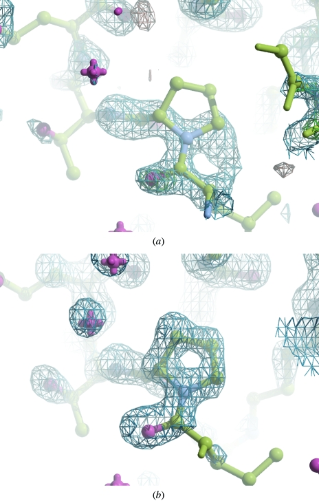
It can also be solved straightforwardly by MR using the model 1w2i with 38% sequence identity. I have included it to illustrate how the phase refinement carried out using the program ACORN (Yao et al., 2005 ▶) can improve the map and reduce the bias towards the initial model.
3. Planning the crystallography
While studying the bioinformatics information based on sequence, one hopes that a large crystal of the protein of interest is growing. The type of diffraction measurements required to solve the X-ray structure will depend to some extent on the chosen solution method. For experimental phasing, it is necessary to have a detectable substructure incorporated into the crystal, either anomalous scatterers or heavy atoms. Accurate measurements of the differences arising from that substructure to a limited resolution are needed to first position the substructure and then estimate experimental phases. For phase extension and refinement, we need the highest observable resolution plus complete low-resolution data. To solve the molecular replacement, a single complete data set to modest resolution is enough, but again the MR solution model must be refined and this is much more straightforward with higher resolution data.
If possible, it helps to use both the MR solution model and experimental phase information during the refinement step. These phases will not be biased towards the initial model and so can help when rebuilding and act as additional restraints to speed up refinement (Pannu et al., 1998 ▶).
As an aside, it is important to remember that when combining information from two (or more) diffraction experiments it is essential that the data sets are indexed according to the same convention and that the MR model and the substructure are positioned relative to the same origin. There is discussion of these conventions in the CCP4 program documentation. See http://www.ccp4.ac.uk/dist/html/reindexing.html and http://www.ccp4.ac.uk/dist/html/alternate_origins.html.
A simple way to achieve this is to calculate phases from the MR model and use these to produce anomalous or isomorphous difference maps with the data to be used for estimating experimental phases. If there are already more than one set of phases available, then the Clipper utility Phase Comparison (Cowtan, 2003 ▶) checks consistency and makes the appropriate corrections for any required origin shift or change of hand.
3.1. Assessing the quality of diffraction data
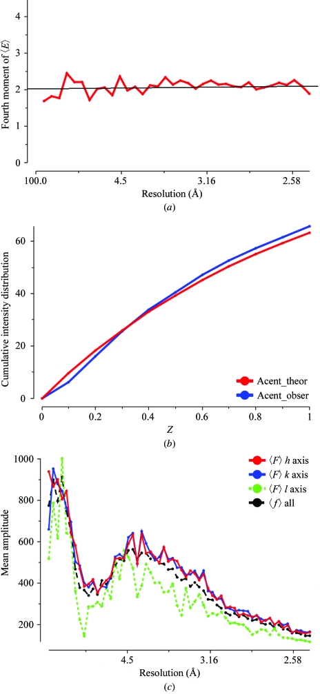
The diffraction experiment will reveal the unit-cell parameters and point group of our new crystal form. As for any X-ray study, it is important to assess the quality of the experimental data. It should be complete at low resolution and extend to the highest resolution available to help the refinement procedures. The data-reduction software gives some analysis of other problems which may arise. Is the crystal twinned? Is the diffraction very anisotropic? Fig. 4 ▶ shows various plots taken from the output of the TRUNCATE program which may indicate problems. There is a discussion of indicators of data quality at http://www.ccp4.ac.uk/dist/html/pxmaths/bmg10.html and of the effects of twinning at http://www.ccp4.ac.uk/dist/html/twinning.html. The program SFCHECK (Vaguine et al., 1999 ▶) is another tool for data analysis. As well as detecting anisotropy and possible twinning, it reports noncrystallographic translation.
Figure 4.
Quality indicators for the S100 intensity data used to solve the structure. These are all output from the TRUNCATE program. (a) The fourth moment plot of 〈E〉 for acentric data. This is approximately 2.0 across the whole resolution range, showing that the crystal is not seriously twinned. (b) The cumulative intensity distribution. The observed values agree well with the expected theoretical values. (c) An illustration of the anisotropic nature of the intensity distribution. The mean amplitude along the third axis is much weaker than that along the first and second.
3.2. Determining the space group
It is often not possible to assign a space group unambiguously at this stage. Absences along particular axes indicate screw axes, e.g. space group P21 will have absences for all 0k0 reflections where k is odd. However, any pseudo-translation vector (x, 0.5, z) will also cause the same reflections to have very weak intensities. There are other space groups where the enantiomorph generates the same systematic absences. Examples are space groups P41 and P43 or P61 and P65. The MR search should settle this uncertainty since one of the possible space groups should score significantly higher than any of the alternatives.
3.3. What can we estimate from sequence and diffraction?
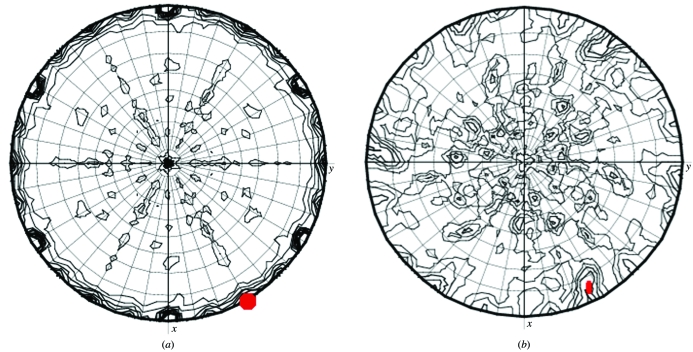
From the volume of the crystal asymmetric unit and the molecular weight of the protein, it is possible to estimate how many independent copies of the molecule under investigation are likely to be in the asymmetric unit. If there is more than one it is important to check whether there is a noncrystallographic symmetry element or a noncrystallographic translation vector relating them. Both these can be predicted from the X-ray data alone. If there is extra symmetry such as a noncrystallographic twofold axis, the self-rotation function may reveal it (Figs. 5 ▶ a and 5 ▶ b). However, this can be masked by crystal symmetry and be very confusing to interpret! Insulin studies illustrate this: the intersecting twofold and threefold axes of the hexamer are sometimes crystallographic and sometimes not and the asymmetric unit can consist of monomers, dimers, trimers or hexamers. There are examples of structures in many different space groups, e.g. H32 and P6322 with a monomer in the asymmetric unit, H3 and P213 with a dimer, P321 with three molecules in the asymmetric unit, a trimer on the twofold axis and a monomer at the 32 centre, and P21 with the whole hexamer in the asymmetric unit.
Figure 5.
Self-rotation sections for different κ values calculated using MOLREP. (a) κ = 180° sections for insulin data in space group P321. The crystallographic threefold axes are the maximum. The second peak on the κ = 180° section marked in red is generated by a noncrystallographic twofold axes of symmetry. The interaction of crystallographic and noncrystallographic symmetry generates many additional features. (b) κ = 180° sections for S100 data in space group H32. The noncrystallographic twofold axis of symmetry is marked in red. It is not a well defined peak and is distorted by its interaction with the crystallographic symmetry.
If there is a noncrystallographic translation the 4 Å native Patterson will have a large off-origin peak at the position representing this translation. Unlike noncrystallographic rotations, noncrystallographic translations are not particularly useful in structure determination. In fact, they introduce awkward structure-factor correlations that are not currently accounted for and can make structures difficult to refine.
4. Molecular-replacement techniques and software
The methodology is discussed by other authors in this issue.
5. Verifying the solution
As an aside, remember that it can be difficult to compare solutions from different programs, since the calculated amplitudes will be the same irrespective of any crystallographic symmetry operator applied to the solution or alternate choice of unit-cell origin. If phases are calculated from both models, the Clipper utility Phase Comparison will indicate whether the solutions are consistent after taking into account the choice of origin.
5.1. Space-group check
The MR search programs can be run in the several alternate space groups consistent with the point group. A good indicator is if there is a significantly better result in one space group than the others. (Different software uses different scoring functions, but all require a strong correlation between the observed and calculated amplitudes.)
5.2. Chemical sense
We need to check whether the model makes chemical sense. Are there many clashes between symmetry copies? Is the biological entity sensible? (This can be somewhat tricky to check from the MR solution alone; many MR search programs will position the correct number of molecules but not cluster them in the unit cell. Once again MSDpisa can be used to select the best assembly from the solution.) If there are several molecules in the asymmetric unit are they consistent with the self-rotation function? If you have some extra information such as possible positions for Se or S atoms, is this model consistent with it? (Remember to consider alternate origins and hands.)
5.3. Can the model be refined?
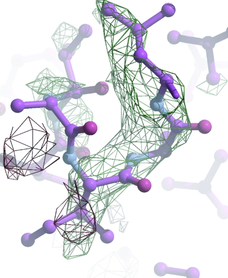
The usual check is that the solution model generates structure amplitudes which agree with the observed ones. Initial R values always seem to be high (typically R/free R of 55%/55% for me), but correct solutions will (usually!) refine automatically to an R/free R of about 40%/45%. The most encouraging verification is the electron density: if you can see features in the maps which are not part of the model, then the solution is probably substantially correct (Fig. 6 ▶).
Figure 6.
The first maximum-likelihood weighted electron-density map for S100 from the 1irj solution after ten initial rounds of refinement. The model had been truncated to remove many of the side chains. R and R free had fallen from 47.1% and 47.2% to 34.4% and 44.4%, respectively. Although the map is of poor quality, there is clear density for the Ile79 side chain.
6. Refinement tricks and bias elimination
There are still intractable problems in progressing from an initial MR solution to a final model which reflects the differences between the initial search molecule and that under investigation. There is no foolproof way of recognizing where the two models will differ and the initial maps will tend to mirror the partially incorrect input structure, especially if there is a paucity of experimental data. It is still sometimes necessary to rebuild the structure slowly into a series of weighted difference maps.
If the resolution is sufficient, automated rebuilding methods combined with maximum-likelihood weighted refinement can be very successful, rebuilding and correcting most of the molecule. ARP/wARP (described by Cohen et al., 2008 ▶) and RESOLVE (Terwilliger, 2002 ▶) are well established methods for automated rebuilding.
If the data resolution extends to 1.7 Å or better, density-modification procedures such as those programmed into ACORN can eliminate bias quickly and give excellent starting maps (Figs. 7 ▶ a and 7 ▶ b).
Figure 7.
Electron density maps for hypF using 1.3 Å data. (a) The first maximum-likelihood-weighted map showing the electron density near Pro85. After ten cycles of refinement, R and R free have fallen from 55.2% and 55.8% to 47.2% and 48.6%, respectively. (b) The ACORN map for Pro85 after automated phase refinement.
6.1. Ingenuity: use all your crystallographic knowledge
There are many interesting reports of structure solution which ingeniously combine different crystallographic techniques for obtaining the final model. I list some of them here for reference.
(i) Most structures include some weak anomalous scatterers such as S atoms. Providing the anomalous differences for the data set have been retained, it is easy to produce an ‘anomalous difference map’ using the measured anomalous differences and the phases calculated from the MR model. A peak search of such a map may (depending on the data quality) find the anomalous scattering sites. If so, this is very encouraging and can position some side chains, typically Cys and Met, unambiguously. It may indeed be possible to calculate experimental phases from these anomalous differences.
(ii) If there is more than one copy of the molecule in the asymmetric unit it is possible (and easy within the graphics program Coot; Emsley & Cowtan, 2004 ▶) to display averaged density, which is often easier to interpret. A single copy of the molecule is rebuilt into the averaged map and then copied back to the other positions. An extension of this method was used by Keller et al. (2006 ▶) to solve a structure with very low homology and near perfect noncrystallographic fourfold rotational symmetry. They used the phases based on the model to 5 Å only and successfully used density modification to extend and average phases to the resolution limit.
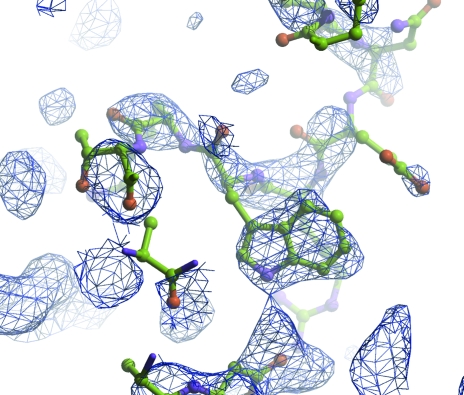
(iii) Victoria Money and colleagues in York have combined information from experimental phasing to verify a low-homology MR solution and to speed up rebuilding of a carbohydrate esterase (CE2; private communication). Initial phases had been calculated based on two Se atoms for 340 residues. These were not sufficient to give an interpretable map. The MR solution was also somewhat unclear, but the positions of the selenium-containing residues were consistent with those deduced from the anomalous data measurements. The truncated MR model was refined with the experimental phases as restraints and although this too generated a poor map, it was possible to position many of the side chains and to kick-start further refinement and rebuilding (Fig. 8 ▶).
(iv) If the model is flexible with several domains, it can help to break up any solution based on the whole model into domains and carry out a rigid-body refinement of these fragments to improve the initial fit. Such an approach is reported in Martinez-Fleites et al. (2005 ▶).
Figure 8.
CE2 experimentally phased electron-density maps with phases based on the weak Se anomalous signal. The molecular-replacement solution is superposed. The broken density for residue Trp239A clearly verifies the MR solution.
7. Conclusions
As more and more structural information becomes available, greatly improved bioinformatics tools are being developed to analyse and display it. Although molecular replacement is becoming automated, there is still a place for crystallographic and biological insight. In some cases this can be challenging; the interaction of different symmetry elements is often extremely complex. The final frontier of automating refinement of MR models has still not been reached.
Acknowledgments
This review rests heavily on the work of others. It borrows from tutorial material prepared by Airlie McCoy, Alexei Vagin, Andrey Lebedev and Martyn Winn. Members of the York Structural Biology Laboratory have provided data and valuable discussions. In particular, I would like to thank Olga Morez, Carlos Martinez-Fleites, David Lawson, Carmelo Rosano and Victoria Money for providing examples. Liz Potterton helped to prepare the figures using CCP4MG (Potterton et al., 2004 ▶).
References
- Baker, E. N., Blundell, T. L., Cutfield, J. F., Cutfield, S. M., Dodson, E. J., Dodson, G. G., Crowfoot Hodgkin, D. M., Hubbard, R. E., Isaacs, N. W., Reynolds, C. D., Sakabe, K., Sakabe, N. & Vijayan, N. M. (1988). Philos. Trans. R. Soc. London Ser. B, 319, 369–456. [DOI] [PubMed]
- Barton, G. J. (2008). Acta Cryst. D64, 25–32. [DOI] [PMC free article] [PubMed] [Google Scholar]
- Cohen, S. X., Ben Jelloul, M., Long, F., Vagin, A., Knipscheer, P., Lebbink, J., Sixma, T. K., Lamzin, V. S., Murshudov, G. N. & Perrakis, A. (2008). Acta Cryst. D64, 49–60. [DOI] [PMC free article] [PubMed] [Google Scholar]
- Cowtan, K. (2003). IUCr Comput. Commission Newsl.2, 4–9. http://www.iucr.org/iucr-top/comm/ccom/newsletters/2003jul/index.html.
- Emsley, P. & Cowtan, K. (2004). Acta Cryst. D60, 2126–2132. [DOI] [PubMed]
- Fieulaine, S., Lunn, J. E., Borel, F. & Ferrer, J.-L. (2005). Plant Cell, 17, 2049–2058. [DOI] [PMC free article] [PubMed]
- Keller, S., Pojer, F., Heide, L. & Lawson, D. M. (2006). Acta Cryst. D62, 1564–1570. [DOI] [PubMed]
- Krissinel, E. & Henrick, K. (2004). Acta Cryst. D60, 2256–2268. [DOI] [PubMed]
- Krissinel, E. & Henrick, K. (2007). J. Mol. Biol.372, 774–797. [DOI] [PubMed]
- Martinez-Fleites, C., Ortiz-Lombardia, M., Pons, T., Tarbouriech, N., Taylor, E. J., Hernandez, L. & Davies, G. J. (2005). Biochem. J.390, 19–27. [DOI] [PMC free article] [PubMed]
- Moroz, O. V., Antson, A. A., Murshudov, G. N., Maitland, N. J., Dodson, G. G., Wilson, K. S., Skibshøj, I., Lukanidin, E. M. & Bronstein, I. B. (2001). Acta Cryst. D57, 20–29. [DOI] [PubMed]
- Pannu, N. S., Murshudov, G. N., Dodson, E. J. & Read, R. J. (1998). Acta Cryst. D54, 1285–1294. [DOI] [PubMed]
- Potterton, L., McNicholas, S., Krissinel, E., Gruber, J., Cowtan, K., Emsley, P., Murshudov, G. N., Cohen, S., Perrakis, A. & Noble, M. (2004). Acta Cryst. D60, 2288–2294. [DOI] [PubMed]
- Rosano, C., Zuccotti, S., Bucciantini, M., Stefani, M., Ramponi, G. & Bolognesi, M. (2002). J. Mol. Biol.321, 785–796. [DOI] [PubMed]
- Schwarzenbacher, R., Godzik, A. & Jaroszewski, L. (2008). Acta Cryst. D64, 133–140. [DOI] [PMC free article] [PubMed] [Google Scholar]
- Terwilliger, T. C. (2003). Acta Cryst. D59, 38–44. [DOI] [PMC free article] [PubMed]
- Vaguine, A. A., Richelle, J. & Wodak, S. J. (1999). Acta Cryst. D55, 191–205. [DOI] [PubMed]
- Yao, J.-X, Woolfson, M. M, Wilson, K. S. & Dodson, E. J. (2005). Acta Cryst. D61, 1465–1475. [DOI] [PubMed]


