

Abstract
A technique for transperineal high-dose-rate (HDR) prostate brachytherapy and needle biopsy in a standard 1.5 T MRI scanner is demonstrated. In each of eight procedures (in four patients with intermediate to high risk localized prostate cancer), four MRI-guided transperineal prostate biopsies were obtained followed by placement of 14–15 hollow transperineal catheters for HDR brachytherapy. Mean needle-placement accuracy was 2.1 mm, 95% of needle-placement errors were less than 4.0 mm, and the maximum needle-placement error was 4.4 mm. In addition to guiding the placement of biopsy needles and brachytherapy catheters, MR images were also used for brachytherapy treatment planning and optimization. Because 1.5 T MR images are directly acquired during the interventional procedure, dependence on deformable registration is reduced and online image quality is maximized.
Keywords: MRI, brachytherapy, prostate, prostatic neoplasms, biopsy, interventional MRI
Prostate cancer, with a projected incidence of 220,900 new cases in 2003, is the most commonly diagnosed nonskin cancer in men in the United States (1). Currently, the three most common treatment alternatives for the management of localized prostate cancer are watchful waiting, radical prostatectomy, and radiation therapy. While the first method minimizes treatment-related morbidity, overly conservative management has been associated with poor outcomes (2). While the latter two options offer a good chance of cure, they can cause significant morbidity, including proctitis, incontinence, and erectile dysfunction (3). Therefore, new techniques that can improve the prognostic accuracy of our current diagnostic methods and reduce the morbidity of treatment are warranted.
Both of these goals can be addressed using MRI. Because of its excellent soft-tissue contrast, MRI has great potential to provide accurate image guidance for low-morbidity percutaneous procedures (4). Compared with ultrasound, the most commonly used modality to guide needle placement in the prostate, MRI provides far better visualization of the prostate and surrounding anatomy (4). More important, the advent of molecular imaging promises to improve the diagnostic and prognostic accuracy of imaging by yielding information based on the molecular and metabolic profiles of the tissue (5).
Prior work on MRI-guided prostate interventions has been performed using low-field-strength (e.g., 0.2 or 0.5 T) open-scanner architectures (6,7). While “open” scanners offer improved patient accessibility, they do not provide the highest quality MR images. In an effort to improve image quality while maintaining patient accessibility, some groups have investigated hybrid approaches in which previously acquired 1.5 T MR images were registered with images acquired in the low-field-strength interventional scanner (8-10). Other groups have registered intraoperative ultrasound images with previously acquired 1.5 T MR images (11,12). While both of these approaches simplify the interventional procedure itself, deformable registration between image sets can introduce inaccuracies, particularly in highly deformable tissues such as the prostate.
Here, we present a technique for performing MRI-guided high-dose-rate (HDR) prostate brachytherapy and tissue biopsy within a “closed” 1.5 T scanner architecture. In a series of eight treatments in four patients with prostate cancer, this technique served two purposes. First, it allowed for the acquisition of tissue—for molecular and histological analysis—from specific sites within the prostate that were accurately registered with the MR image data. Second, it provided accurate MR image-guided placement of brachytherapy treatment catheters. In contrast to previous work, we performed these interventions in a standard 1.5 T cylindrical-scanner platform in order to maximize image quality (through higher field strength, improved B0 homogeneity, and higher gradient performance).
MATERIALS AND METHODS
Percutaneous Needle Guidance
An MRI-compatible system for planning and execution of transperineal needle insertion consisting of a lockable positioning arm (Siemens Medical Systems, Erlangen, Germany), an endorectal imaging coil (USA Instruments, Aurora, OH), and a custom-built perineal template was developed for this application (Fig. 1a). The patient was placed in the left lateral decubitus position to maximize perineal exposure in the 1.5 T MR scanner bore (Siemens Sonata, Siemens Medical Systems).
FIG. 1.
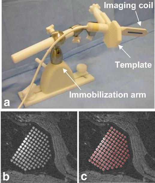
Needle placement and imaging device. a: The needle-guiding template is fixed at a right angle to the endorectal imaging coil. After positioning, both are fixed in place with an immobilization arm. b: The template holes, filled with surgical lubricant, are easily visualized in MR images. c: After registration of the position and orientation of the needle-guiding template, colored dots (representing the path of each needle hole) are projected through the image volume. Visualization of the template allows for easy verification of this registration.
A 3D-SSFP image volume was acquired (with slices approximately coplanar with the needle template face) to register the 3D position of the needle-guiding template relative to the MR image volume (TR = 4.4 ms, TE = 2.2 ms, FA = 56°, pixel BW = 560 Hz, FOV = 25 cm, slice thickness (ST) = 3 mm, 256 × 256, 60 slices, NEX = 1, scan time = 1:20). Prior to positioning, the holes in the needle template were filled with a water-soluble surgical lubricant (Surgilube, Fougera, Melville NY) that both eases catheter insertion and produces strong MR signal (T1 = 1850 msec and T2 = 240 msec, measured using FSE and SE pulse sequences, respectively). The regular pattern and spacing of the grid holes were easily recognized in the MR images (Fig. 1b). Using a custom-written image visualization and targeting program (running on a PC networked to the MR scanner), two points are selected to define an x-axis direction, two points to define a y-axis direction, and one point to define the origin of the needle template coordinate system (the middle hole at the exposed face of the template). While defining an origin, an x-axis direction, and a y-axis direction is sufficient to fully constrain the grid coordinate system, significant inaccuracies can be introduced because of angulation errors in the slice-select direction. Therefore, a 0.125“ diameter 6 cm long plastic tube was fixed to the anterior surface of the endorectal coil and filled with Surgilube such that it was MR-visible. Because the grid was rigidly fixed at a 90° angle relative to the endorectal coil, the path of the endorectal coil accurately defined the insertion axis of the template coordinate system (the x- and y-axis definitions were automatically updated such that they were normal to the insertion axis).
After the grid was fully registered, the trajectory of each needle hole was extended through the MR image space and superimposed on the image as a colored dot (i.e., each grid hole is projected along the insertion-axis of the template coordinate system). During the procedure, both the MR scanner and the PC running the image display and targeting program were controlled from within the scanner room, the former via an in-room display and mouse (Siemens Medical Systems) and the latter via a cordless mouse and keyboard (Cordless Elite Duo, Logitech, Fremont, CA). The targeting display was projected (LP340b LCD Projector, Infocus, Wilsonville, OR) onto a wall-mounted screen (Da-Mat, Da-Lite, Warsaw, IN) in the scanner room.
Clinical Procedures
After providing informed consent, patients were enrolled in an investigational protocol reviewed and approved by the NIH Clinical Center Institutional Review Board. All patients were being treated for intermediate to high risk localized prostate cancer at the Radiation Oncology Branch of the NCI, NIH Clinical Center. Each of the four patients underwent MRI-guided biopsy and conformal HDR brachytherapy boosts at the beginning and end of a 5-week course of conformal external beam radiation therapy.
HDR prostate brachytherapy uses an Iridium-192 source that is temporarily placed inside the prostate via hollow closed-tip catheters that are inserted through the perineum and into the prostate gland, commonly under ultrasound guidance (13). After parallel and equidistant placement of ∼14–18 catheters, a set of axial images is loaded into a brachytherapy dosimetry planning system and the location of the prostate, rectum, bladder, and urethra are defined. The system then optimizes the radiation dose to the prostate while minimizing the exposure of nearby normal tissues and produces a treatment prescription that defines the duration for which the radiation source should dwell at each axial position in each catheter (total radiation time is <20 min). This treatment, as performed under MRI guidance, is similar, with the exception that all planning and placement of catheters were performed within the MRI scanner.
All procedures were performed under general anesthesia. After registration of the perineal grid (as described previously), biopsy sites were selected, a grid hole and insertion depth for each site were read from the targeting application, the patient table was withdrawn from the scanner, and MR-compatible 14-gauge single-action beveled biopsy needles were inserted (MRI Devices, Waukesha WI). The patient was then advanced back into the scanner and, prior to tissue collection, FSE images were acquired to verify placement of the needles (TR = 741 ms, TE = 60 ms, ETL = 7, pixel BW = 125 Hz/pixel, FOV = 25 cm, ST = 4 mm, 256 × 256, 12 slices, NEX = 1, scan time = 0:28).
Following biopsy collection, needle insertion for HDR brachytherapy was performed. Generally, two to four 14-gauge, MR-compatible beveled or straight-tipped guiding needles (MRI Devices) were inserted at a time, after which FSE image volumes were acquired to confirm needle placement. Plastic brachytherapy catheters (5 Fr; Proguide, Nucletron, Columbia, MD) were then inserted through each guiding needle, which was subsequently removed. Catheter depths were chosen such that the entire superior–inferior dimension of the prostate was traversed without puncturing the bladder wall (which lies immediately superior to the prostate).
After placement of all brachytherapy catheters, a final set of T2-weighted images (in the axial, sagittal, and coronal image planes) were acquired (TR = 3500 ms, TE = 121 ms, ETL = 9, pixel BW = 130 Hz/pixel, FOV = 20 cm, ST = 3 mm, 256 × 256, 26 slices, NEX = 2, scan time = 3:38). The images were forwarded to a brachytherapy dosimetry planning system (PLATO, Nucletron) while the patient was transferred—without moving the needle template or the catheters—to a shielded room for radiation delivery. Currently, the procedure requires ∼2 hr for MR scanning and 5 hr for the entire treatment (from patient induction to the end of radiation treatment).
RESULTS
Needle Placement Accuracy
In a series of eight procedures in four patients, this system was used to perform a total of 32 targeted biopsy needle placements within the prostate. The mean biopsy needle placement error was 2.1 mm, 95% of the needle placement errors were less than 4.0 mm, and the maximum error measured was 4.4 mm (Fig. 2). Needle placement error is measured as the distance between the intended target site (i.e., the projection of the needle template hole) and the middle of the signal void created by the biopsy needle. As axial images were acquired and control of insertion depth is very accurate, only errors in the transverse plane were measured. Moreover, because biopsy cores are 1.0 cm long but only 1.5 mm in diameter, a transverse error in needle placement is much more significant than insertion depth error.
FIG. 2.
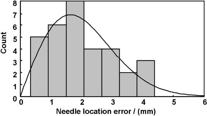
Needle placement accuracy histogram and maximum-likelihood Rayleigh distribution. Needle location errors (distance, measured in the axial plane, between the needle void and the intended target site) for the 32 biopsy needle placements. The mean placement error was 2.1 mm (error distribution is modeled by a Rayleigh distribution with a sigma value of 1.6 mm).
High-Dose-Rate Brachytherapy Catheter Placement
Following acquisition of four tissue samples in each patient, 14–15 HDR brachytherapy catheters were placed within the prostate. Total MR-time for placement of the catheters in the first two treatments was 2 hr; catheter placement required 1.5 hr in the subsequent six treatments. Figure 3 shows catheter placements for HDR brachytherapy treatments delivered before (Fig. 3a) and after (Fig. 3b) a 5-week course of external beam radiation therapy. Characteristic changes induced by radiation treatment (namely, atrophy of the normally bright peripheral zone of the prostate) are clearly visible in the second treatment. Figure 3c,d shows radiation isodose contours for each radiation treatment along with contours outlining the prostate, urethra, and the rectum. While the contour maps in Fig. 3 only show dose distribution in 2D, the treatment plan is generated and optimized in 3D using a full volume of MR data. A 3D measure of dose delivery to the prostate, V100 (percent of the target receiving ≥100% of the prescribed dose), was consistently greater than 90%, while a 3D measure of urethral overdose, urethral V125 (percent of the urethra receiving ≥125% of the dose) was <5%.
FIG. 3.
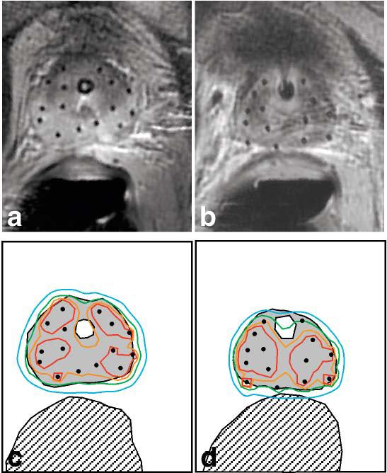
High-dose-rate (HDR) brachytherapy catheter placement and isodose maps. At the beginning (a) and end (b) of a 5-week course of external beam radiation therapy, HDR brachytherapy was performed using catheters placed under MRI guidance (both images are from the same patient). c,d: Radiation isodose maps, corresponding to a,b, indicate 150% (red contour), 125% (orange contour), 100% (green contour), and 75% (blue contour) of the prescribed radiation dose (1050 cGy). The prostate (gray filled region), urethra (white region inside the prostate), and rectum (hatched region) are also shown. Note that the green, 100% dose contour conforms well to the prostate margin, while overdose of the urethra and rectum is avoided.
DISCUSSION
Conventional MR imaging, MR spectroscopic imaging, dynamic contrast-enhanced MRI, and diffusion-weighted MRI have all shown great potential for the diagnosis and assessment of prostate cancer. However, there has been a significant barrier between the collection of these data and its application for targeted tissue acquisition and therapy. It has been widely assumed that the standard architecture of high-field MRI scanners precludes percutaneous access to the prostate. Therefore, most work has focused on the deformable registration of images acquired in high-field scanners (which contain valuable anatomical and functional data) with images acquired via ultrasound, CT, or low-field open MRI (which are more amenable to image-guided interventions). This deformable registration step from MRI to CT or ultrasound has been considered the sine qua non for these procedures (14). Here, we have shown that transperineal needle placement for brachytherapy and tissue biopsy can be effectively performed inside a standard 1.5 T MRI scanner with a 60-cm bore.
As this is a clinical procedure in which the patient is under general anesthesia, we placed great emphasis on choosing a very robust and simple registration technique. While point-based registration techniques have greater precedence in the literature and allow for assessment of registration accuracy (15), we found that unambiguous and rapid localization of single points (i.e., 3 mm diameter glass spheres filled with gadolinium solution) using MRI to be problematic and subject to frequent failure. Therefore, we chose a registration method that relies on more easily recognized patterns (e.g., the gel-filled perineal grid and the long gel-filled tube on the endorectal coil) to increase reliability. With this registration technique, the dominant source of needle placement error appears to be needle deflection within the tissue. In development studies using soft homogeneous gel phantoms (which do not cause appreciable needle deflection), needle placement errors were consistently under 2 mm. In addition, the distribution of needle placement errors (Fig. 2) is accurately modeled using a Rayleigh distribution, which assumes that error has an independent and identical normal distribution in the x- and y-dimensions with no directional bias. This is the expected error distribution if needle deflection, and not some systematic error source, was responsible for the observed errors.
The ability to perform needle placement in a standard MR scanner architecture has several important applications. Primarily, it will allow for the acquisition of tissue biopsies that are accurately colocalized with 1.5 T MR data. Thus, this method provides an ideal platform for the histologic validation of various MR imaging techniques. Prior methods have relied on correlations with tissue biopsy obtained under ultrasound guidance or with deformed whole gland specimens (16), both of which introduce significant localization errors. Second, because MRI provides excellent visualization of both the intra- and periprostatic anatomy, this technique will allow for serial acquisition of tissue from a specified site within the prostate. With techniques such as transrectal ultrasound guidance, it is much more difficult to obtain tissue consistently from the same site within the gland. Serial tissue acquisition will be crucial for the development of prostate cancer therapeutics (i.e., a tumor can be serially biopsied during the course of treatment to study the therapeutic agent's effect on the molecular and histological profile of the tissue) (17). Finally, this technique provides for direct planning and execution of a minimally invasive therapeutic procedure based on high-quality MR images. In previous work in animal models (in a standard 1.5 T scanner), we have demonstrated MRI guidance and monitoring while delivering solid and liquid therapeutic agents to the prostate (18).
In conclusion, a system for percutaneous needle access to the prostate inside a standard 1.5 T MRI scanner has been developed and applied in eight clinical procedures. Despite the relatively small bore size (60 cm) of the scanner, access to the perineum is possible by placing the patient in the left lateral decubitus position. Subsequent work will explore applications of this technique using dynamic contrast enhancement, MR spectroscopic imaging, and diffusion-weighted imaging.
ACKNOWLEDGMENTS
The authors thank Nucletron Inc., USA Instruments, and Siemens Medical for equipment and technical support; Dr. Robert J. Lederman for scanner resources; Frank Harrington for hardware development; Karen Ullman, Nancy Crouse, and Sharon Smith for nursing and therapy support; Victor Wright for imaging technical support; Dr. W. Kammerer for anesthesia; and Dr. Jean Pouliot (UCSF) for assistance with dosimetry software.
Grant sponsor: US Army; Grant number: PC 10029 Grant sponsors: NSF (Engineering Research Center PER grant), NIH training grant (to R.S.), ASTRO fellowship (to C.M.).
REFERENCES
- 1.Cancer facts & figures. 2003. American Cancer Society; Atlanta: 2003. [Google Scholar]
- 2.Chodak GW, Thisted RA, Gerber GS, Johansson JE, Adolfsson J, Jones GW, Chisholm GD, Moskovitz B, Livne PM, Warner J. Results of conservative management of clinically localized prostate cancer. N Engl J Med. 1994;330:242–248. doi: 10.1056/NEJM199401273300403. [DOI] [PubMed] [Google Scholar]
- 3.Potosky AL, Legler J, Albertsen PC, Stanford JL, Gilliland FD, Hamilton AS, Eley JW, Stephenson RA, Harlan LC. Health outcomes after prostatectomy or radiotherapy for prostate cancer: results from the Prostate Cancer Outcomes Study. J Natl Cancer Inst. 2000;92:1582–1592. doi: 10.1093/jnci/92.19.1582. [DOI] [PubMed] [Google Scholar]
- 4.Yu KK, Hricak H. Imaging prostate cancer. Radiol Clin North Am. 2000;38:59–85. doi: 10.1016/s0033-8389(05)70150-0. [DOI] [PubMed] [Google Scholar]
- 5.Kurhanewicz J, Swanson MG, Nelson SJ, Vigneron DB. Combined magnetic resonance imaging and spectroscopic imaging approach to molecular imaging of prostate cancer. J Magn Reson Imag. 2002;16:451–463. doi: 10.1002/jmri.10172. [DOI] [PMC free article] [PubMed] [Google Scholar]
- 6.D'Amico AV, Cormack R, Tempany CM, Kumar S, Topulos G, Kooy HM, Coleman CN. Real-time magnetic resonance image-guided interstitial brachytherapy in the treatment of select patients with clinically localized prostate cancer. Int J Radiat Oncol Biol Phys. 1998;42:507–515. doi: 10.1016/s0360-3016(98)00271-5. [DOI] [PubMed] [Google Scholar]
- 7.D'Amico AV, Tempany CM, Cormack R, Hata N, Jinzaki M, Tuncali K, Weinstein M, Richie JP. Transperineal magnetic resonance image guided prostate biopsy. J Urol. 2000;164:385–387. [PubMed] [Google Scholar]
- 8.Cormack RA, D'Amico AV, Hata N, Silverman S, Weinstein M, Tempany CM. Feasibility of transperineal prostate biopsy under interventional magnetic resonance guidance. Urology. 2000;56:663–664. doi: 10.1016/s0090-4295(00)00698-1. [DOI] [PubMed] [Google Scholar]
- 9.Fei B, Duerk JL, Boll DT, Lewin JS, Wilson DL. Slice-to-volume registration and its potential application to interventional MRI-guided radio-frequency thermal ablation of prostate cancer. IEEE Trans Med Imag. 2003;22:515–525. doi: 10.1109/TMI.2003.809078. [DOI] [PubMed] [Google Scholar]
- 10.Hata N, Jinzaki M, Kacher D, Cormak R, Gering D, Nabavi A, Silverman SG, D'Amico AV, Kikinis R, Jolesz FA, et al. MR imaging-guided prostate biopsy with surgical navigation software: device validation and feasibility. Radiology. 2001;220:263–268. doi: 10.1148/radiology.220.1.r01jl44263. [DOI] [PubMed] [Google Scholar]
- 11.Kaplan I, Oldenburg NE, Meskell P, Blake M, Church P, Holupka EJ. Real time MRI-ultrasound image guided stereotactic prostate biopsy. Magn Reson Imag. 2002;20:295–299. doi: 10.1016/s0730-725x(02)00490-3. [DOI] [PubMed] [Google Scholar]
- 12.DiBiase SJ, Hosseinzadeh K, Gullapalli RP, Jacobs SC, Naslund MJ, Sklar GN, Alexander RB, Yu C. Magnetic resonance spectroscopic imaging-guided brachytherapy for localized prostate cancer. Int J Radiat Oncol Biol Phys. 2002;52:429–438. doi: 10.1016/s0360-3016(01)02609-8. [DOI] [PubMed] [Google Scholar]
- 13.Martinez AA, Gustafson G, Gonzalez J, Armour E, Mitchell C, Edmundson G, Spencer W, Stromberg J, Huang R, Vicini F. Dose escalation using conformal high-dose-rate brachytherapy improves outcome in unfavorable prostate cancer. Int J Radiat Oncol Biol Phys. 2002;53:316–327. doi: 10.1016/s0360-3016(02)02733-5. [DOI] [PubMed] [Google Scholar]
- 14.Mizowaki T, Cohen GN, Fung AY, Zaider M. Towards integrating functional imaging in the treatment of prostate cancer with radiation: the registration of the MR spectroscopy imaging to ultrasound/CT images and its implementation in treatment planning. Int J Radiat Oncol Biol Phys. 2002;54:1558–1564. doi: 10.1016/s0360-3016(02)03805-1. [DOI] [PubMed] [Google Scholar]
- 15.Fitzpatrick JM, West JB, Maurer CR., Jr Predicting error in rigid-body point-based registration. IEEE Trans Med Imag. 1998;17:694–702. doi: 10.1109/42.736021. [DOI] [PubMed] [Google Scholar]
- 16.Wefer AE, Hricak H, Vigneron DB, Coakley FV, Lu Y, Wefer J, Mueller-Lisse U, Carroll PR, Kurhanewicz J. Sextant localization of prostate cancer: comparison of sextant biopsy, magnetic resonance imaging and magnetic resonance spectroscopic imaging with step section histology. J Urol. 2000;164:400–404. [PubMed] [Google Scholar]
- 17.Crawford ED, Fair WR, Kelloff GJ, Lieber MM, Miller GJ, Scardino PT, DeAntoni EP. Chemoprevention of prostate cancer: guidelines for possible intervention strategies. J Cell Biochem Suppl. 1992;16H:140–145. doi: 10.1002/jcb.240501232. [DOI] [PubMed] [Google Scholar]
- 18.Susil RC, Krieger A, Derbyshire JA, Tanacs A, Whitcomb LL, Fichtinger G, Atalar E. A system for MRI guided prostate interventions — a canine study. Radiology. 2003;228:886–894. doi: 10.1148/radiol.2283020911. [DOI] [PMC free article] [PubMed] [Google Scholar]