Abstract
With the advent of breath-hold MR cardiac imaging techniques, the minimization of TR and TE for oblique planes has become a critical issue. The slew rates and maximum currents of gradient amplifiers limit the minimum possible TR and TE by adding dead-periods to the pulse sequences. We propose a method of designing gradient waveforms that will be applied to the amplifiers instead of the slice, readout, and phase encoding waveforms. Because this method ensures that the gradient amplifiers will always switch at their maximum slew rate, it results in the minimum possible dead-period for given imaging parameters and scan plane position. A GRASS pulse sequence has been designed and ultra-short TR and TE values have been obtained with standard gradient amplifiers and coils. For some oblique slices, we have achieved shorter TR and TE values than those for nonoblique slices.
Keywords: oblique MRI, pulse design, ultra-fast MRI, cardiac MRI
INTRODUCTION
In segmented k-space data acquisition, to be able to freeze cardiac motion and acquire CINE images in a single breath-hold, TR should be in the range of 7 ms (1, 2). Shorter TR values correspond to shorter breath-hold periods or more CINE frames.
In this paper, we will describe a method to achieve the minimum TE and TR values for imaging oblique planes by minimizing dead-periods. We define dead-periods in a pulse sequence as the time intervals when neither RF pulses are applied nor data are acquired. A GRASS pulse sequence has two dead-periods: between the RF pulse and the readout period, and between readout and the next RF pulse. These segments are labeled as D1 and D2 on Fig. 1a. Without changing the slice profile or increasing the receiver bandwidth, minimization of TR and TE is possible by reducing the dead-periods.
FIG. 1.
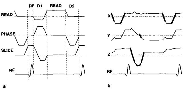
(a) A GRASS pulse sequence optimized for imaging nonoblique planes. Maximum slew rates and maximum gradient amplitudes are used. The segments, RF, D1 (dead-period l), READ, and D2 (dead-period 2) are shown on the graph. (b) The waveforms applied to the gradient amplifiers when the imaging plane is assumed to be obtained by 30, 30, and 45 degree rotations around the x, y′, and z″ axes, respectively. The segments of the waveform that exceed the maximum allowed gradient level and slew rate are designated by bold lines.
It has recently been shown that minimizing dead-periods will not cause any reduction in SNR for spoiled GRASS pulse sequences, and it will cause an increase in SNR for GRASS pulse sequences (3, 4). Therefore, in fast imaging pulse sequences, minimizing dead-periods increases the image quality and/or decreases data acquisition time with no penalty.
The maximum amplifier current that an amplifier can drive limits the gradient level, and the maximum amplifier voltage limits the slew rate. These hardware constrains determine the minimum possible dead-period.
For imaging of nonoblique planes, trapezoidal waveforms with maximum slew rate ramps are known to be optimal for covering a certain area with a gradient waveform in the shortest possible time. A GRASS pulse sequence can be optimized for nonoblique planes using trapezoidal waveforms in the dead-periods as shown in Fig. 1a.
However, if these waveforms are used for imaging oblique planes, the maximum slew rate and gradient level limitations may be violated because the waveforms shown in Fig. 1a will no longer be applied to the gradient amplifier. Instead, the waveforms in Fig. 1b may be applied depending on the orientation of the slice. The waveforms that will be applied to the amplifiers are actually the weighted sum of the slice, readout, and phase encoding waveforms where the weights are determined by slice orientation. The portions of the waveforms that exceed the limitations are shown with bold lines in Fig. 1b. If these waveforms are applied to the amplifier, the gradients will not be able to produce the waveforms, and image artifacts and distortions will result.
There are three ways to solve this problem. The most conservative method is not to apply two or more gradient waveforms simultaneously (5). The second method is to decrease the slew rates and the maximum allowed gradient levels in the designed trapezoidal waveforms by a factor of . This method is also conservative, and it causes an unnecessary increase in the minimum possible TE and TR. The third method also uses trapezoidal waveforms. The slew rates and the maximum gradient levels are calculated depending on the orientation of the slice and the number of active gradients (6). We call this method “scan plane optimization.” Very short TR and TE values can be achieved using this method. If all the gradients are active, as in the dead-periods of the GRASS pulse sequence, the slew rate and maximum gradient level reduction factor ranges from 1 to .
It is always possible to decrease TR and TE using gradient amplifiers and coils that allow higher gradient levels and higher slew-rates. But it would be more cost-effective to use existing hardware more efficiently.
In this paper we propose a new algorithm for calculating the minimum duration dead-periods for scanning a given oblique plane. In this algorithm, the requirements of the gradient pulses in the scan plane during a dead-period are parameterized with three values: the starting amplitude, the ending amplitude, and the area. These values are transformed from the scan plane coordinates to the amplifier coordinates with the appropriate rotation operator. In the amplifier coordinates the shortest duration pulse for each gradient amplifier for a given starting amplitude, ending amplitude, and area can be achieved with a maximum slew rate trapezoid. We call this waveform a “hardware optimized trapezoid” (HOT). For some pulse sequences, such as those with velocity encoding and flow compensation, a knowledge of moments is required. We will not consider these special sequences in the minimization algorithm.
The following section describes the algorithm and provides a design example.
ALGORITHM
The three parameters of a dead-period (the starting and ending gradient amplitudes and the area) can be calculated based on particular pulse sequence requirements. For example, in a GRASS pulse sequence, the slice gradient in D1 (dead-period 1) should start with its value during the RF period and end with zero. In this period, the area under the gradient waveform should cancel half the area covered during the RF period. The starting and ending gradients and the required area for the phase encoding and readout waveforms can be determined in a similar manner (Fig. 2a).
FIG. 2.
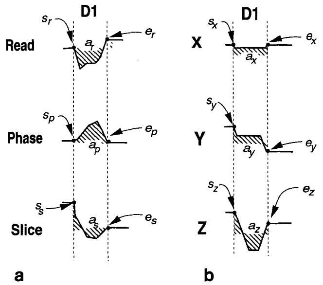
(a) The starting gradient values, s, the ending gradient values, e, and the areas, a, for slice, readout, and phase encoding directions. The subscripts r, p, and s represent the readout, phase encoding, and slice directions, respectively. The waveform shapes in D1 (the dead-period 1) are arbitrary. (b) The starting and ending gradient values and the areas for amplifier current directions. These parameters are calculated using Eq. [l]. The subscripts x, y, and z represent the amplifier directions. Trapezoidal waveforms with maximum slew rates are designed using the three parameters in each direction.
The waveform design limitations are the slew rate and maximum current that an amplifier can achieve. The major problem in the design of gradient waveforms in a dead-period is that the limitations are defined in the amplifier current coordinates but the imaging parameters are defined in the slice, readout, and phase encoding directions. A transformation from one coordinate system to another is required.
Any oblique prescription can be defined by a 3 × 3 orthogonal rotation matrix that translates from the slice, readout, and phase encoding waveforms to the physical gradient amplifier coordinates. The transformation of the three imaging parameters to the amplifier current coordinates can be achieved by multiplication of the parameter vectors with this rotation matrix, R, as follows:
| [1] |
where s and e represent the starting and ending gradient values and a represents the area to be covered. The subscripts r, p, and s represent the readout, phase encoding, and slice directions, and x, y, and z represent the amplifier current directions. In this way, for each amplifier current direction, the three parameters of starting and ending gradient values and area can be calculated.
The waveform of shortest duration that satisfies these parameters is called the “hardware optimized trapezoid” (HOT) and it is a trapezoidal or triangular waveform with maximum slew rate ramps. The equation for the area covered by a HOT waveform with arbitrary starting and ending levels is a first or second order equation. It is possible to evaluate the minimum time that is necessary for an amplifier to cover a certain area using HOT pulses by solving the related equation (Fig. 2b). The remaining problem is to keep the dead-period the same for each amplifier and for each phase encoding step. It is possible to reduce the calculation time for the global minimum dead-period by considering only the maximum and the minimum phase encoding steps. Because the required area for each amplifier is a linear function of the phase encoding step, either the maximum or the minimum phase encoding step will give the longest of the minimum dead-periods.
Once a global minimum for each dead-period is determined, a HOT pulse that satisfies the three parameters (the starting and ending current values and the area) and fits into this minimum time can be designed. An outline of the algorithm is shown with pseudo-code in Fig. 3.
FIG. 3.
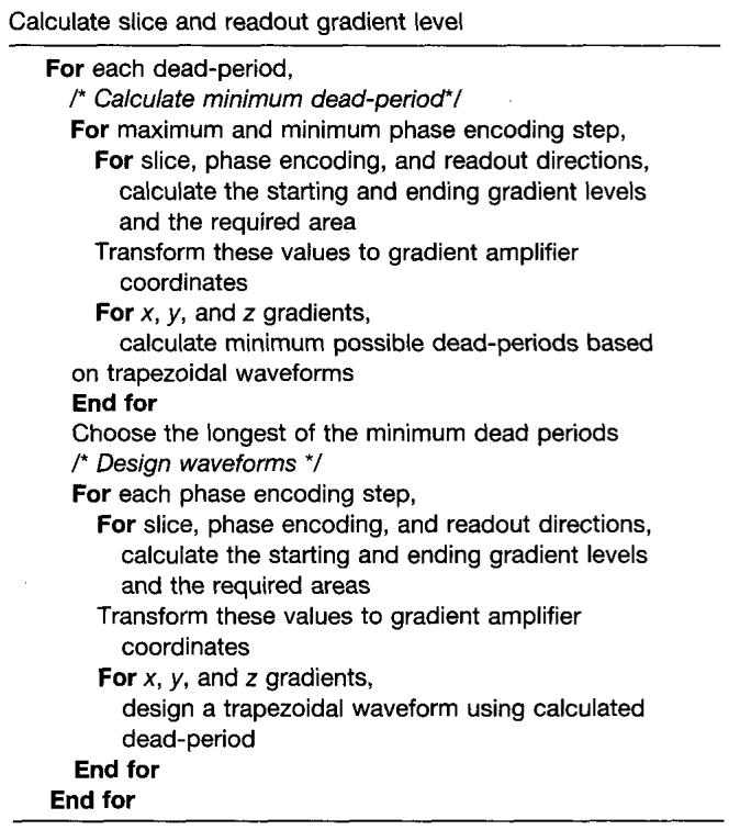
An outline of the pulse design algorithm for oblique scans.
Another important point is that to achieve ultra-short TR and TE values, high duty cycle gradient amplifiers are required. To decrease power consumption, whenever possible the gradient level is decreased and the duration of the HOT pulse is increased. Because the waveforms that will be applied to amplifiers are designed, the power required from the amplifiers can be evaluated by integrating the square of the waveform over time and TR can be increased if necessary.
A sample design is shown in Fig. 4a. As in Fig. 1, the oblique matrix is assumed to be obtained by 30, 30, and 45 degree rotations around the x, y, and z axes. This sequence can be directly applied to the gradient amplifiers or may be transformed back to the slice, readout, and phase encoding coordinate system by multiplying the gradient waveform vector by the inverse of the oblique rotation matrix. The waveform after this transformation is shown in Fig. 4b.
FIG. 4.
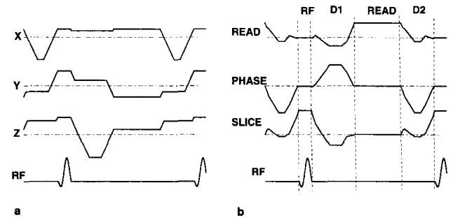
(a) The hardware optimized trapezoids for the GRASS pulse sequence. These waveforms show the amplifier currents. (b) Optimized GRASS pulse sequence obtained by transforming the amplifier currents back to the slice, readout, and phase encoding directions. In this waveform, the imaging plane is assumed to be obtained by 30, 30, and 45 degree rotations around the x, y′, and z″ axes, respectively, as in Fig. 1.
It is interesting that although the waveforms applied to the amplifiers are simple trapezoids, the slice, readout, and phase encoding waveforms are complicated. In conventional designs this fact is reversed, i.e., the slice, readout, and phase encoding waveforms are simple but the waveforms that are applied to the gradient amplifiers are complex (Fig. 1).
RESULTS
Using HOT pulses, we have achieved TR values in the range of 7 ms on oblique planes for a GE Signa version 5.2 scanner that has isotropic gradients with a maximum gradient of 1 Gauss/cm, and a slew rate of 0.167 T/s/cm. The minimum possible TR with this pulse sequence depends on the angle of the oblique plane and specific imaging parameters such as slice thickness, FOV, receiver bandwidth, and number of phase encoding steps. A short axis image of the heart with a double oblique view was acquired using segmented k-space cardiac tagging (2) with the following imaging parameters: 5 mm slice thickness; 250 Hz/pixel receiver bandwith; 360 mm FOV, matrix size 256 × 128; partial echo and partial excitation, i.e., one sinc side lobe before and no side lobe after the main lobe of the sinc RF pulse. The image is shown in Fig. 5.
FIG. 5.
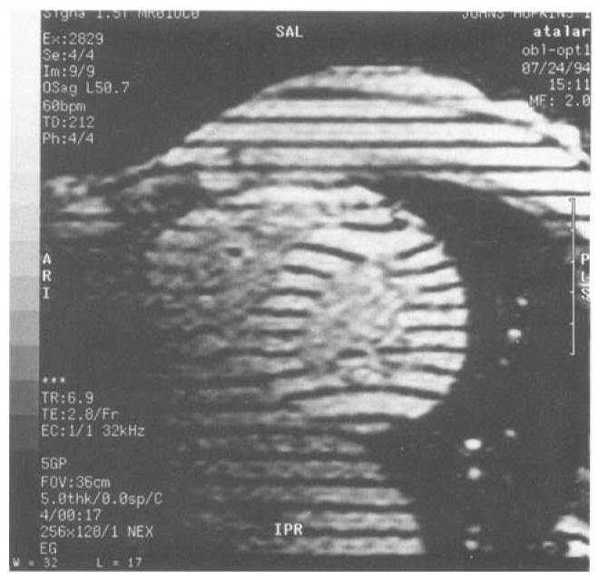
A short axis image of the heart with a double oblique scan plane. The image was acquired with minimum TR and TE for this plane using HOT pulses.
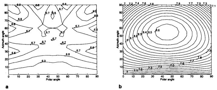
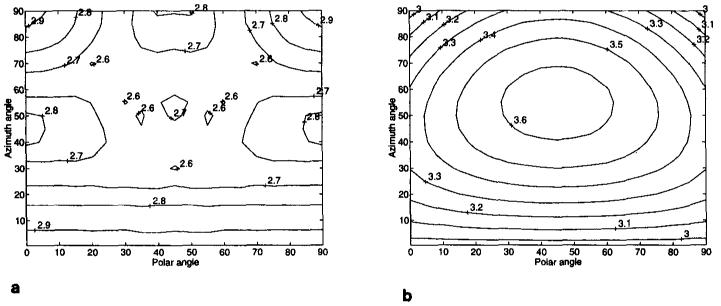
To evaluate the effect of the HOT pulses, we calculated the minimum TR and TE for the imaging parameters given above. Minimum TR and TE values were calculated for all possible oblique orientations and phase and frequency encoding directions with a resolution of 5 degrees. The results are summarized in Table 1. In addition, TR and TE were also calculated with the scan plane optimization method. The results are also shown in Table 1. Reduction in TR and TE of up to 30% and 40% have been obtained, respectively. TR and TE as a function of slice orientation are shown on contour plots in Fig. 6 and 7. In these figures, plane orientation is given by the azimuth and polar angles of the plane normal. For these plots, the frequency and phase directions and the RF pulse width that gave the minimum TR were used.
Table 1.
Statistics of TR and TE for 2888 Scan Plane Orientation for Comparison of the Dead-Time Minimization Algorithms
| Hot pulses |
Scan plane optimization |
|
|---|---|---|
| TR | ||
| Min | 6.516 | 6.964 |
| Max | 6.964 | 8.664 |
| Mean | 6.769 | 7.945 |
| SD | 0.112 | 0.463 |
| TE | ||
| Min | 2.588 | 2.952 |
| Max | 2.952 | 3.648 |
| Mean | 2.744 | 3.355 |
| SD | 0.101 | 0.189 |
FIG. 6.
TR variation as a function of plane orientation for (a) the HOT pulses and (b) scan plane optimization. The vertical axis is the azimuth angle (the angle between the scan plane normal and the z-axis). The horizontal axis is the polar angle (the angle between the scan plane normal and x-axis on the xy plane).
FIG. 7.
TE variation as a function of plane orientation for (a) the HOT pulses and (b) scan plane optimization. The vertical axis is the azimuth angle (the angle between the scan plane normal and the z-axis). The horizontal axis is the polar angle (the angle between the scan plane normal and x-axis on the xy plane).
As can be observed, the TR variation with HOT pulses as a function of slice position is less than the TR variation for the scan plane optimization method. With HOT pulses, the TR becomes smaller as the position of the slice becomes oblique. Conversely, scan plane optimization causes an increase in TR as the slice becomes oblique. The same behavior for TR can be observed for TE, i.e., with HOT pulses, the highest TE value was observed for the nonoblique planes whereas in the scan plane optimization method the lowest TE was observed at the nonoblique planes. For nonoblique, HOT pulses give the same minimum TR and TE as that obtained with scan plane optimization. It is important to note that this behavior is specific for the given imaging parameters. HOT pulses do not guarantee that the maximum TR and TE will occur at the nonoblique planes.
CONCLUSION
We have developed an optimum method for minimizing dead-periods in imaging oblique slices. With this technique, the waveforms that are applied to the gradient amplifiers are designed rather than designing the slice, phase encoding, and readout waveforms.
Using this technique, it is possible to obtain the minimum TR and TE values achievable for a set of gradient coils and amplifiers. The TR and TE variation as a function of slice position are minimal. Also, a reduction of up to 30% in TR can be achieved compared with the previous dead-time minimization methods for the parameters typically used in clinical MR imaging.
This waveform optimization method is applicable not only to the minimization of dead-periods of a GRASS sequence but also to the segments of any MR pulse sequence where the shape of the waveform is not important. We believe that this method will have an important impact on oblique echo planar imaging where minimization of dead-periods is critical.
The HOT pulses are applicable to nonisotropic gradients. No modification of the algorithm is necessary. While designing the waveform for each amplifier, the specifications of that particular amplifier should be used.
The most important drawback of the HOT pulses is that there are different waveforms for each phase encoding step. Because of this, it requires more waveform memory and CPU time than the scan plane optimization method.
This algorithm has been implemented on a GE Signa 5.2 clinical scanner and runs without any noticeable delay. We are also developing an optimum pulse design method for imaging oblique planes with flow-compensated or velocity-encoded waveforms (7).
REFERENCES
- 1.Atkinson DJ, Edelman RR. Cineangiography of the heart in a single breath hold with a segmented turboFLASH sequence. Radiology. 1991;178:357–360. doi: 10.1148/radiology.178.2.1987592. [DOI] [PubMed] [Google Scholar]
- 2.McVeigh ER, Atalar E. Cardiac tagging with breath hold CINE MRI. Magn. Reson. Med. 1992;28:318–327. doi: 10.1002/mrm.1910280214. [DOI] [PMC free article] [PubMed] [Google Scholar]
- 3.Reeder SB, McVeigh ER. Effect of high-speed gradients on snr in ultra-fast gradient echo imaging. J. Magn. Reson. Imaging. 1994;4(P):37. doi: 10.1002/mrm.1910320510. [DOI] [PMC free article] [PubMed] [Google Scholar]
- 4.Reeder SB, McVeigh ER. The effect of high performance gradients on fast gradient echo imaging. Magn. Reson. Med. 1994;32:612–621. doi: 10.1002/mrm.1910320510. [DOI] [PMC free article] [PubMed] [Google Scholar]
- 5.Bernstein MA, Perman WH, Besozzi MC, Thomasson DM. Pulse sequence generated oblique magnetic resonance imaging: application to cardiac imaging. Med. Phys. 1986;13:648–657. doi: 10.1118/1.595868. Erratum: Med. Phys.14(1), 145 (1987). [DOI] [PubMed] [Google Scholar]
- 6.Bernstein MA, Licato PE. Angle-dependent utilization of gradient hardware for oblique MRI. J. Magn. Reson. Imaging. 1994;4:105–108. doi: 10.1002/jmri.1880040121. [DOI] [PubMed] [Google Scholar]
- 7.Atalar E, McVeigh ER. Minimization of TE for velocity-encoded or flow compensated pulse sequences in imaging oblique planes; Proc., SMR, 2nd Annual Meeting; San Francisco. 1994. p. S23. [Google Scholar]


