1. Introduction
1.1. Synthesis is reaction and separation
The enterprise of organic synthesis is a collective endeavor involving reaction and separation followed by identification and analysis.1 The “reaction and separation stage” produces a new organic molecule while the “identification and analysis stage” proves what the molecule is and how pure it is. The yield of every organic reaction depends on both the efficiency of the underlying reaction and the ability to recover the target product in pure form from the reaction mixture. Reaction methods have evolved and improved dramatically over the past decades and continue to do so. On the other hand, while they continued to be refined, the core separation methods that synthetic chemists routinely use have not change for a decade or more.
The concept of the “ideal reaction” serves as an inspiring, if unattainable, goal for basic research in synthesis.2 In the trenches (the labs), reactions are usually a means to an end (chemical and drug discovery), and chemists tend to spend more time searching, hoping and wishing for the “ideal separation”1a,b. It is rare not every day that a new, generally applicable separation method comes along.
The purpose of this Report is to provide an overview of the increasingly popular new separation technique of fluorous solid-phase extraction (F-SPE). Though it is still less than a decade old,3 the technique has matured rapidly and is now ready for prime time, as illustrated by the expanding uses over the last 2–3 years.4 After a brief introduction of two varieties of F-SPE—standard and reverse—we provide comprehensive tabular collections of published uses in small molecule synthesis that are intended to illustrate both the scope of the method and the diverse array of reagents and materials that are now available. We close by providing interested readers with practical information on how to conduct an F-SPE.
1.2. Light fluorous chemistry
The bifurcation of fluorous chemistry into “heavy” and “light” branches in 1999 was a direct result of the introduction of F-SPE. The earliest work in the fluorous field focused on introducing large (therefore “heavy”) fluorous tags onto organic and oganometallic reaction components (catalysts, reagents, reactants, etc.).5,6 These tags then rendered the resulting tagged reaction components soluble in fluorocarbon and other highly fluorinated solvents, and enabled powerful techniques like fluorous biphasic and triphasic reactions, biphasic and triphasic liquid-liquid extractions (LLEs),7 thermomorphic reactions, and more.8 The exciting branch of heavy fluorous chemistry, whose techniques are especially suitable for large scale processes, continues to forge ahead at a rapid pace today.
Heavy fluorous tags are often called ponytails because they usually sprout several fluoroalkyl chains bearing 39 or more (often many more) fluorines. From the outset, workers in the field were bent on giving these ponytails a haircut. The resulting light fluorous molecules (typically with 9–17 fluorines) are cheaper and more readily available, and are much more soluble in common organic solvents. But therein lies the rub—they are also much less soluble in fluorous solvents so the LLE breaks down. The enabling advance for light fluorous molecules was the replacement of the LLE with an SPE.3,9,10
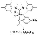
Figure 1 compares and contrasts a pair of related heavy and light fluorous alkene metathesis11 catalysts. The heavy fluorous catalyst 1 is a copolymer of a catalyst component and the fluorous acrylate12 (However, many molecular heavy fluorous catalysts are also know). It is freely soluble in FC-72 but is insoluble in organic solvents like CH2Cl2 and EtOAc. Following a reaction with a substrate in C6H5CF3/CH2Cl2 the catalyst is extracted away from the products with FC-72. Multiple cycles of recovery and reuse were conducted. In principle, it makes little difference that heavy catalysts like 1 have low or even no solubility in the organic reaction solvent, so long as the reaction works. In practice, however, it makes a big difference, especially in small scale discovery chemistry. Target reactions may fail either because they are too slow to occur at all or because other side reactions occur more rapidly. The rate of a target reaction often depends directly on the concentration of a reactant in the reaction solution—in other words, on its solubility. So having soluble reaction components is a huge advantage, especially when reactions are not understood in great detail, as is always the case with new reactions.
Figure 1.
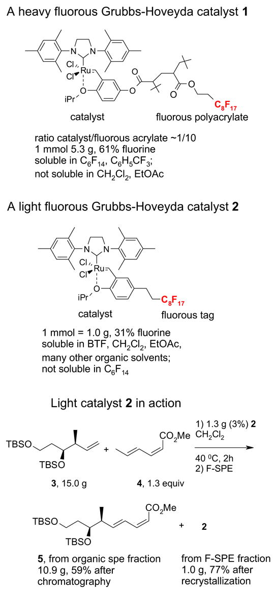
Comparing and contrasting light and heavy fluorous Grubbs-Hoveyda
Light fluorous catalyst 2 has very different physical properties from heavy cousin 1.13 A green crystalline solid, it is freely soluble in most common organic reaction solvents but has low solubility in fluorous solvents like FC-72. These properties are advantageous for running reactions since one can simply use the standard conditions for non-fluorous reagents without modification.
For example, cross metathesis of 3 and 4 has been conducted at University of Pittsburgh on large scale for a preparative total synthesis of analogs of the anti-cancer agent dictyostatin.14 In a typical run, 15 g of alkene 3 and diene 4 (1.3 equiv) were combined with 1.3 g of catalyst 2 (3%) in 50 mL of dichloromethane. The homogeneous mixture was warmed to 40 °C for 2 h and cooled prior to evaporation of the reaction solvent. The mixture was then subjected to F-SPE over 50 g of fluorous silica gel to provide an organic fraction of cross- and self-metathesis products. Purification of this fraction provided the cross-coupled product 5 in 60% yield. The fluorous fraction was primarily the recovered catalyst 2 and could be used as such; however, we prefer to recrystallize this product to ensure high catalyst quality for the next use in either the same or a different reaction. Recrystallization of the crude fluorous product from this reaction provided 1.0 g (77%) of recovered catalyst, which was of comparable appearance and purity to the original sample.
Comparing and contrasting this type of light fluorous reaction with traditional solution phase methods and also solid phase methods highlights the advantages of the fluorous approach.15 In reaction, identification and analysis phases, the light fluorous approach resembles traditional solution phase methods rather than solid phase methods because the fluorous reaction components are molecules, not materials. Light fluorous molecules are often soluble in a broad range of standard organic reaction solvents and exhibit reactivity comparable to their non-fluorous parents.16 In other words, their reaction features are readily predicted. Fluorous molecules can be routinely analyzed by all standard spectroscopic methods and separated by both fluorous and non-fluorous techniques.
The advantage over traditional solution phase chemistry comes at the separation stage, because the separation of fluorous compounds by F-SPE is a reliable and generic procedure that resembles more a filtration than a chromatography. The separation depends primarily on the presence or absence of a fluorous tag, not polarity or other molecular features that control traditional chromatography. In many respects, light fluorous methods capture the best features of traditional solution-phase chemistry, yet still provide a facilitated separation.
2. Concept of F-SPE
2.1. Classification of F-SPE
F-SPE separations can be grouped into two main classes: standard and reverse. The standard or original solid phase extraction is much more common and involves the partitioning between a fluorous solid phase and a fluorophobic liquid phase.4 This technique has been used in many settings (manual SPE, automated SPE, plate-to-plate SPE, automated flash chromatography, HPLC) and has proven generality. In contrast, the nascent technique of reverse fluorous solid phase extraction17 uses a fluorophobic solid phase and a fluorous liquid phase. While there are currently only a few examples, the reverse F-SPE technique has considerable potential. Both techniques have been described in detail4,17 and we provide here a brief summary. Section 5 of the Report on practical aspects is for those planning to use the standard F-SPE technique in the lab.
SPE18 and chromatography are related because both involve partitioning between solid and liquid phases, and the transition zone between the two techniques is grey. In chemical analysis, an SPE is usually used to help concentrate a very dilute sample; however, in synthesis it is used to partition a concentrated sample rapidly into two fractions. In general, the synthetic SPE resembles a filtration more than a chromatography, and has higher loading levels and lower solvent volumes. After elution of a first fraction with a first solvent, a second solvent of stronger eluting power is added to elute a second fraction. That second fraction is simply too well adsorbed on the solid phase to be eluted by the first solvent in a practical time frame. Multiple fraction collection and analysis are not required—there is one wash for unretained molecules and one wash for retained molecules. In chromatography, elution of successive fractions is typically a “time-dependent” process—sooner or later, all of the fractions elute. In SPE, elution of successive fractions is a “solvent-dependent” process.
Among different packing materials for SPE, ion-exchange resins have good retention selectivity, give “mass-controlled” separation, and are little affected by the volume of the loading solvent. In contrast, polarity-based normal- and reverse-phase silica gels are much less selective and are more sensitive to the polarity and volume of the loading solvent.18 Fluorous silica gel has strong and selective fluorine-fluorine interaction with fluorous molecules.
2.2. Standard F-SPE
Standard F-SPE was introduced in 19973 and involves the use of a fluorous solid phase and a fluorophilic (but not fluorous) solvent, as illustrated in Figure 2. The fluorous solid phase is typically silica gel with a fluorocarbon bonded phase (-SiMe2(CH2)2C8F17), and this is commercially available from Fluorous Technologies, Inc. under the trade name of FluoroFlash®.19
Figure 2. A cartoon of a “standard” F-SPE.
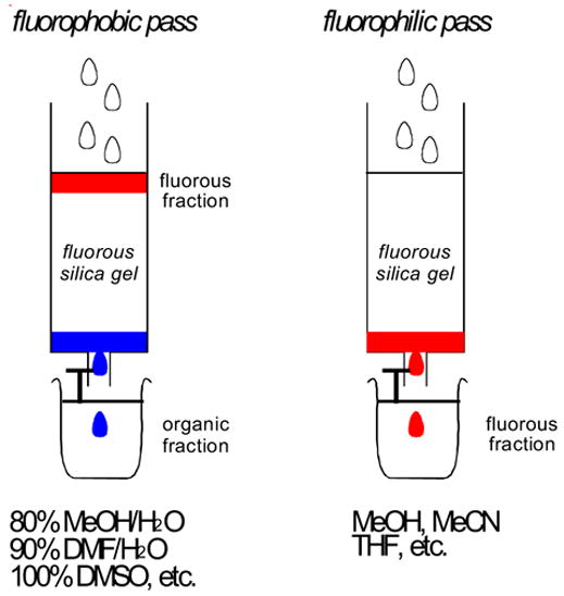
The organic fraction is blue and the fluorous fraction is red

Briefly, a crude reaction mixture containing both fluorous and non-fluorous reaction components is charged onto fluorous silica gel and then the silica is eluted with a fluorophobic solvent like 70–80% MeOH/H2O, 50–60% CH3CN/H2O, 80–90% DMF/H2O, or 100% DMSO. In this “fluorophobic pass”, non-fluorous (organic) compounds typically move at or near the solvent front and elute immediately, while fluorous compounds are retained on the silica gel. In the ensuing “fluorophilic pass”, elution with one of many organic solvents (water-free MeOH or CH3CN, THF, among others) then provides a fluorous fraction containing those compounds bearing the fluorous tag.
The procedure is simple, general and reliable, and has now been used many times in diverse settings. Importantly, it does not seem to be very sensitive to the polarity of either the fluorous component or the organic component. Thus, the standard F-SPE is a very attractive separation technique in library settings since products with very different characteristics will all exhibit substantially the same behavior.
2.3. Reverse F-SPE
Reverse F-SPE is a new technique with few examples to date,17 but with considerable potential. The philicities of the solid phase and liquid phase are reversed, and standard silica gel is used as the polar solid phase while blends of fluorous20 and organic solvents as the fluorophilic liquid phase. The concept is illustrated in Figure 3. A sample containing fluorous and non-fluorous components is charged to regular silica gel with standard solvents, and then the silica is eluted with a fluorophilic solvent to remove a fluorous fraction (fluorophilic pass). In our first paper,17 we used FC-72 (perfluorohexanes) and ether, among other combinations, but we now more often use HFE-7100 (perfluorobutyl methyl ether) blended with ethyl acetate, ether or another organic cosolvent. Following that, a fluorophobic pass can be conducted with any standard organic solvent.
Figure 3. A cartoon of a “reverse” F-SPE.
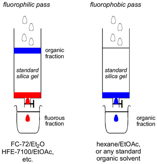
The organic fraction is blue and the fluorous fraction is red
Perfluoroalkyl alkyl ethers like HFE-7100 are preferred over fluorocarbons because the fluorocarbons have very poor eluting power (even for most light fluorous compounds) and they have limited miscibility in organic solvents. Because of this, the range of fluorophilic blends with such solvents is limited.
The reverse F-SPE is attractive for removing fluorous reagents, catalysts and other byproducts from standard organic target products because after the fluorophilic pass is complete, the organic product absorbed on the head of the silica column can simply be purified by standard flash chromatography. It is also attractive because solvent elution conditions and prospects for success can be readily assessed by using standard silica gel TLC plates.
However, because standard silica gel is used, the behavior of reverse fluorous methods can be significantly affected by the polarity of both the fluorous and the non-fluorous components. While we still have limited experience, we currently feel that reverse F-SPE exhibits the most power when used to separate relatively non-polar fluorous components from relatively polar organic components. Of course, such kinds of separations might also be conducted by standard chromatography with traditional solvents like hexane/EtOAc. However, the replacement of non-polar solvent (hexane) of this combination with a fluorous solvent will often provide a better separation because this will significantly retard the elution of the organic fraction without retarding nearly as much (and perhaps even promoting) the elution of the fluorous component.
3. F-SPE Methods
3.1. Pressure and gravity F-SPE
Depending on the type of fluorous silica gel that is used, F-SPEs can be driven with light pressure (positive or negative) or by gravity. Commercially available FluoroFlash® SPE silica gel21 has 40–60 μm particle sizes. Cartridges packed with this size silica gel require positive pressure on the top or negative pressure under the bottom to drive the elution process. When particle size is increased to around 120 μm, gravity SPE is possible.22
3.2. Common F-SPE systems
A basic unit for conducting 1–24 SPEs shown in Figure 4 is commercially available from Supelco. Other companies such as Fisher and Waters sell comparable units. The unit is a 2 × 12 manifold and employs negative pressure, which is convenient for SPE cartridges with 2–10 g silica gel. Fractions are collected in a 10–15 mL test tube. For F-SPE with big cartridges (6–10 g silica gel), more than one tube is needed to collect both non-fluorous and fluorous fractions.
Figure 4.
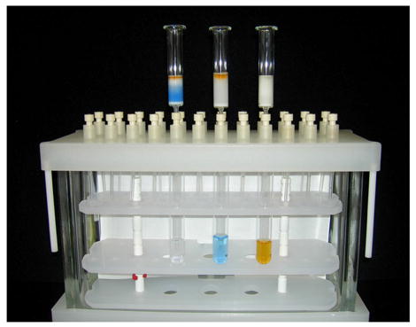
2 × 12 Vacuum SPE manifold
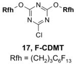
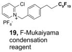
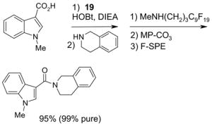
Since the F-SPE process is highly reproducible and functional group independent, it can be easily automated or used in a plate-to-plate format. For parallel synthesis, plate-to-plate F-SPE can significantly increase the throughput. Samples are loaded onto a plate whose cartridges are packed with fluorous silica gel and fractions are collected in a matched receiving plate. The silica gel plate may be cartridge- or well-formated. Figure 5 shows a 24-cartridge plate and a 24-well plate of VacMaster® form Biotage.23 Similar systems are also available from United Chemical Technologies, Supelco, and Waters. If 50 μm fluorous silica gel is used, then the receiving plate is connected to a vacuum pump. The 24-channel plate has the following technical features: 1) each cartridge has 6 mL, and each well has 10 mL volume, which can be charged with 3–4 g of fluorous silica gel leaving ~3–5 mL top space for elution solvent; 2) each receiving well has 10 mL volume for collecting fraction; 3) a six-channel pipette is used for parallel sample loading and solvent loading; and 4) the Whatman® receiving plate24a has a standard footprint which can be directly concentrated in a Genevac vacuum centrifuge. The 24-well plate is good for parallel purification of 10–100 mg quantity of products. This system has been demonstrated in the purification of small libraries produced involving amine scavenging reactions with fluorous isatoic anhydride, amide coupling reactions with F-CDMT, and amide coupling reactions with a fluorous Mukaiyama condensation reagent.25
Figure 5.
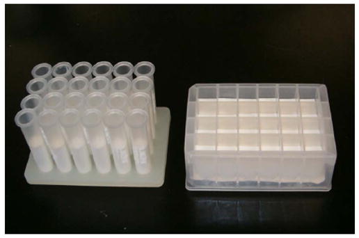
24-Cartridge (left) and 24-well (right) SPE plates
The 96-well F-SPE plate is more suitable for parallel synthesis of larger number but smaller quantity of samples. Figure 6 shows a pair of 96-well Ex-Block plates poised for plate-to-plate F-SPE.24b Each well in the top block has 3 mL volume and is charged with 1 g of fluorous silica gel. The bottom receiving well also has 3 mL volume. The 96-well plate F-SPE system has been demonstrated in gravity F-SPE with 120 μm size silica gel for fluorous scavenging reactions and amide coupling reactions.22 There are several similar 96-well plates commercially available. However, most of them only have 2 mL well volume.
Figure 6.
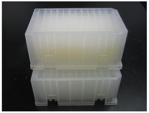
Ex-Block for 96-well plate-to-plate F-SPE
The F-SPE process can also be automated. The RapidTrace® SPE workstation has been widely used in biology labs for sample preparation,26 but it is less popular in synthetic labs (Figure 7). The workstation can have up to ten modules arranged in parallel and attached to a computer to control cartridge conditioning, sample loading, cartridge elution, and fraction collection. The automated sample loading can handle solutions and slurries containing a small amount of solid. Pump-controlled solvent delivery gives accurate solvent volume and flow rate. Each module conducts ten SPEs sequentially. A maximum of 10 × 10 = 100 SPE separations can be finished in 1–2 h unattended. Each SPE cartridge has 3 mL volume which can be charged with 1.5 g of fluorous silica gel for separation of 10–100 mg samples. Relative to the plate-to-plate SPE, the RapidTrace® unit has higher upfront instrument cost but significantly saves manpower and provides consistent results.22
Figure 7.
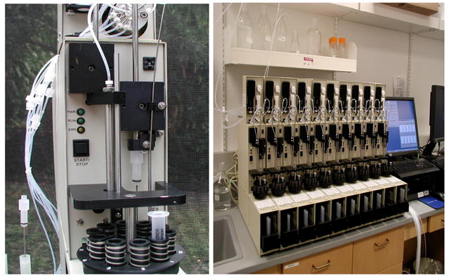
RapidTrace® SPE workstation (left, single unit; right, ten parallel units)
Commercial systems from Isco and Biotage are available for large scale F-SPE or flash chromatography. Among them, the Biotage FlashMaster™ II can handle up to 200 psi back pressure, which is more suitable for fluorous separations using MeOH-H2O and MeCN-H2O as the elution solvents. This system has ten channels; cartridge size from 5 to 100 g can be easily fit in (Figure 8). The FlashMaster™ system also has many features of standard HPLC including gradient solvent mixing, flow control, and UV-trigged fraction collection.
Figure 8.
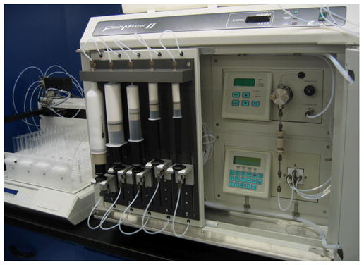
Biotage FlashMaster™ II for variable-scale F-SPE
4. Tabular summary of F-SPE
This tabular section is intended to provide a comprehensive collection of the published uses of F-SPE for separation in small molecule synthesis from its inception in 1997 up to early 2006. Small molecule synthesis is not the only use of F-SPE, but applications in oligonucleotide synthesis,27 peptide synthesis,28 proteomics29 and other areas30 are not covered here. Nor do we cover other uses for fluorous silica gel includeing HPLC demixing in fluorous mixture synthesis31 and catalyst/reagent support applications.32
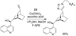
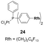
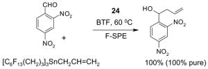
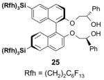
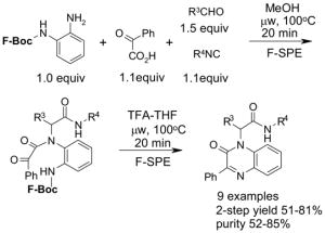
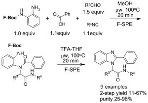
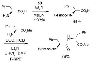
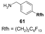
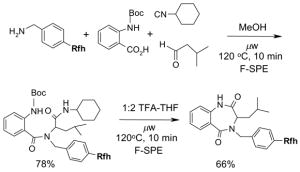
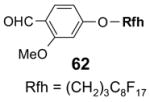
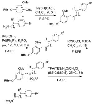
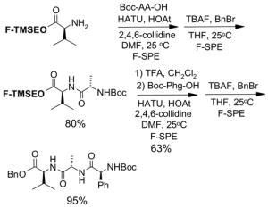
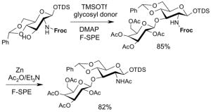
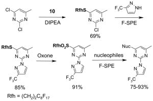
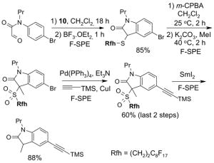
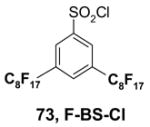
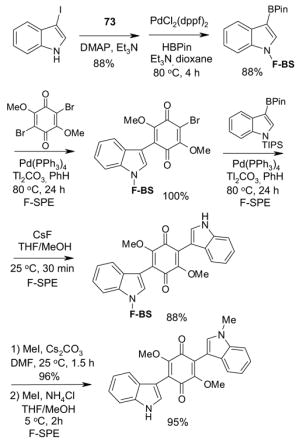
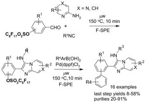
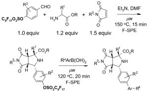
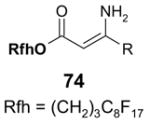
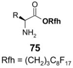
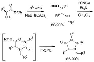
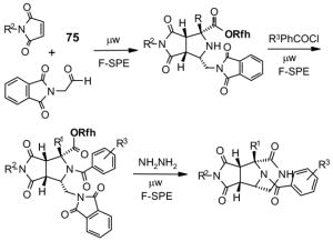
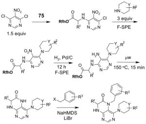
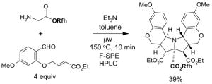
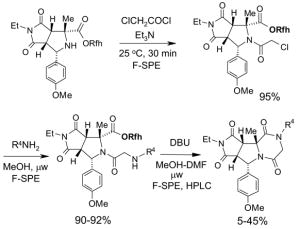
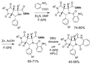
The Tables are organized so that readers can easily scan them for relevant fluorous reaction components (left column) and allied transformations (center column). References are provided in the right column. In almost all cases, papers report multiple examples of the use of F-SPE, but we often extract only a single representative example. In the case of chiral auxiliaries and protecting groups, for example, the F-SPE may be used in multiple steps, including tagging, reaction of tagged substrate and detagging. Here, we typically focus on the key reactions. In the case of library synthesis, we summarize the steps and show a generic example of the library core with R groups to give readers a sense of the scope and substitution pattern of the library.
The Tables are organized according to fluorous reaction component under the following headings:
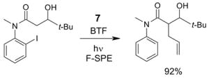
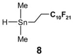
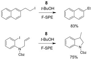
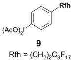
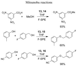
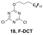
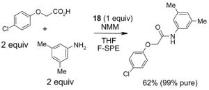
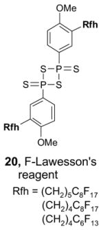
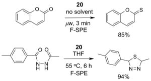
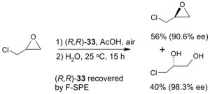
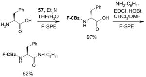
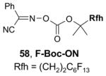
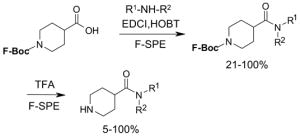
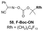
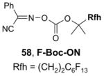
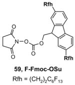
Reagents,33 Table 1: One or more fluorous reagents are used in at least stoichiometric quantities, providing fluorous byproducts. The precursor and the target product are organic.
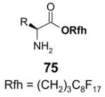
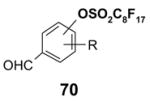
Reactants, Table 2: A fluorous reactant is incorporated into the product, but it is not a chiral auxiliary or a protecting group.
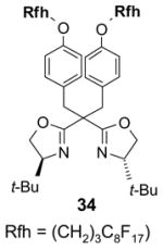
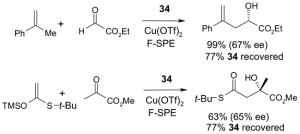
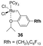
Catalysts,34 Table 3: The fluorous reaction component is a catalyst or precatalyst. The precursor and the target product are organic.
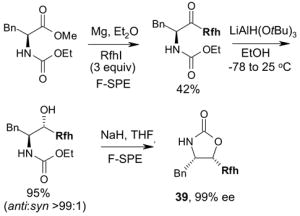
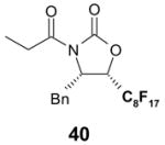
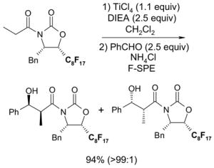
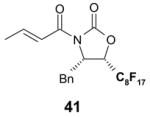
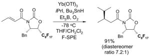
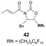
Chiral auxiliary, Table 4: The substrate and product bear a chiral auxiliary with a fluorous tag.
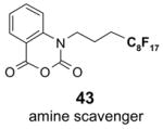
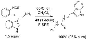
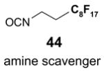
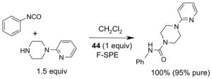
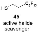
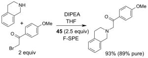
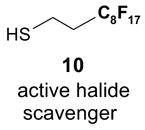
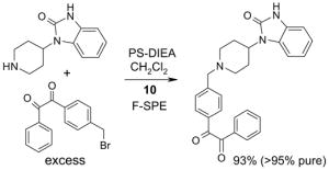
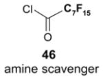
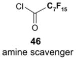
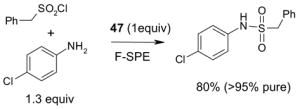
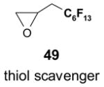
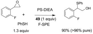
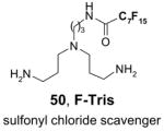
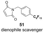
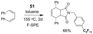
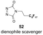
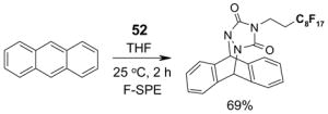
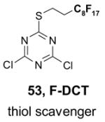
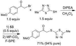
Scavengers,35 Table 5: A fluorous reagent is used to consume (scavenge) some undesired reaction component (usually an unreacted starting reagent) and the scavenged product is separated from the organic target product.
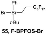
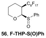
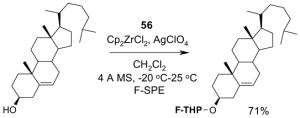
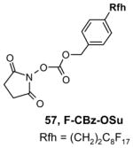
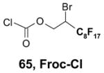
Protecting groups,36 Table 6: The substrate and/or product bear a fluorous version of a common protecting group.
Displaceable tags,36 Table 7: The substrate and derived intermediates bear a tag that is displaced with other functionalities, usually in a diversity oriented synthesis setting.
4.1. Table 1.
Reactions with fluorous reagents
4.2. Table 2.
Reactions with fluorous reactants
4.3. Table 3.
Reactions with fluorous catalysts
4.4. Table 4.
Reactions with fluorous chiral auxiliaries
4.5. Table 5.
Reactions with fluorous scavengers
4.6. Table 6.
Reactions with fluorous protecting groups
4.7. Table 7.
Reactions with fluorous displaceable tags
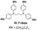
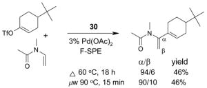
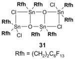
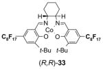
A number of the more popular fluorous reaction components shown in the tables are commercially available from Fluorous Technologies, Inc.,19 Aldrich, Fluka, and Wako (in Japan).
5. Practical Aspects of F-SPE21
5.1. A typical F-SPE procedure
F-SPEs in cartridge format are very easy to conduct and have the following general steps: cartridge washing (for new cartridges only), preconditioning, sample loading, fluorophobilc elution, fluorophilic elution, and final washing for cartridge reuse (optional). A typical F-SPE procedure for separation of a reaction mixture with a 2 g SPE cartridge is as follows:21
Step 1 – Cartridge washing: Wash a new cartridge with 1 mL of DMF under a vacuum or positive pressure depending on your SPE manifold. This step can be omitted with recycled cartridges.
Step 2 – Preconditioning: Pass through 6 mL of 80:20 MeOH:H2O to condition the cartridge. Discard the preconditioning eluent.
Step 3 – Sample loading: Dissolve sample (100–300 mg) in 0.4 mL of DMF and load onto the cartridge by using vacuum or positive pressure to ensure the sample is completely adsorbed onto the cartridge (see Table 8 for alternative loading solvents).
Step 4 – Fluorophobic elution: Wash with 6–8 mL of 80:20 MeOH:H2O to obtain the fraction containing the organic compounds.
Step 5 – Fluorophilic elution: Wash with 8 mL of MeOH to obtain the fraction containing the fluorous compounds.
Step 6 – Final washing (optional): To regenerate the SPE cartridge for reuse, wash with 6 mL of THF or acetone and air dry.
Table 8.
Suggested maximum loading solvent volumes for C8F17-tagged substrates
| Maximum loading volume | |||
|---|---|---|---|
| Solvent | 2 g cartridge | 5 g cartridge | 10 g cartridge |
| THF | 0.2 mL | 0.5 mL | 1.0 mL |
| CH2Cl2 | 0.2 mL | 0.5 mL | 1.0 mL |
| MeCN | 0.2 mL | 0.5 mL | 1.0 mL |
| MeOH | 0.2 mL | 0.5 mL | 1.0 mL |
| DMF | 0.4 mL | 1.0 mL | 2.0 mL |
| DMSO | 0.6 mL | 1.5 mL | 3.0 mL |
5.2. F-SPE Demonstration with dyes
The following dye separation demonstrates how F-SPE works. The non-fluorous compound is Solvent Blue® dye; the fluorous compound is F-orange dye. These two dyes have similar polarities. Figure 9 shows fluorous cartridges containing the dye mixture in three different stages of elution. The left-hand test-tube illustrates how the F-SPE cartridge appears after loading a mixture of the two dyes and elution with a small amount of 80:20 MeOH:H2O. The center tube shows how the non-fluorous components (blue fraction) are washed from the cartridge by using more 80:20 MeOH:H2O. The adsorbed fluorous dye is not eluted even with extensive flushing with 80:20 MeOH:H2O and remains on the cartridge. Finally, the orange fluorous dye is easily eluted with 100% MeOH or THF, as shown by the third tube.
Figure 9. F-SPE with blue (organic) and orange (fluorous) dyes.
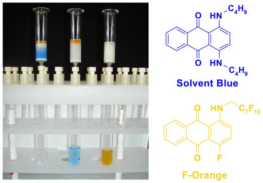
Left tube: beginning of fluorophobic wash (80:20 MeOH:H2O); Center tube: end of fluorophobic wash; Right tube: end of fluorophilic wash (100% MeOH)
5.3. Common issues related to F-SPE
5.3.1. Loading solvents
Many different solvents can be used for sample loading, however, the more fluorophilic the solvent is the smaller the volume should be to prevent breakthrough. A list of solvents with increasing fluorophilicity is as follows: H2O < DMSO < DMF < MeOH < MeCN < THF < HFC-7100 (C4F9OCH3) < FC-72. For normal F-SPE, the mass loading (weight of crude sample compared to the weight of fluorous silica gel) is suggested to be around 5–10%.21 With the least fluorophilic DMSO, the solvent loading (volume of solvent compared to the volume of fluorous silica gel) can be as high as 30%, whereas with high fluorophilic THF, the solvent loading should be less than 10% to avoid fluorous sample breakthrough. Table 8 provides recommendations for some common loading solvents and cartridge sizes.
The usual symptom of breakthrough is that a small amount of the fluorous compound comes off early in the organic fraction, but the bulk of the fluorous compound is retained on the cartridge. This happens because the loading solvent elutes the fluorous compounds, but the elution stops as soon as the fluorophobic solvent elutes the loading solvent from the cartridge. Breakthrough problems can often be solved by using less volume of loading solvent. Other solutions are to use a more fluorophobic loading solvent, to use a larger cartridge, or to lower the sample mass loading.
A good loading solvent should have low fluorophilicity and good dissolving power for organic compounds. Direct loading of a reaction mixture onto a fluorous cartridge for SPE is sometimes possible. However, in common practice, the reaction mixture is usually filtered first to remove insoluble solid and catalysts. The concentrated crude mixture is then dissolved in an appropriate loading solvent and loaded onto a cartridge preconditioned with a fluorophobic solvent. In large scale F-SPE, an aqueous workup of reaction mixture is recommended. This removes water-soluble materials and preserves the lifetime of cartridge for reuse.
5.3.2. Elution solvents
An F-SPE has two solvent passes, the first one uses the fluorophobic solvent and the second one uses the fluorophilic solvent. The fluorophobic solvent is usually a water-miscible organic solvent with certain amount of water to reduce fluorophilicity. Solvents such as 70:30 MeCN-H2O, 80:20 MeOH-H2O, and 90:10 DMF-H2O are the common choices. Acetone-H2O and THF-H2O can also serve the purpose. If a component in the reaction mixture is water sensitive, then 100% DMSO can be used for fluorophobic wash. All the non-fluorous components are expected to elute with the fluorophobic solvent in 3–5 column volumes, while fluorous components are retained on the cartridge. If organic components have low solubility in elution solvent, this can occasionally generate a precipitate and block the cartridge during F-SPE. Reduced mass loading and slightly increased the percentage of organic solvent can minimize this problem. After the elution of non-fluorous components, a more fluorophilic solvent such as MeOH, acetone, MeCN, or THF is used to wash out the fluorous component retained on the cartridge in 3–5 column volumes.
5.3.3. Fluorous silica gel reuse
To control the cost spent on fluorous silica gel and reduce waste disposal, the cartridges can be washed thoroughly and conditioned for reuse. The fluorous stationary phase can be cleaned by washing with fluorophilic solvents (acetone, MeCN, and THF) or with a mixture of MeCN-H2O containing 0.5% TFA. To extend cartridge lifetime, crude samples containing strongly acidic or basic compounds, or having insoluble solids or a large amount of salts are not recommended for directly load onto the cartridge without pretreatment. However, if the cartridge will be discarded after use, the precautions are not necessary.
5.3.4. Gravity F-SPE with large fluorous silica gel
Compared to normal F-SPE with 40 μm fluorous silica gel, the resolution of gravity F-SPE with 120 μm silica gel is reduced to some extent. Cartridges with the large size fluorous silica gel need to be carefully conditioned to remove air bubbles. In the case of plate-to-plate F-SPE, the plate loaded with a high boiling solvent such as DMF or DMSO is degassed in a vacuum chamber (20–30 mm Hg) for 3–5 min to remove the air bubbles.
6. Conclusions
The results summarized in this Report show that the new separation technique of fluorous solid-phase extraction (F-SPE) has successfully debuted and is now ready for prime time. While there is still more to be learned, basic F-SPE techniques are well understood and have proven generality. The predictability and generic “fluorous/non-fluorous” nature of F-SPE’s make them especially attractive in research settings with single compounds or compound libraries. The learning curve is not steep; indeed, you can be up and running in the lab with your first F-SPE in as little as 15–30 minutes. Fluorous silica gel is now commercially available in an assortment of sizes and formats, and an increasing number of fluorous reaction components (reagents, catalysts, tags, scavengers, protecting groups) are also sold commercially. Thus, we expect that the usefulness of F-SPE will continue to expand as it is applied to more and different problems, and we intend that this Report will help to fuel that expansion.
Acknowledgments
We thank the National Institutes of Health, National Institutes of General Medical Science, for generous grant funding (1R43GM062717-01, 2R44GM062717-02, 1R43GM066415-01, 1R43GM067326-01, and 2R43GM067326-01).
Abbreviations
- BINAP
2,2′-bis(diphenylphosphineno)-1,1′-binaphthyl
- BINOL
1,1′-bi-2,2′-naphthol
- Boc
t-butyloxycarbonyl
- BTF
benzotrifluoride
- Cbz
benzyloxycarbonyl
- CDMT
2-chloro-4,6-dimetoxy-1,3,5-triazine
- m-CPBA
meta chloroperbenzoic acid
- DCT
2,4-dichloro-1,3,5-triazine
- dba
dibenzylideneacetone
- DEAD
diethyl azodicarboxylate
- DIPEA
diisopropylethylamine
- DCC
dicyclohexylcarbodiimide
- DBU
1,8-diazabicyclo[5.4.0]undec-7-ene
- dppp
1,2-bis(diphenylphosphineno)propane
- DMF
N,N-dimethylformamide
- DMAP
4-dimethylaminopyridine
- DMSO
dimethylsulfoxide
- dppf
1,1′-bis(diphenylphosphineno)ferrocene
- FC-72
perfluorohexanes
- F-SPE
fluorous solid-phase extraction
- FTI
Fluorous Technologies, Inc
- HFE-7100
perfluorobutyl methyl ether
- HOAT
1-hydroxy-7-azabenzotriazole
- HOBT
1-hydroxybenzotriazole
- HPLC
high-performance liquid chromatography
- LLE
liquid-liquid separation
- MOM
methoxymethyl
- μw
microwave
- NIS
N-iodosuccinimide
- Oxone
potassium peroxymonosulfate
- Rf
perfluoroalkyl group
- Rfh
perfluoroalkyl group with CH2 spacer
- TEA
triethylamine
- TFA
trifluoroacetic acid
- THF
tetrahydrofuran
- THP
2-tetrahydropyranyl
- TLC
thin-layer chromatography
- TMS
trimethylsilyl
- TPP
triphenylphosphine
References and Notes
- 1.a) Curran DP. Chemtracts—Org Chem. 1996;9:75–87. [Google Scholar]; b) Curran DP. Angew Chem, Int Ed Eng. 1998;37:1175–1196. [Google Scholar]; c) Yoshida J, Itami K. Chem Rev. 2002;102:3693–3716. doi: 10.1021/cr0103524. [DOI] [PubMed] [Google Scholar]; d) Tzschucke CC, Markert C, Bannwarth W, Roller S, Hebel A, Haag R. Angew Chem Int Ed. 2002;41:3964–4000. doi: 10.1002/1521-3773(20021104)41:21<3964::AID-ANIE3964>3.0.CO;2-3. [DOI] [PubMed] [Google Scholar]
- 2.Wender PA, Handy ST, Wright DL. Chem Ind London. 1997:765. [Google Scholar]
- 3.Curran DP, Hadida S, He M. J Org Chem. 1997;62:6714–6715. [Google Scholar]
- 4.Previous reviews covering aspects of fluorous silica gel and F-SPE: Curran DP. Synlett. 2001:1488–1496.Curran DP. In: Handbook of Fluorous Chemistry. Gladysz JA, Curran DP, Horvath IT, editors. Wiley-VCH; Weinheim: 2004. pp. 101–127.
- 5.a) Horvath IT, Rabai J. Science. 1994;266:72–75. doi: 10.1126/science.266.5182.72. [DOI] [PubMed] [Google Scholar]; b) Horvath IT. In: Aqueous-Phase Organometallic Catalysis. 2. Cornils B, Hermann WA, editors. Wiley; Weinheim: 2004. pp. 646–654. [Google Scholar]
- 6.a) Overview of the field: Gladysz JA, Curran DP, Horvath IT, editors. Handbook of Fluorous Chemistry. Wiley-VCH; Weinheim: 2004. b) Scope and definition of terms: Horvath IT, Curran DP, Gladysz JA. In: Handbook of Fluorous Chemistry. Gladysz JA, Curran DP, Horvath IT, editors. Wiley-VCH; Weinheim: 2004. pp. 1–4.
- 7.Nakamura H, Linclau B, Curran DP. J Am Chem Soc. 2001;123:10119–10120. doi: 10.1021/ja011716c. [DOI] [PubMed] [Google Scholar]
- 8.Gladysz JA, Correa de Costa R. In: Handbook of Fluorous Chemistry. Gladysz JA, Curran DP, Horvath IT, editors. Wiley-VCH; Weinheim: 2004. pp. 24–40. [Google Scholar]
- 9.a) Curran DP, Luo ZY. J Am Chem Soc. 1999;121:9069–9072. [Google Scholar]; b) Zhang Q, Luo Z, Curran DP. J Org Chem. 2000;65:8866–8873. doi: 10.1021/jo000464f. [DOI] [PubMed] [Google Scholar]
- 10.Reviews of light fluorous chemistry: Zhang W. Tetrahedron. 2003;59:4475–4489.Zhang W. Chem Rev. 2004;104:2531–2556. doi: 10.1021/cr030600r.Curran DP. In: Handbook of Fluorous Chemistry. Gladysz JA, Curran DP, Horvath IT, editors. Wiley-VCH; Weinheim: 2004. pp. 128–156.Curran DP. Aldrichmica Acta. 2006;39:3–9.
- 11.Grubbs RH. Handbook of Metathesis. Wiley-VCH; Chichester, England: 2003. [Google Scholar]
- 12.Yao QW, Zhang YL. J Am Chem Soc. 2004;126:74–75. doi: 10.1021/ja037394p. [DOI] [PubMed] [Google Scholar]
- 13.Matsugi M, Curran DP. J Org Chem. 2005;70:1636–1642. doi: 10.1021/jo048001n. [DOI] [PubMed] [Google Scholar]
- 14.a) Fukui Y, Brueckner AM, Shin Y, Balachandran R, Day BW, Curran DP. Org Lett. 2006;8:301–304. doi: 10.1021/ol0526827. [DOI] [PubMed] [Google Scholar]; b) Moura-Letts G. University of Pittsburgh: unpublished results. [Google Scholar]
- 15.These and many other separation techniques have been compared and contrasted in detail in the setting of Mitsunobu reactions: Dandapani S, Curran DP. Chem Eur J. 2004;10:3130–3138. doi: 10.1002/chem.200400363.Dembinski R. Eur J Org Chem. 2004:2763–2772.
- 16.a) Gladysz JA. In: Handbook of Fluorous Chemistry. Gladysz JA, Curran DP, Horvath IT, editors. Wiley-VCH; Weinheim: 2004. pp. 41–55. [Google Scholar]; b) Curran DP, Wang XA, Zhang QS. J Org Chem. 2005;70:3716–3719. doi: 10.1021/jo050116j. [DOI] [PubMed] [Google Scholar]; c) Chen CHT, Zhang W. Molecular Diversity. 2005;9:353–359. doi: 10.1007/s11030-005-8104-3. [DOI] [PMC free article] [PubMed] [Google Scholar]
- 17.Matsugi M, Curran DP. Org Lett. 2004;6:2717–2720. doi: 10.1021/ol049040o. [DOI] [PubMed] [Google Scholar]
- 18.Majors RE. LC GC Mag Separation Sci. 1998:8.Handley AJ, McDowall RD. In: Extraction Methods in Organic Analysis. Handley AJ, editor. Sheffield Academic Press; Sheffield: 1999. pp. 54–74.c) For a special issue on SPE for sample preparations, see: Poole CF, Wilson ID. J Chromatogr A. 2000;885:1–471. doi: 10.1016/s0021-9673(00)00224-7.
- 19.a) www.fluorous.com; b) DPC founded FTI and owns an equity interest in the company.
- 20.Reviews covering fluorous solvents: Gladysz JA, Emnet C. In: Handbook of Fluorous Chemistry. Gladysz JA, Curran DP, Horvath IT, editors. Wiley-VCH; Weinheim: 2004. pp. 11–23.Ryu I, Matsubara H, Emnet C, Gladysz JA, Takeuchi S, Nakamura Y, Curran DP. In: Green Reaction Media in Organic Synthesis. Mikami K, editor. Blackwell; Oxford: 2005. pp. 59–124.
- 21.For details of F-SPE procedures, see FTI Application Notes: http://fluorous.com/download/FTI_AppNote_F-SPE.pdf
- 22.FTI unpublished results.
- 23.VacMaster®-96 SPE manifold and FlashMaster™ II are products of Biotage (www.biotage.com).
- 24.a) Whatman® 24-well (10 mL) receiving plates, product number 7701-51022 (www.whatman.com). b) 96-Well Ex-Block is a product of Exelixis, Inc. (www.exelixis.com).
- 25.Zhang W, Lu Y, Nagashima T. J Comb Chem. 2005;7:893–897. doi: 10.1021/cc050061z. [DOI] [PMC free article] [PubMed] [Google Scholar]
- 26.RapidTrace® system is available form Caliper Life Sciences (www.caliperls.com).
- 27.a) Pearson WH, Berry DA, Stoy P, Jung KY, Sercel AD. J Org Chem. 2005;70:7114–7122. doi: 10.1021/jo050795y. [DOI] [PubMed] [Google Scholar]; b) Beller C, Bannwarth W. Helv Chim Acta. 2005;88:171–179. [Google Scholar]
- 28.a) Filippov DV, van Zoelen DJ, Oldfield SP, van der Marel GA, Overkleeft HS, Drijfhout JW, van Boom JH. Tetrahedron Lett. 2002;43:7809–7812. [Google Scholar]; b) de Visser PC, van Helden M, Filippov DV, van der Marel GA, Drijfhout JW, van Boom JH, Noort D, Overkleeft HS. Tetrahedron Lett. 2003;44:9013–9016. [Google Scholar]
- 29.Brittain SM, Ficarro SB, Broack S, Peters EC. Nature Biotechnology. 2005;23:463–468. doi: 10.1038/nbt1076. [DOI] [PubMed] [Google Scholar]
- 30.Palmacci ER, Hewitt MC, Seeberger PH. Angew Chem Int Ed. 2001;40:4433–37. doi: 10.1002/1521-3773(20011203)40:23<4433::aid-anie4433>3.0.co;2-8. [DOI] [PubMed] [Google Scholar]
- 31.Luo ZY, Zhang QS, Oderaotoshi Y, Curran DP. Science. 2001;291:1766–1769. doi: 10.1126/science.1057567.b) Short review: Zhang W. Arkivoc. 2004;(i):101–109.
- 32.Horn J, Michalek F, Tzschucke CC, Bannwarth W. Topics in Curr Chem. 2004;242:43–75. doi: 10.1007/b96873. [DOI] [PubMed] [Google Scholar]
- 33.Dandapani S. In: Handbook of Fluorous Chemistry. Gladysz JA, Curran DP, Horvath IT, editors. Wiley-VCH; Weinheim: 2004. pp. 175–182. [Google Scholar]
- 34.a) Barthel-Rosa LP, Gladysz JA. Coordination Chem Rev. 1999;190–192:587–605. [Google Scholar]; b) de Wolf E, van Koten G, Deelman BJ. Chem Soc Rev. 1999;28:37–41. [Google Scholar]; c) Cavazzinni M, Montannari F, Pozzi G, Quici S. J Fluorine Chem. 1999;94:183. [Google Scholar]
- 35.Lindsley CW, Leister WH. In: Handbook of Fluorous Chemistry. Gladysz JA, Curran DP, Horvath IT, editors. Wiley-VCH; Weinheim: 2004. pp. 236–246. [Google Scholar]
- 36.a) Zhang W. In: Handbook of Fluorous Chemistry. Gladysz JA, Curran DP, Horvath IT, editors. Wiley-VCH; Weinheim: 2004. pp. 222–235. [Google Scholar]; b) Zhang W. Curr Opin Drug Disc Dev. 2004;7:784–797. [PMC free article] [PubMed] [Google Scholar]
- 37.Curran DP, Luo Z, Degenkolb P. Bioorg Med Chem Lett. 1998;8:2403–2408. doi: 10.1016/s0960-894x(98)00435-1. [DOI] [PubMed] [Google Scholar]
- 38.Curran DP, Hadida S, Kim SY, Luo ZY. J Am Chem Soc. 1999;121:6607–6615. [Google Scholar]
- 39.Lindsley CW, Zhang Z. In: Handbook of Fluorous Chemistry. Gladysz JA, Curran DP, Horvath IT, editors. Wiley-VCH; Weinheim: 2004. pp. 371–373. [Google Scholar]
- 40.Christensen C, Clausen RP, Begtrup M, Kristensen JL. Tetrahedron Lett. 2004;45:7991–7993. [Google Scholar]
- 41.Barthelemy B, Schneider S, Bannwarth W. Tetrahedron Lett. 2002;43:807–810. [Google Scholar]
- 42.Lindsley CW, Zhao Z, Newton RC, Leister WH, Strauss KA. Tetrahedron Lett. 2002:4467–4470. [Google Scholar]
- 43.Dandapani S, Curran DP. Tetrahedron. 2002;58:3855–3864. [Google Scholar]
- 44.Dandapani S, Curran DP. J Org Chem. 2004;69:8751–8757. doi: 10.1021/jo0488098. [DOI] [PubMed] [Google Scholar]
- 45.Desai B, Dallinger D, Kappe CO. Tetrahedron. 2006;62:4651–4664. [Google Scholar]
- 46.Zhang W, Lu Y. QSAR Comb Sci. 2006 doi: 10.1002/qsar.200640041. in press. [DOI] [PMC free article] [PubMed] [Google Scholar]
- 47.Nagashima T, Lu YM, Petro MJ, Zhang W. Tetrahedron Lett. 2005;46:6585–6588. doi: 10.1016/j.tetlet.2005.07.072. [DOI] [PMC free article] [PubMed] [Google Scholar]
- 48.Dalicsek Z, Pollreisz F, Gomory A, Soos T. Org Lett. 2006;8:1093–1095. doi: 10.1021/ol051024j. [DOI] [PubMed] [Google Scholar]
- 49.Kaleta Z, Makowski BT, Soos T, Dembinski R. Org Lett. 2006;8:1625–1628. doi: 10.1021/ol060208a. [DOI] [PubMed] [Google Scholar]
- 50.Kainz S, Luo ZY, Curran DP, Leitner W. Synthesis. 1998:1425–1427. [Google Scholar]
- 51.Ryu I, Kreimerman S, Niguma T, Minakata S, Komatsu M, Luo ZY, Curran DP. Tetrahedron Lett. 2001;42:947–950. [Google Scholar]
- 52.Kaleta Z, Egyed O, Soos T. Org Biomol Chem. 2005;3:2228–2230. doi: 10.1039/b504973c. [DOI] [PubMed] [Google Scholar]
- 53.Nakamura Y, Takeuchi S, Ohgo Y, Curran DP. Tetrahedron. 2000;56:351–356. [Google Scholar]
- 54.Nakamura Y, Takeuchi S, Okumura K, Ohgo Y, Curran DP. Tetrahedron. 2002;58:3963–3969. [Google Scholar]
- 55.Fawcett J, Hope EG, Stuart AM, West AJ. Green Chem. 2005;7:316–320. [Google Scholar]
- 56.Hope EG, Stuart AM, West AJ. Green Chem. 2004;6:345–350. [Google Scholar]
- 57.Nakamura Y, Takeuchi S, Okumura K, Ohgo Y. Tetrahedron. 2001;57:5565–5571. [Google Scholar]
- 58.Vallin KSA, Zhang QS, Larhed M, Curran DP, Hallberg A. J Org Chem. 2003;68:6639–6645. doi: 10.1021/jo034265i. [DOI] [PubMed] [Google Scholar]
- 59.Beeler AB, Acquilano DE, Su Q, Yan F, Roth BL, Panek JS, Porco JA., Jr J Comb Chem. 2005;7:673–681. doi: 10.1021/cc050064b. [DOI] [PubMed] [Google Scholar]
- 60.Bucher B, Curran DP. Tetrahedron Lett. 2000;41:9617–9621. [Google Scholar]
- 61.Cavazzini M, Quici S, Pozzi G. Tetrahedron. 2002;58:3943–3949. [Google Scholar]
- 62.Simonelli B, Orlandi S, Benaglia M, Pozzi G. Eur J Org Chem. 2004:2669–2673. [Google Scholar]
- 63.Croxtall B, Hope EG, Stuart AM. Chem Commun. 2003:2430–2431. doi: 10.1039/b308543k. [DOI] [PubMed] [Google Scholar]
- 64.Curran DP, Fischer K, Moura-Letts GA. Synlett. 2004:1379–1382. [Google Scholar]
- 65.Dalicsek Z, Pollreisz F, Gomory A, Soos T. Org Lett. 2005;7:3243–3246. doi: 10.1021/ol051024j. [DOI] [PubMed] [Google Scholar]
- 66.Hein JE, Geary LM, Jaworski AA, Hultin PG. J Org Chem. 2005;70:9940–9946. doi: 10.1021/jo051696n. [DOI] [PubMed] [Google Scholar]
- 67.Hein JE, Hultin PG. Synlett. 2003:635–638. [Google Scholar]
- 68.Hein JE, Zimmerman J, Sibi MP, Hultin PG. Org Lett. 2005;7:2755–2758. doi: 10.1021/ol050956k. [DOI] [PMC free article] [PubMed] [Google Scholar]
- 69.Hein JE, Hultin PG. Tetrahedron: Asym. 2005;16:2341–2347. [Google Scholar]
- 70.Zhang W, Chen CHT, Nagashima T. Tetrahedron Lett. 2003;44:2065–2068. [Google Scholar]
- 71.Zhang W, Curran DP, Chen CHT. Tetrahedron. 2002;58:3871–3875. [Google Scholar]
- 72.Lindsley CW, Zhao Z, Leister WH, Robinson RG, Barnett SF, Defeo-Jones D, Jones RE, Huber HE. Bioorg Med Chem Lett. 2005;15:761–764. doi: 10.1016/j.bmcl.2004.11.011. [DOI] [PubMed] [Google Scholar]
- 73.Lindsley CW, Bogusky MJ, Leister WH, McClain RT, Robinson RG, Barnett SF, Defeo-Jones D, Hartman GD. Tetrahedron Lett. 2005;46:2779–2782. [Google Scholar]
- 74.Lindsley CW, Zhao Z, Leister WH. Tetrahedron Lett. 2002;43:4225–4228. [Google Scholar]
- 75.Zhang AS, Elmore CS, Egan MA, Melillo DG, Dean DC. J Labelled Comp Radiopharma. 2005;48:203–208. [Google Scholar]
- 76.Lindsley CW, Zhao Z, Leister WH, Strauss KA. Tetrahedron Lett. 2002;43:6319–6323. [Google Scholar]
- 77.Werner S, Curran DP. Org Lett. 2003;5:3293–3296. doi: 10.1021/ol035214a. [DOI] [PubMed] [Google Scholar]
- 78.Lu Y, Zhang W. QSAR Comb Sci. 2006 doi: 10.1002/qsar.200640041. in press. [DOI] [PMC free article] [PubMed] [Google Scholar]
- 79.Rover S, Wipf P. Tetrahedron Lett. 1999;40:5667–5670. [Google Scholar]
- 80.Wipf P, Reeves JT, Rover S. 06673539. US Patent. 2004
- 81.Wipf P, Reeves JT. Tetrahedron Lett. 1999;40:4649–4652. [Google Scholar]
- 82.Curran DP, Amatore M, Guthrie D, Campbell M, Go E, Luo ZY. J Org Chem. 2003;68:4643–4647. doi: 10.1021/jo0344283. [DOI] [PubMed] [Google Scholar]
- 83.Luo ZY, Williams J, Read RW, Curran DP. J Org Chem. 2001;66:4261–4266. doi: 10.1021/jo010111w. [DOI] [PubMed] [Google Scholar]
- 84.Zhang W, Tempest P. Tetrahedron Lett. 2004;45:6757–6760. [Google Scholar]
- 85.Matsugi M, Yamanaka K, Inomata I, Takekoshi N, Hasegawa M, Curran DP. QSAR Comb Sci. 2006 in press. [Google Scholar]
- 86.Curran DP, Ogoe C. QSAR Comb Sci. 2006 in press. [Google Scholar]
- 87.Zhang, W., unpublished results.
- 88.Villard AL, Warrington BH, Ladlow M. J Comb Chem. 2004;6:611–622. doi: 10.1021/cc0499338. [DOI] [PubMed] [Google Scholar]
- 89.Fustero S, Sancho AG, Chiva G, Sanz-Cervera JF, del Pozo C, Aceña JL. J Org Chem. 2006;71:3299–3302. doi: 10.1021/jo052569u. [DOI] [PubMed] [Google Scholar]
- 90.Manzoni L, Castelli R. Org Lett. 2006;8:955–957. doi: 10.1021/ol060006e. [DOI] [PubMed] [Google Scholar]
- 91.Jing Y, Huang X. Tetrahedron Lett. 2004;45:4615–4618. [Google Scholar]
- 92.Manzoni L. Chem Commun. 2003:2930–2931. doi: 10.1039/b311448a. [DOI] [PubMed] [Google Scholar]
- 93.Manzoni L, Castelli R. Org Lett. 2004;6:4195–4198. doi: 10.1021/ol048474g. [DOI] [PubMed] [Google Scholar]
- 94.Donovan A, Forbes J, Dorff P, Schaffer P, Babich J, Valliant JF. J Am Chem Soc. 2006;128:3536–3537. doi: 10.1021/ja0600375. [DOI] [PubMed] [Google Scholar]
- 95.Zhang W, Chen CHT, Lu Y, Nagashima T. Org Lett. 2004;6:1473–1476. doi: 10.1021/ol0496428. [DOI] [PMC free article] [PubMed] [Google Scholar]
- 96.Zhang W, Lu Y, Chen CHT. Mol Diversity. 2003;7:199–202. doi: 10.1023/b:modi.0000006825.12186.5f. [DOI] [PMC free article] [PubMed] [Google Scholar]
- 97.Zhang W, Nagashima T, Lu Y, Chen CHT. Tetrahedron Lett. 2004;45:4611–4613. [Google Scholar]
- 98.Zhang W, Nagashima T. J Fluorine Chem. 2006;127:588–591. doi: 10.1016/j.jfluchem.2005.11.006. [DOI] [PMC free article] [PubMed] [Google Scholar]
- 99.Cioffi CL, Berlin ML, Herr RJ. Synlett. 2004:841–845. [Google Scholar]
- 100.Chen CHT, Zhang W. Org Lett. 2003;5:1015–1017. doi: 10.1021/ol0274864. [DOI] [PMC free article] [PubMed] [Google Scholar]
- 101.Zhang W. Org Lett. 2003;5:1011–1014. doi: 10.1021/ol027469e. [DOI] [PMC free article] [PubMed] [Google Scholar]
- 102.McAllister LA, McCormick RA, Brand S, Procter DJ. Angew Chem Int Ed. 2005;44:452–455. doi: 10.1002/anie.200461930. [DOI] [PubMed] [Google Scholar]
- 103.Kasahara T, Kondo Y. Chem Commn. 2006:891–893. doi: 10.1039/b516487g. [DOI] [PubMed] [Google Scholar]
- 104.Lu Y, Zhang W. QSAR Comb Sci. 2004;23:827–835. doi: 10.1901/jaba.2004.23-827. [DOI] [PMC free article] [PubMed] [Google Scholar]
- 105.Zhang W, Chen CHT. Tetrahedron Lett. 2005;46:1807–1810. [Google Scholar]
- 106.Fustero S, Catalán S, Flores S, Jiménez D, del Pozo C, Aceña JL, Sanz-Cervera JF, Mérida S. QSAR Comb Sci. 2006 in press. [Google Scholar]
- 107.a) Zhang W, Lu Y. Org Lett. 2003;5:2555–2558. doi: 10.1021/ol034854a. [DOI] [PMC free article] [PubMed] [Google Scholar]; b) Lu Y, Zhang W. Mol Diversity. 2005;9:91–98. doi: 10.1007/s11030-005-1293-y. [DOI] [PMC free article] [PubMed] [Google Scholar]
- 108.Zhang, W.; Nagashima, T. unpublished results.
- 109.Nagashima T, Zhang W. J Comb Chem. 2004;6:942–949. doi: 10.1021/cc049885r. [DOI] [PubMed] [Google Scholar]
- 110.Zhang W, Lu Y, Geib S. Org Lett. 2005;7:2269–2272. doi: 10.1021/ol0507773. [DOI] [PubMed] [Google Scholar]
- 111.Zhang W, Lu Y, Chen CHT, Curran DP, Geib S. Eur J Org Chem. 2006:2055–2059. doi: 10.1002/ejoc.200600077. [DOI] [PMC free article] [PubMed] [Google Scholar]


