Abstract
We show that it is possible to direct particles entrained in a fluid along trajectories much like rays of light in classical optics. A microstructured, asymmetric post array forms the core hydrodynamic element and is used as a building block to construct microfluidic metamaterials and to demonstrate refractive, focusing, and dispersive pathways for flowing beads and cells. The core element is based on the concept of deterministic lateral displacement where particles choose different paths through the asymmetric array based on their size: Particles larger than a critical size are displaced laterally at each row by a post and move along the asymmetric axis at an angle to the flow, while smaller particles move along streamline paths. We create compound elements with complex particle handling modes by tiling this core element using multiple transformation operations; we show that particle trajectories can be bent at an interface between two elements and that particles can be focused into hydrodynamic jets by using a single inlet port. Although particles propagate through these elements in a way that strongly resembles light rays propagating through optical elements, there are unique differences in the paths of our particles as compared with photons. The unusual aspects of these modular, microfluidic metamaterials form a rich design toolkit for mixing, separating, and analyzing cells and functional beads on-chip.
Keywords: concentration, microfluidics, nanofluidics, optics, separation
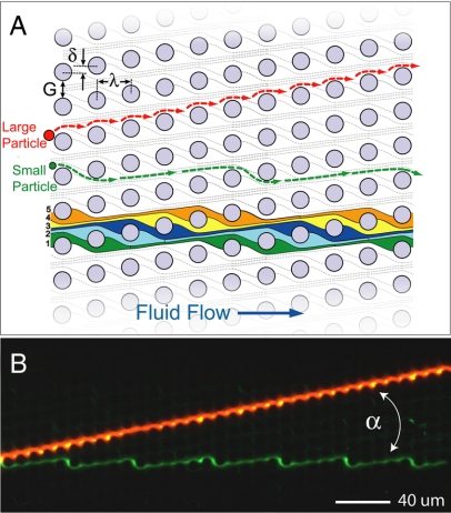
Our first understanding of optics came from viewing light as particles that moved in straight lines and refracted into media in which the speed of light was material-dependent (1). Here, we show that objects moving through a structured, anisotropic hydrodynamic medium in laminar, high-Péclet-number flow (2, 3) move along trajectories that resemble light rays in optics. One example is the periodic, microfabricated post array known as the deterministic lateral displacement (DLD) array (4), a high-resolution microfluidic particle sorter. This post array is asymmetric; each successive downstream row is shifted relative to the previous row so that the array axis forms an angle α relative to the channel walls and direction of fluid flow (Fig. 1). During operation, particles greater than some critical size are displaced laterally at each row by a post and follow a deterministic path through the array in the so-called “bumping” mode. The trajectory of bumping particles follows the array axis angle α. Particles smaller than the critical size follow the flow streamlines, weaving through the post array in a periodic “zigzag” mode.
Fig. 1.
Size-based particle separation in an asymmetric array of posts. (A) Schematic of a deterministic lateral displacement (DLD) array showing definitions of the array parameters: The posts are periodically arranged with spacing λ; each downstream row is offset laterally from the previous row by the amount δ breaking the symmetry of the array. This array axis forms an angle α = tan−1(δ/λ) = tan−1(ε) with respect to the channel walls and therefore the direction of fluid flow. Because of the array asymmetry, fluid flow in the gaps between the posts G is partitioned into 1/ε slots delineated with individual colors. Each of these slots repeats every 1/ε rows so the flow through the array is on average straight. Particles transiting the gap near a post can be displaced into an adjacent streamline (from slot 1 to slot 2) if the particles radius is larger than the slot width in the gap. Therefore, larger particles (red) are deterministically displaced at each post and migrate at an angle α to the flow. Smaller particles (green) simply follow the streamline paths and flow through the array. (B) Separation of 2.7-μm red fluorescent beads and 1.0-μm green fluorescent beads by using the array (α = 11.3°, G = 4 μm, λ = 11 μm).
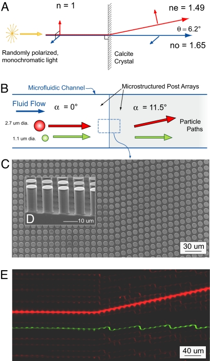
This hydrodynamic medium is effectively birefringent, where particle size replaces the concept of polarization: Particles greater than a critical size can be made to move at an angle α with respect to the flow axis, in analogy to the extraordinary rays in birefringent optical media (5), whereas particles below a critical size move with the flow. A ray diagram of optical birefringence in calcite crystal is shown in Fig. 2A. Surprisingly, randomly polarized, normally incident, monochromatic light splits into two components upon entering the crystal. The vertically polarized, extraordinary ray refracts away from the normal while the horizontal polarization continues through with no refraction. Fig. 2 B–E demonstrates size-based birefringence of particles flowing through a hydrodynamic medium of channel-spanning microfabricated posts. Two differently sized particles are normally incident on an interface between a symmetric post array (left half of channel) and an asymmetric post array (right half). Pressure-driven fluid flow through the arrays is from left to right, its overall direction determined by the larger microfluidic channel. In the symmetric media, the fluorescent particles trace out paths that match the flow direction. However, in the asymmetric section the particles propagate along different paths that depend on their size. The single, 2.7-μm red fluorescent bead deflects from the normal, tracking along the array angle (α = 11.3°) in the bumping mode, whereas the smaller, 1.1-μm red fluorescent particles follow streamline paths in the zigzag mode (one such particle trace is highlighted in green for clarity.) Therefore, in addition to size-based particle separation within an individual asymmetric array element, transitions between elements can be used to abruptly change particle trajectories. With the birefringent element as a building block it is possible to construct more complex microfluidic metamaterials with specific functions for refracting, focusing, and dispersing streams of particles.
Fig. 2.
Optical and microfluidic birefringent interfaces. (A) Optical birefringence in a calcite crystal: normally incident, randomly polarized light, incident on the anisotropic crystal splits into two polarization dependent paths. Remarkably, the extraordinary ray, whose polarization is parallel to the calcite optical axis, is deflected away from the normal. (B) Schematic of particle trajectories at the interface between a neutral region and a microfluidic metamaterial element. Particles larger than a critical size follow the array asymmetry, whereas smaller particle follow the fluid flow. (C) The simplest metamaterial element is an asymmetric array of posts tilted at an angle +α relative to the channel walls and bulk fluid flow. Shown is a top-view scanning electron micrograph (SEM) of the interface between a neutral array (α = 0°) and an array with array angle α = 11.3° (the gap G = 4 μm and post pitch λ = 11 μm are the same for both sides). (D) Cross-sectional SEM image showing the microfabricated post array. (E) Equivalent microfluidic birefringence based on particle size showing the time-trace of a 2.7-μm red fluorescent transiting the interface and being deflected from the normal [see supporting information (SI) Movie S1]. Smaller, 1.1-μm red beads are not deflected at the interface; one such trace is highlighted in green to increase contrast.
Array elements can be tailored to direct specific particle sizes at an angle to the flow by building arrays with design parameters shown in Fig. 1A, which include obstacle size D, spacing between the posts G, and post pitch λ. Asymmetry is determined by the magnitude of the row-to-row shift δ and is characterized by the slope ε = δ/λ. The final array angle is then α = tan−1(ε). For a given array angle, the critical particle size for the bumping mode is determined by the ratio between the particle diameter and the post spacing or gap. This critical particle size has been previously delineated for a range of array angles between 1.0° and 16° (6). For a given gap size, the critical size of bumping is larger at steeper angles. By using these design criteria, streams of beads, cells, and DNA have all been moved deterministically for size-based separation applications (4, 7). For the example given in Fig. 1, which has an array angle of 11.3°, gap G = 4 μm, and post pitch λ = 11 μm, the threshold particle size is ≈2.4 μm. Therefore, 2.7-μm beads travel along the array axis angle in the bumping mode, and the 1.0-μm green beads travel along streamlines in the zigzag mode, as shown. The array elements and any ancillary microfluidic channels and reservoirs are fabricated in silicon wafers by using standard microfabrication techniques including photolithography and etching. Arrays can also be molded in PDMS by using a similarly crafted silicon master. For the silicon etch, an optimized deep reactive ion etch (DRIE) is used to maintain smooth, vertical side walls, ensuring uniform top-to-bottom spacing between posts (Fig. 2D).
Results
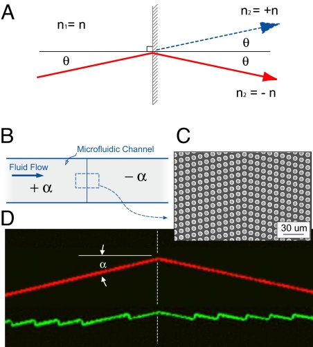
Generally, the term metamaterial describes structured periodic features designed to achieve performance beyond that of conventional materials (8). Although typically defined in electromagnetics (9, 10), we apply the broader definition to microfluidics and design a microstructured medium that enables the motion of particles across nonmixing streamlines and along trajectories different from the bulk fluid flow. For example, two birefringent elements can be connected in series to change the angle of a particle's trajectory through the metamedia. Fig. 3 shows an element with a +α array angle followed by an identical element but having an array angle −α creating a prismatic element that refracts particle trajectories at the interface between the two elements. Here, particles larger that the critical size incident from the right are refracted to the same side of the normal (red trace), analogous to optical negative refraction. Particles smaller than the critical size travel in the zigzag mode (green trace) and follow the streamline flow across the interface.
Fig. 3.
Optical and microfluidic negative refraction. (A) Refraction of light at the interface between materials having same refractive index for both identical (blue, normal refraction) or opposite (red, negative refraction) signs. (B) Two birefringent microfluidic elements are connected in series form a prismatic metamaterial. The compound element is made by joining a +α array (upstream) to a −α array (downstream). (C) Top-view SEM of the interface between the two subelements. (D) False color, epifluorescent time exposure of a supercritical, 2.7-μm-diameter fluorescent particle (top trace, red) moving from the left to the right and refracting the boundary, and a subcritical, 1.0-μm particle (bottom trace, green) following the characteristic zigzag path across the interface (see Movie S2).
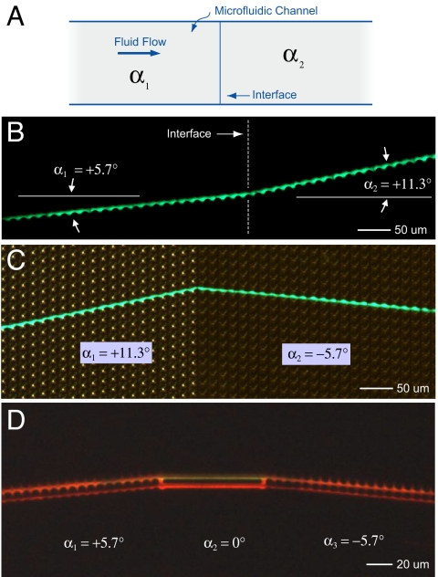
Additionally, connecting elements with different array angles can be used to construct a wide variety of interfaces. Fig. 4 illustrates three possible microfluidic metamaterial interfaces. Fig. 4A shows positive path deflection at an interface for particles larger than the critical size, analogous to the usual, positive refraction of light. Here, the interface is between two +α elements that differ only by the magnitude of the array angle. Initially, the particle trajectory is along the angle +α1 = +5.7° defined by the first element; at the interface with the second element, the particle tracks along the angle +α1 = +11.3° defined by the second element. Fig. 4B shows a similar interface, but the sign of the second array has been switched so that the deflection is negative to the normal. An external, directional lamp was used in addition to the fluorescent particle trace to highlight the physical post array. Multiple interfaces can be joined together to create more complex particle paths. Three distinct elements separated by two interfaces are shown in Fig. 4C: A straight, channel-like linking element (α = 0°) is sandwiched between two bump elements with array angles of α = +5.7° and α = −5.7°, respectively. This example shows that particles streams can directed along the flow direction for a predetermined distance.
Fig. 4.
Particle steering using arrays with different angles. (A) Schematic of a microfluidic channel showing the interface between two elements with different array axis angles, α1 and α2. (B) Time trace of a single, 3.7-μm diameter fluorescent bead crossing an interface between two arrays having the same post pitch (λ = 20 μm) and spacing (G = 5 μm), but with different array angles. The bead initially moves along a trajectory α1 = +5.7° before crossing into an element where the array angle is larger (α2 = 11.3°) but still positive. (C) Time trace of a 3.7-μm bead moving from an array with a positive array angle (α1 = 11.3°) into an array with a shallower and negative angle (α2 = −5.7°). Here, in addition to the fluorescent image of the moving bead, an external directional lamp was used to illuminate the post array and highlight the difference between the upstream and downstream elements. (D) The interface between elements can also made such that particles travel straight for a predetermined distance. Here, a stream of 1.3-μm fluorescent beads first travels along an array angle of +5.7° (with λ = 8 μm and G = 2.0 μm), then transits entering a short horizontal section (in this case linking channels) before finally entering a third array element with angle −5.7°.
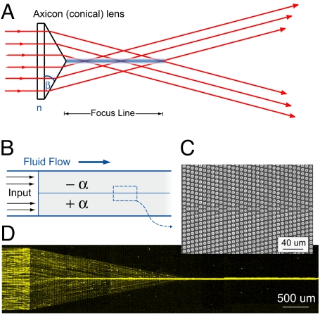
Alternatively, the +α and −α elements can be stacked vertically, as shown in Fig. 5B, to create a particle-focusing element. If the −α element lies on top of the +α element, the new metamaterial element, denoted as +F, focuses particles continuously, creating a hydrodynamic particle jet. As shown in Fig. 5 B and D, individual particles enter the focusing element at all points from a symmetric array (α = 0); particle transitions at this interface are equivalent to those in Fig. 2. The +F focusing element does not act as a lens, focusing particles to a single point, but instead focuses particles to a line. Particles above a critical radius will thus be actively focused to a line as they move down the channel, whereas those below a critical size will simply move unfocused. This characteristic is reminiscent of axicon optical elements (11) such as the conical lens (Fig. 5A), which projects collimated light into a line and can be used to create nondiffracting Bessel beams over finite distances (12). Unlike light rays, which exit the focal line and continue on to project a ring for collimated incident light, particles in a focusing microfluidic metamaterial element do not cross the centerline but continue forward, entrained in the fluid flow. The +F element is able to attain a rapid increase in local particle concentration along the centerline. The element demonstrates full removal of all bumping-mode particles from the remaining flow and has potential applications for continuous-flow concentration of rare biological species (13). Creating a hydrodynamic jet usually requires careful balancing of flows across three input channels (14, 15); but using the focusing element, we are easily able to concentrate particles into a jet from only a single inlet reservoir (16). The concentration is remarkably compact and is completed in a distance of only 5/2 channel widths for the array shown with ε = 1/5. Previously we demonstrated concentration of DNA by a similar approach (4); but in that case, the concentration was against a hard wall boundary and, hence, not as useful for downstream analysis.
Fig. 5.
Optical and microfluidic focusing elements. (A) A conical lens or axicon focuses collimated incident light into a nominally nondiffracting line. (B) The microfluidic equivalent of a focusing lens is constructed by tiling a −α array and a +α array vertically. The focusing element +F directs incident particles to a line. (C) SEM image of the interface between the subelements. (D) Here, 2.7-μm diameter fluorescent particles enter the microfluidic device from a single inlet port and are rapidly focused within a few channel widths into a continuously flowing hydrodynamic jet.
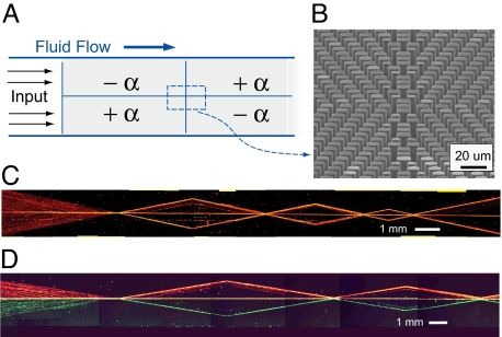
Of course, a dispersive −F element can be created if the order of the subelements in the +F element is flipped so that the +α element is placed above the −α element. Although the −F element is a mirror image of the +F element, its operation is not congruent. The element disperses supercritical particles into three distinct streams, two following the array angles ±α and one continuing along the interface, hydrodynamically trapped between the two birefringent elements—that is, they do not redisperse across the width of the original stream. In this sense, the focusing element is irreversible in its influence on particle trajectories, unlike an optical system. Fig. 6A shows a complex metamaterial device where several +F and −F elements have been connected in series with a refraction at each interface to form intricate particle handling modes. The paths traced out by the particles moving through the device demonstrate that objects can be repeatedly manipulated according to the functionality of the microfluidic metamaterial (Fig. 6B). Again, these complex trajectories were achieved in a single, straight microfluidic channel with one inlet and one outlet. The understanding of the dynamics of this structure are refined when two differently colored beads are used. Fig. 6C shows a similar device with separate inputs for each bead color. From this picture, it is clear that the beads “reflect” off the structure at the focus–defocus interface so there is little interaction between the top and bottom halves of the structure. Even along the centerline, it is rare for a green bead to cross over to the red side, and vice versa.
Fig. 6.
Complex microfluidic metamaterial. (A) Schematic of a complex metamaterial constructed by tiling several focusing, defocusing, and refractive elements. (B) Tilted, cross-sectional SEM image showing the interface between four subelements. (C) Collage of time-exposure images showing particle motion through a series of different +F and −F elements; motion is from left to right with just a single inlet and single outlet port. (D) A similar device with two separate inputs allowing two differently colored bead streams in the top and bottom halves of the device. Observe that particle crossover between the two halves of the device is rare; particles only mix when hydrodynamically trapped along the center reflection axis.
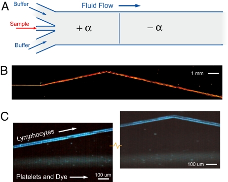
Steering streams of hard fluorescent microspheres by using these microfluidic metamaterial elements could be of great use in device design and for on-chip manipulation of functional beads; however, manipulating the trajectories of streams of live cells is also important (7). Next, we show that white blood cells can be refracted at an interface between two oppositely signed elements. Fig. 7A shows the formation a hydrodynamic jet with the more traditional three-input device: two inputs for running buffer and one for sample injection. In Fig. 7B, the sample inlet contains 2.7-μm red fluorescent beads that are immediately deflected along the array axis +α as they enter the first birefringent element. They continue along that trajectory until they reach the refracting interface between the +α and −α elements where they change direction. In this example, the length of the second element is longer than the first, so that the stream of beads crosses over its entry height and across any particles or fluid in the zigzag mode. Fig. 7C shows blood cells moving a similar device, now with larger spacing between the posts designed to separate and refract a stream of white blood cells. Lymphocyte cells with fluorescently stained nucleic acid (Hoechst) propagate in the bumping mode along the array axis, whereas blood platelets and residual labeling dye propagate in the zigzag mode. (Red blood cells and larger white blood cells where removed by Ficoll–Paque protocol before loading the chip.) Fig. 7C Left shows the separation of the initially mixed stream of lymphocytes from platelets and dye, and Fig. 7C Right shows the refraction of the lymphocytes and the interface between +α and −α elements. The time traces shown are for lymphocyte cells traveling at ≈300 μm/s with a 0.2-atm differential pressure, but velocities >1,000 μm/s were observed when using full suction pressures of ≈0.9 atm. The steering of biomaterial streams enables new compact device function to be incorporated within a single channel.
Fig. 7.
Beam steering for cells and particles. (A) Schematic of a traditional, three-input design for creating a laminar-flow hydrodynamic jet in a channel. The first element in the channel is a simple birefringence medium followed downstream by longer element with the same characteristics but having the opposite angle. (B) Wide angle composite image showing steering of a jet of 2.7-μm-diameter beads streaming through two microfluidic metamaterial elements and refracting, and the interface between them. Note that in the second longer element, the bead path crosses over the original input position. (C Left) A similar device designed to bump blood lymphocytes, but not blood platelets, was used to demonstrate refraction of a stream of cells (α = 11.3°, G = 8 μm, λ = 11 μm). Depicted is time exposure showing the separation of lymphocytes, which track along the array axis, and platelets and residual labeling dye that follow the fluid flow direction. (C Right) Refraction of lymphocytes at the interface between +α and −α array elements (see Movie S3). The flow of the platelets and dye is undisturbed.
Conclusions
We have reported on the design, construction, and use of complex microfluidic metamaterials: Post arrays skewed relative to the direction of fluid flow and assembled in various combinations that enable refraction of particle paths at interfaces and focusing of particles into jets. The elements provide a mechanism to direct streams of differently sized particles across laminar flows, enabling continuous flow, on-chip particle and cell handling. The realization of microfluid metamaterials demonstrates that complex objects paths can be implemented in a passive microfluidic platform with control reminiscent of modern-day optical designs, only with particles rather than light.
Methods
Microfluidic Metamaterial Fabrication and Device Operation.
The metamaterial post arrays, inlet/outlet microchannels, and reservoirs were fabricated in silicon wafers by using single-layer photolithography. Photomasks (Photosciences) were designed by using L-Edit (Tanner Research). Etching masks were formed on silicon wafers by using standard photolithography (SUSS MA6) with AZ 5214 photoresist (AZ Electronic Materials) and DI:MIF 312 (1:1) developer. Samples were deep-etched by using an ASE Multiplex tool (Surface Technology Systems) for deep reactive ion etching (DRIE) with an optimized recipe that ensured vertical side walls and low side-wall scalloping (100 nm peak to peak) as shown in Fig. 2D. Scanning electron microscopy (Zeiss LEO 1550 SEM) was used to characterize the etching recipes and measure array parameters such as post size, spacing, and gap. Through-wafer drilling (PrepStart; Danville Engineering) was used to create inlet holes. Devices were sealed with a thin layer of untreated PDMS film fixed to a glass coverslip backplane, allowing for repeated use of the same device. All devices were mounted in an acrylic jig connected to an external vacuum pump. Differential air pressure was used to control fluid flow through the chip. Pressure was varied in the range of 1–12 psi to achieve a wide range of flow speeds in the various devices from 50 to 500 μm/s. The running buffer for fluorescent microspheres (Duke Scientific) was degassed, ultrapure DI water containing 2 g/liter pluronic F108 (BASF).
Laser Fluorescence Microscopy.
An inverted microscope (Nikon TE2000) and a stereomicroscope (Nikon SMZ) were used to image the motion of fluorescent particles and cells in the metamaterial elements. High-pressure mercury lamps and an argon-ion laser were used as excitation sources with matching fluorescence filter sets. For laser fluorescence, the source was multiline (Spectra-Physics) with individual wavelength selection using an acoustic-optic tunable filter (AOTF; Neos Technologies). The laser spot was rapidly scanned with an x–y scanning mirror (Cambridge Technology) to create a wide, uniform illuminated field. Filter sets (Chroma Technology) were used for laser epifluorescent imaging of fluorescent beads and fluorescently labeled cells (488 nm, 568 nm excitation). Corresponding emission filters included green (525/50 nm, 605/50 nm, 565/50 nm, and dual bandpass filter 525/568 nm). Images were recorded by using a color Retiga 1300 CCD camera (QImaging) and a grayscale, IPentaMax ICCD camera (Princeton Instruments). Time exposures were acquired by both cameras as single images or sets of image files that were later compiled into video files. The color camera output refreshed to the screen after each integration, allowing video to be recorded by an AVI real-time screen capture program (AviScreen Classic, www.bobyte.com.) The intensified CCD camera output were stacks of sequential integrated images. All image processing was done with ImageJ (National Institutes of Health) and included merging grayscale images into red and green channels for RGB output and stack processing including multiple-frame sums or averaging.
Preparation of Blood Cells.
Venous, EDTA-anticoagulated blood (Oklahoma Blood Institute) was used as a source for platelets and lymphocyte white blood cells. The Ficoll–Paque (GE Healthcare) protocol was used to selecting lymphocytes and platelets from whole blood. After the centrifuge step, the lymphocyte- and platelet-rich layer was pipetted out and resuspended in running buffer (autoMACS; Miltenyi Biotech), a phosphate buffer with 150 mM NaCl at pH 7.2 containing 0.09% NaN3 and 0.2% BSA. The cells where then labeled with intercalating Hoechst dye (Sigma), using a 1:100 dye concentration so that residual dye could be used as flow tracer. Flowing dye and labeled platelets and lymphocytes were visualized with a color video camera, using Hg fluorescence microscopy at 365 nm with a 465/50-nm emission filter specific to the Hoechst label.
Supplementary Material
Acknowledgments.
We thank Cherry Ting (Hong Kong University of Science and Technology) for helpful discussions and preliminary experiments. This work was supported by the Air Force Office of Scientific Research, National Institutes of Health Grant HG01506, and National Science Foundation Nanobiology Technology Center Grant BSCECS9876771. It was also performed in part at the Cornell NanoScale Science and Technology Facility, which is supported by the National Science Foundation under Grant ECS-9731293, its users, Cornell University, and Industrial Affiliates.
Footnotes
The authors declare no conflict of interest.
This article contains supporting information online at www.pnas.org/cgi/content/full/0712398105/DCSupplemental.
References
- 1.Newton I. Walford, London: 1704. Opticks or a Treatise of the Reflections, Refractions, Inflections and Colours of Light. [Google Scholar]
- 2.Squires TM, Quake SR. Microfluidics: Fluid physics at the nanoliter scale. Rev Mod Phys. 2005;77:977–1026. [Google Scholar]
- 3.Atencia J, Beebe DJ. Controlled microfluidic interfaces. Nature. 2005;437:648–655. doi: 10.1038/nature04163. [DOI] [PubMed] [Google Scholar]
- 4.Huang LR, Cox EC, Austin RH, Sturm JC. Continuous particle separation through deterministic lateral displacement. Science. 2004;304:987–990. doi: 10.1126/science.1094567. [DOI] [PubMed] [Google Scholar]
- 5.Saleh BEA, Teich MC. Fundamentals of Photonics. New York: Wiley; 1991. [Google Scholar]
- 6.Inglis DW, Davis JA, Austin RH, Sturm JC. Critical particle size for fractionation by deterministic lateral displacement. Lab Chip. 2006;6:655–658. doi: 10.1039/b515371a. [DOI] [PubMed] [Google Scholar]
- 7.Davis JA, et al. Deterministic hydrodynamics: Taking blood apart. Proc Natl Acad Sci USA. 2006;103:14779–14784. doi: 10.1073/pnas.0605967103. [DOI] [PMC free article] [PubMed] [Google Scholar]
- 8.Editorial. Not just a light story. Nat Mater. 2006;5:755. doi: 10.1038/nmat1749. [DOI] [PubMed] [Google Scholar]
- 9.Walser RM. Electromagnetic metamaterials. Proc SPIE. 2001;4467:1–15. [Google Scholar]
- 10.Shelby RA, Smith DR, Schultz S. Experimental verification of a negative index of refraction. Science. 2001;292:77–79. doi: 10.1126/science.1058847. [DOI] [PubMed] [Google Scholar]
- 11.McLeod JH. The axicon: A new type of optical element. J Opt Soc Am. 1954;44:592–597. [Google Scholar]
- 12.Durnin J, Miceli JJ, Jr, Eberly JH. Diffraction-free beams. Phys Rev Lett. 1987;58:1499–1501. doi: 10.1103/PhysRevLett.58.1499. [DOI] [PubMed] [Google Scholar]
- 13.Nagrath S, et al. Isolation of rare circulating tumour cells in cancer patients by microchip technology. Nature. 2007;2450:1235–1239. doi: 10.1038/nature06385. [DOI] [PMC free article] [PubMed] [Google Scholar]
- 14.Knight JB, Vishwanath A, Brody JP, Austin RH. Hydrodynamic focusing on a silicon chip: Mixing nanoliters in microseconds. Phys Rev Lett. 1998;80:3863–3866. [Google Scholar]
- 15.Huang LR, et al. Generation of large-area tunable uniform electric fields in microfluid arrays for rapid DNA separation. Tech Dig Int Electron Devices Meet. 2001:363–366. [Google Scholar]
- 16.Di Carlo D, Irimia D, Tompkins RG, Toner M. Continuous inertial focusing, ordering, and separation of particles in microchannels. Proc Natl Acad Sci USA. 2007;104:18892–18897. doi: 10.1073/pnas.0704958104. [DOI] [PMC free article] [PubMed] [Google Scholar]
Associated Data
This section collects any data citations, data availability statements, or supplementary materials included in this article.


