Abstract
We developed and investigated a scanning sampled measurement (SSM) technique for scatter measurement and correction in cone beam breast CT imaging. A cylindrical polypropylene phantom (water equivalent) was mounted on a rotating table in a stationary gantry experimental cone beam breast CT imaging system. A 2-D array of lead beads, with the beads set apart about ~1 cm from each other and slightly tilted vertically, was placed between the object and x-ray source. A series of projection images were acquired as the phantom is rotated 1 degree per projection view and the lead beads array shifted vertically from one projection view to the next. A series of lead bars were also placed at the phantom edge to produce better scatter estimation across the phantom edges. Image signals in the lead beads/bars shadow were used to obtain sampled scatter measurements which were then interpolated to form an estimated scatter distribution across the projection images. The image data behind the lead bead/bar shadows were restored by interpolating image data from two adjacent projection views to form beam-block free projection images. The estimated scatter distribution was then subtracted from the corresponding restored projection image to obtain the scatter removed projection images.
Our preliminary experiment has demonstrated that it is feasible to implement SSM technique for scatter estimation and correction for cone beam breast CT imaging. Scatter correction was successfully performed on all projection images using scatter distribution interpolated from SSM and restored projection image data. The resultant scatter corrected projection image data resulted in elevated CT number and largely reduced the cupping effects.
Keywords: Cone beam breast CT, scattered radiation, cupping effect, flat-panel detector, scatter-to-primary ratio
1. INTRODUCTION
One of the major issues in constructing a flat-panel based cone beam CT (CBCT) system is the lack of scatter rejection capability during the scanning and image acquisition process. As an area detector, the flat-panel detector would receive a larger amount of scattered x-rays as compared to the detector systems used in conventional fan beam CT. Scattered radiation, as part of the detected image signal, tends to degrade and bias the projection as well as reconstructed CT images. This effect results in decreased contrast sensitivity, inaccuracy of CT numbers, and a cupping effect with which CT numbers near the rotating center tend to be lower.[1–6] The effect of scattered radiation on the projection image data depends strongly on the x-ray technique settings, imaging geometry as well as the object under study. Due to the use of an area detector in cone beam CT, the amount of scatter generated is much higher than that in conventional fan beam based CT. Without scatter rejection, the scatter-to-primary ratio (SPR) could easily exceed 100% with large cone beam angles and object size. Thus the development and use of scatter rejection or correction technique is essential for successful cone beam CT reconstruction. Scatter reduction or correction would help produce more accurate CT image data for improved image contrast and enable quantitative image analysis.
Various techniques have been proposed and investigated to reduce, remove or correct for scatter in cone beam projection image data and improve the accuracy of CT reconstruction. These methods include air gap, anti-scatter grid, beam stop, Monte Carlo (MC) simulation and convolution (mathematical) approaches.[7–12] Both air gap and anti-scatter grid have produced noticeable improvement only in low resolution CT images but at the expense of higher patient dose. The traditional beam stop approach requires two scans of projection image views (one with array of beam stops to estimate scatter distribution and the other without array of beam stops to obtain the primary plus scatter images) which potentially increases radiation dose to the patients and data acquisition time. The Monte Carlo simulation and convolution methods are based on analytical models and can be very complicated and time consuming. Moreover, modeling scatter radiation with the convolution method may not provide accurate estimation because scatter distribution does not depend only on the transmitted x-ray image data but also on the composition and distribution of the scattering materials.
We have developed a scanning sampled measurement (SSM) technique for scatter measurement and correction in cone beam breast CT imaging. The method requires only one scan to acquire both the projection image data and sampled scatter measurements which can be interpolated into scatter distribution for image correction. Based on the SSM technique, scatter free projection image data can be obtained for accurate cone beam CT reconstruction. Preliminary results are presented to demonstrate the feasibility of the SSM technique for scatter correction in CBCT imaging. Measurements of the SPR in the projection images and contrast in the reconstructed CBCT images are also presented to demonstrate the SSM technique.
2. METHODS AND MATERIALS
2.1 Experimental setup
A prototype cone beam breast CT scanner was constructed and mounted on a 4′ × 8′ optical bench with air suspensions to maintain the proper leveling and minimize the vibration error during the image acquisition. The system consists of a three phase, high frequency generator (INDICO 100, CPI Canada Inc., Ontario, Canada) coupled with a dual-focal spot x-ray tube (G1592, Varian Medical Systems, Salt Lake City, UT). An a-Si:H/CsI:Tl based plat-panel detector (Paxscan 4030CB, Varian Medical Systems, Salt Lake City, UT) was employed to acquire cone beam CT projection images. A thick layer of CsI(Tl) is directly deposited on top of the a-Si:H circuitry and convert absorbed x-ray photons into visible light. The detector has an active area of 39.7 cm × 29.8 cm (15.6 in. × 11.7 in.) and a native pixel pitch of 194 μm. The active area of the detector is divided into a 2048 × 1536 array of image elements, each of which consists of a photodiode converting visible light into charges. In this study, the detector was operated at 2 × 2 binning mode which resulted in an imaging matrix size of 1024 × 768 with effective pixel size of 388 μm. Image signals were digitized into 14-bit data and transferred from detector to command processor through high speed optical link. CBCT projection images were then transferred to an acquisition computer via a high speed video frame grabber (Road Runner R3, BitFlow, Inc., Woburn, MA). The acquisition computer has a Pentium 4 CPU running at 3.2 GHz with 4 GB RAMs installed for storing acquired projection image data.
A motorized rotating table was mounted on the optical bench and to hold the phantom or breast specimen. A 3 mm thick Lucite plate with a 2-D array of lead beads attached was mounted on a motorized translational stage and placed between the object and x-ray source. The array of lead beads, with each bead measured 1.5 mm in diameter, and placed at about 10.5 mm (7 times of bead diameter) apart from each other, was computer controlled and moved vertically. A series of lead bars of 2 mm thick and 1.5 mm wide were horizontally interlaced with 2-D array of lead beads at the edge of the phantom to cover the phantom edge and produce better scatter estimation across the phantom edges. Motions of the phantom and array of lead beads/bars were computer controlled and synchronized to x-ray pulses and image acquisition. The experimental setup for scattered radiation measurement in CBCT is illustrated in Figures 1 and 2, respectively.
Figure 1.
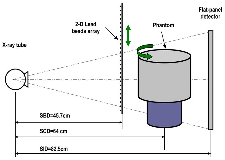
Experimental setup for scattered radiation measurement using scanning sampled measurement (SSM) technique in cone beam breast CT.
Figure 2.
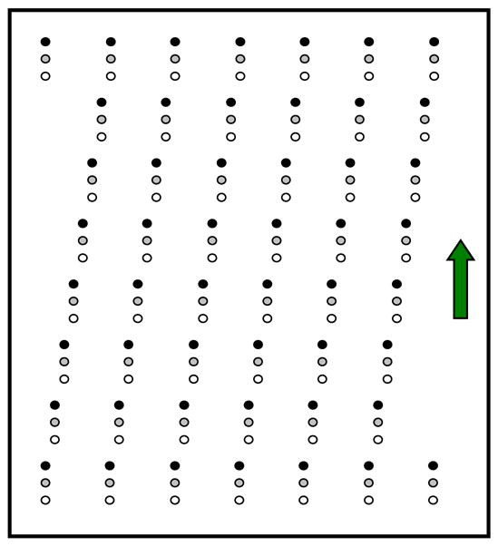
A 2-D array of lead beads used to estimate scatter distribution in cone beam breast CT imaging. The array of beads was tilted vertically.
2.2 CBCT image acquisition
A cylindrical polypropylene phantom of 15 cm in diameter was mounted on the rotating table and imaged for the imaging experiments. The attenuation property of the polypropylene phantom is similar to that of water. The magnification of the array of lead beads was by a factor of about 1.8 on the detector surface, resulted in a circular shadow of about 7 pixels in diameter in the projection images. The 2-D array of lead beads was slight tilted in such a way that adjacent beads in the same column were shifted left or right by one bead while adjacent beads in the same row were shifted up or down by one bead. This way, when the bead array will have to be moved vertically by the length of 49 beads before the bead shadows, where sampled scatter measurement are made, advance to the original locations of the bead shadows. Thus, the array may be moved in such a way to allow each detector pixel to be blocked by the lead bead only in a small fraction of projection views (e.g. one every 49 consecutive views). This would also help minimize the ghost effect.
A series of projection images were acquired as the phantom was rotated at a rate of 1 degree per view and the array of lead beads shifted by 3 mm (2 times of lead bead size) vertically from one projection view to the next. The array of lead beads was controlled to move 24 steps downward then reversely move 24 steps upward, and this moving pattern was repeated as the phantom rotated throughout the image acquisition. Each detector pixel will be blocked by the lead bead once every 24 views. Projection images were acquired at 85 kVp and 20 mA with 10 mSec x-ray pulses, resulting in an exposure of 0.2 mAs per projection image. Small focal spot (0.6 mm) mode was selected to minimize the focal spot blurring during the image acquisition.
Image signals in the lead beads/bars shadow were used to obtain sampled scatter measurements which were then interpolated using 2-D spline algorithm to form an estimated scatter distribution across the projection images for each projection view. Meanwhile, the image data behind the lead bead shadows were restored by interpolating image data from two adjacent projection views to form beam-block free projection views. The estimated scatter distribution was then subtracted from the corresponding restored projection view to obtain the scatter-free projection image. Linear image data were used in these measurements and estimations. The dark current and gain corrections were applied to the data prior to image processing. The final scatter-free projection images were then used for CBCT reconstruction. The schematic diagram of the scatter removal algorithm to suppress scattered radiation in CBCT breast imaging is illustrated in Figure 3.
Figure 3.

Schematic diagram of scatter removal algorithm to suppress scattered radiation in CBCT breast imaging.
Assume that 2-D scatter distribution estimated from the sampled scatter is IS, and the beam-block free projection image data is IP+S, the scatter-free projection image (primary only) can be computed as follows:
| (1) |
Following the measurement of IS(x,y), IP+S(x,y), and IP(x,y), the position dependent scatter-to-primary ratio, SPR(x,y), which is often used to quantify the presence of scattered radiation, can be computed as follows:
| (2) |
To demonstrate the effect of scatter removal on CBCT images, beam-block free projection data of the cylindrical polypropylene phantom were also reconstructed the CBCT images prior to the scatter removal and the CT images were compared with that with scatter correction.
3. RESULTS AND DISCUSSION
The total image signal IP+S, primary intensity (scatter free) IP, and scatter component IS for cylindrical polypropylene phantom in horizontal direction were shown in Figure 4. As observed, the scatter component remains largely uniform inside the phantom but tends to decrease towards the central axis of the phantom. The scatter-to-primary ratio was computed and plotted in Figure 5 in horizontal direction. The SPR reaches the highest at the center of the phantom and gradually decreases toward the edge of the phantom. The SPRs in the projection images of a cylindrical polypropylene phantom are found to range from 0.12 to 1.0 in this study.
Figure 4.
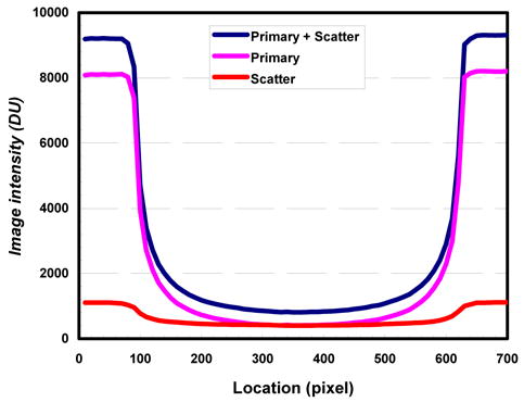
Image intensity plotted across polypropylene phantom. Scatter distribution estimated from a 2-D array of lead beads/bars using SSM technique.
Figure 5.
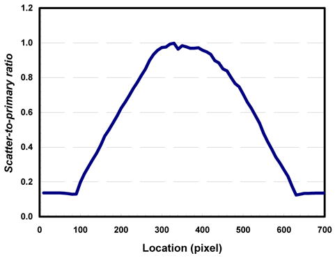
Scatter-to-primary ratio measured and plotted across polypropylene phantom.
Slices of CBCT images of the cylindrical polypropylene phantom with and without scatter correction were shown in Figures 6 and 7, respectively. As observed, the image in Figure 6 demonstrated largely uniform CT numbers within the phantom as compare to that of Figure 7. The cupping effect was largely eliminated when the scatter was corrected using the SSM technique while the cupping effect was clearly shown in Figure 7. To quantify the effectiveness of scatter correction, the CT number profile across the phantom image obtained with scatter correction was plotted and compared with that across the phantom image obtained without correction in Figure 8. Figure 8 shows that in the image obtained without correction, the CT numbers dropped by about 220 from the edge to the center of the phantom. The CT numbers at the edge were lower than the normal value as well. With scatter correction, the CT numbers were restored to higher values. The values are largely uniform and the cupping effects are largely eliminated.
Figure 6.
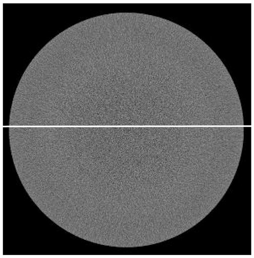
Cone beam CT images of a polypropylene phantom with scatter corrected. Cupping effect is largely eliminated.
Figure 7.
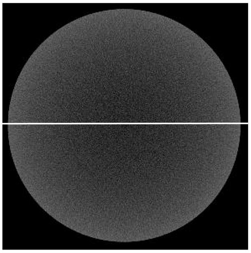
Cone beam CT images of a polypropylene phantom without scatter corrected. Cupping effect is clearly shown.
Figure 8.
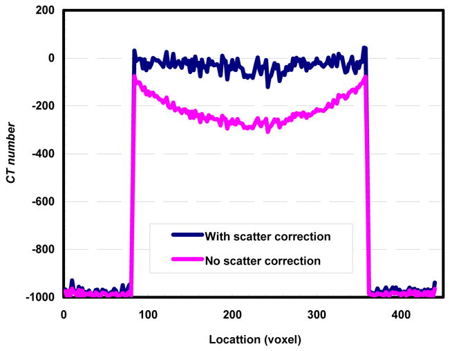
Cone beam CT image signal profile vs. location for images reconstructed with and without scatter correction.
4. CONCLUSION
A scanning sampled measurement (SSM) technique was introduced and demonstrated to estimate and correct for scatter component in cone beam CT projection image data. Our preliminary experiment has demonstrated that it is feasible to implement SSM technique for scatter estimation and correction for cone beam breast CT imaging. Scatter correction was successfully performed on all projection images using scatter distribution interpolated from SSM and restored projection image data. Scatter correction has resulted in elevated, more accurate CT numbers and largely eliminated the cupping effect in cone beam CT reconstruction.
Acknowledgments
This work is supported in part by a research grant EB000117 from the National Institute of Biomedical Imaging & Bioengineering and a research grant CA104759 from the National Cancer Institute.
References
- 1.Endo M, Tsunoo T, Nakamori N, Yoshida K. Effect of scattered radiation on image noise in cone beam CT. Med Phys. 2001;28:469–474. doi: 10.1118/1.1357457. [DOI] [PubMed] [Google Scholar]
- 2.Siewerdsen JH, Jaffray DA. Cone-beam computed tomography with a flat-panel imager: Magnitude and effects of x-ray scatter. Med Phys. 2001;28:220–231. doi: 10.1118/1.1339879. [DOI] [PubMed] [Google Scholar]
- 3.Johns PC, Yaffe M. Scattered radiation in fan beam imaging systems. Med Phys. 1982;9:231–239. doi: 10.1118/1.595076. [DOI] [PubMed] [Google Scholar]
- 4.Glover GH. Compton scatter effects in CT reconstructions. Med Phys. 1982;9:860–867. doi: 10.1118/1.595197. [DOI] [PubMed] [Google Scholar]
- 5.Joseph PM, Spital RD. The effects of scatter in x-ray computed tomography. Med Phys. 1982;9:464–472. doi: 10.1118/1.595111. [DOI] [PubMed] [Google Scholar]
- 6.Kanamori H, Nakamori N, Inoue K, Takenaka E. Effects of scattered x-rays on CT images. Phys Med Biol. 1985;30:239–249. doi: 10.1088/0031-9155/30/3/004. [DOI] [PubMed] [Google Scholar]
- 7.Kalendar W. Monte Carlo calculations of x-ray scatter data for diagnostic radiology. Phys Med Biol. 1981;26:835–849. doi: 10.1088/0031-9155/26/5/003. [DOI] [PubMed] [Google Scholar]
- 8.Chan HP, Doi K. Physical characteristics of scattered radiation in diagnostic radiology: Monte Carlo studies. Med Phys. 1985;12:152–165. doi: 10.1118/1.595771. [DOI] [PubMed] [Google Scholar]
- 9.Boone JM, Seibert JA. An analytical model of the scattered radiation distribution in diagnostic radiology. Med Phys. 1988;15:721–725. doi: 10.1118/1.596186. [DOI] [PubMed] [Google Scholar]
- 10.Honda M, Kikuchi K, Komatsu K. Method for estimating the intensity of scattered radiation using a scatter generation model. Med Phys. 1991;18:219–226. doi: 10.1118/1.596710. [DOI] [PubMed] [Google Scholar]
- 11.Ohnesorge B, Flohr T, Klingenbeck-Regn K. Efficient object scatter correction algorithm for third and fourth generation CT scanners. Eur J Radiol. 1999;9:563–569. doi: 10.1007/s003300050710. [DOI] [PubMed] [Google Scholar]
- 12.Hsieh J. Image artifacts: Causes and correction. In: Goldman LW, Fowlkes JB, editors. Medical CT and Ultrasound: Current Technology and Applications, Proc Of the 1995 Summer School of the AAPM. Chap 26. Advanced Medical Publishing; Madison, WI: 1995. pp. 487–518. [Google Scholar]


