

Abstract
Single molecule tracking is widely used to monitor the change in position of lipids and proteins in living cells. In many experiments in which molecules are tagged with a single or small number of fluorophores, the signal/noise ratio may be limiting, the number of molecules is not known, and fluorophore blinking and photobleaching can occur. All these factors make accurate tracking over long trajectories difficult and hence there is still a pressing need to develop better algorithms to extract the maximum information from a sequence of fluorescence images. We describe here a Bayesian-based inference approach, based on a trans-dimensional sequential Monte Carlo method that utilizes both the spatial and temporal information present in the image sequences. We show, using model data, where the real trajectory of the molecule is known, that our method allows accurate tracking of molecules over long trajectories even with low signal/noise ratio and in the presence of fluorescence blinking and photobleaching. The method is then applied to real experimental data.
INTRODUCTION
Using fluorescence microscopy with single-molecule sensitivity, it is now possible to follow to movement of individual fluorophore tagged molecules such as proteins and lipids in the cell membrane with nanometer precision (1–3). Using single molecule tracking, diffusion or directed motion of molecules on the cell can be investigated to elucidate the structure of the cell membrane. To date, most methods have been based on nonlinear least-square fitting of the fluorescence images to Gaussian functions and while automated tracking algorithms exist, quite often manual input is necessary (4,5). The number of molecules has to be known and most software cannot handle the appearance of additional objects during tracking. This frequently happens when the density of molecules is high at the beginning of the image sequence so that they are initially so close together that they cannot be resolved separately and later move apart (6). Another problem is that due to low signal/noise ratio, some molecules cannot be detected in individual frames so that longer tracks are split into shorter sections. Long trajectories are usually needed to get good statistics for diffusion analysis whereas the typical observation time of the fluorophore, before irreversible photobleaching occurs, sets a limit to the length of trajectories. Furthermore deterministic methods, where no randomness is assumed, detect spots with regional maxima (7). They usually require us to set a threshold and the detection is very sensitive to this threshold setting. For experimental data, the correct threshold is usually not known. To be computationally efficient, a well-known deterministic method selects the threshold at the upper 30th percentile of brightness for the entire image (8). However, the threshold-based method may fail to detect real spots which are less bright than the threshold. Also, most algorithms for single molecule tracking focus only on fitting of spatial information (9–11). Since we are processing a set of sequential images, we have used both temporal and spatial information. Specifically we have used a Bayesian-based approach, which uses prior information in time and space about the molecule trajectory and does not require a strict threshold.
The tracking of single dye-conjugated molecules is a multitarget tracking problem with each target a fluorescent signal. We have developed a sequential Monte Carlo (SMC) algorithm which considers spatial and temporal information of the molecular motion since this gives longer and more accurate tracks. The SMC algorithm can also track several molecules simultaneously. However, the number of molecules is not known, a priori, since the number of targets may be different in each frame. To cope with the unknown number of targets, we have used trans-dimensional SMC where the number of dimensions can change with time. We also require parameter association for this trans-dimensional SMC method to identify the correct molecules in each frame. In this article, we solve the parameter association problem by clustering parameters using expectation maximization (EM) algorithm. Each target for tracking via our SMC method is represented by a Gaussian profile with unknown center coordinate, amplitude, and width (12–14). The proposed algorithm based on the track-before-detection (TBD) scheme uses original data (15,16). Therefore, we can avoid the information loss which may happen in the threshold-based detection algorithm (8,17). In case of low signal/noise ratio (SNR), our modified SMC algorithm with TBD scheme may detect weak signals.
The remainder of the article is organized as follows. The Theory section gives the philosophy of the Bayesian inference as used in this article. The Sequential Monte Carlo (SMC) section introduces the Bayesian sequential estimation framework, which leads to a particular trans-dimensional SMC approach. The Fluorescence Image section discusses the modeling assumptions such as prior information for the single molecule fluorescence images. The main algorithms for the trans-dimensional SMC tracking of the objects on the single molecule fluorescence images are presented in the Algorithm section. This section focuses on three points: how to generate the proposal function based on the image itself; how to decide the dimension; and how to associate parameters among particles. In the Results section, our proposed method is evaluated with the synthetic and real experimental data sets and with the results obtained using Crocker's well-known deterministic approach (8). We then discuss possible future work and make concluding remarks.
THEORY
Bayesian inference and Monte Carlo
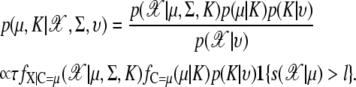
Bayesian inference (18,19) provides a logical framework for assessing the existing state of knowledge and then refining this on the basis of new experimental data. It is a learning system that tests the degree to which a model or hypothesis is consistent with the experimental data and any prior knowledge available about the problem. Consequently, it is to some extent dependent on a reasonable choice for this prior knowledge. It refines a model M in the light of the experimental data D, starting from a set of prior assumptions C. The first step is to define a conditional prior probability p(M|C), that is to say, the probability that the model M is correct, given only the initial assumptions. The next stage updates p(M|C) in response to the experimental data (D) to give the posterior probability p(M|D, C). To do this, it makes use of Bayes' theorem:
 |
(1) |
For this rule to be applicable, it must be possible to define the probability p(D|M, C) (the likelihood) that the experimental images D are consistent with the model M and the prior assumptions C. Samples from this posterior probability can be collected by Monte Carlo algorithm. In most applications, it is not feasible directly to generate independent samples from the distribution p(M|D, C). In this case, a user-defined trial distribution q(·), which is different from p(M|D, C), is used to generate the samples. Rejection method (20), importance sampling (21,22), and sampling-importance-resampling (SIR) (23) are well studied to generate the samples from q(·). In this article, we use the SIR scheme for sampling.
METHODS
Sequential Monte Carlo (SMC)
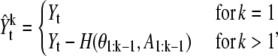
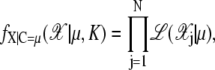
We describe a Bayesian sequential estimation framework for multitarget tracking, i.e., the sequential Monte Carlo (SMC) algorithm (24–26). We describe the general framework for a dynamic model with the state space θt and observation space Yt, respectively, where t denotes the discrete time index. The distribution of interest for tracking is the posterior, p(θt|Y1:t), where Y1:t is a shorthand notation for (Y1, ···, Yt). In the Bayesian sequential estimation framework, the posterior distribution is obtained by the two-step recursion, as follows.
Prediction step,
 |
(2) |
Filtering step,
 |
(3) |
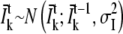
This recursion requires the specification of two models; a dynamic update model for the hidden states p(θt|θt–1) and a model for the state likelihood given the current measurement p(Yt|θt). The recursion is initialized with some distribution for the initial state p(θ0). The dynamic update and likelihood models are given by
 |
(4) |
where Ft and Gt can be regarded as either nonlinear or linear functions corrupted by noise, Ut and Vt at time t.
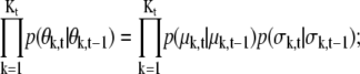
In our application of interest, the number of dimensions is unknown and hence we need a trans-dimensional approach which estimates the number of dimensions (27,28). Let { denote a random measure that characterizes the posterior distribution p(θ0:t, K0:t|Y1:t), where {
 n = 0, ···, N} is a set of hidden variables with associated weights
  θ0:t and
  are the sets of all states and the dimensions of the nth sample, respectively. Applying a sequential importance sampling and resampling scheme to Eqs. 2 and 3, we can obtain a generic particle filter (25). For the sake of simplification, wt is expressed instead of
  where
where  as
as
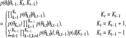
 |
(5) |
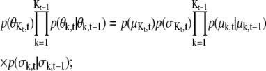
where s is the scaling factor to avoid a numerical problem in the likelihood. The prior distribution of θt is given by
 |
(6) |
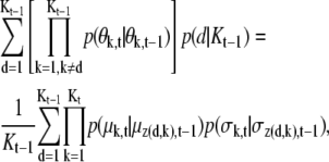
where, in the case of Kt < Kt–1,  and d is the index for the spot to be deleted.
Fluorescence image
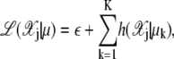
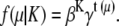
Single molecule fluorescence images may be represented by particular profiles such as Gaussian profiles for spot shapes. Only four parameter elements are required to define a Gaussian profile: the x and y position, amplitude, and width. Each frame of a sequence of fluorescence images is represented by an intensity function I(x) at time t as
 |
(7) |
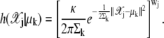
where Ak is the amplitude of each spot and φk(x;μk, σk) denotes the radial function of x with a Gaussian profile which consists of two components, center position μk and width of the spot, σk as
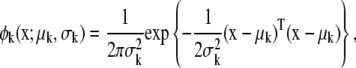 |
(8) |
with x = [x1, x2]T and μk = [μk, 1, μk, 2]T representing coordinate positions. The quantity εe(x) in Eq. 7 is assumed to be white noise with mean μe and variance  i.e., εe(x) ∼ N(εe(x);μe,
  In practice, Eq. 7 may be written in the linear model framework:
 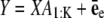 where
where 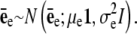 Here, 1 and I denote a vector with value 1 and the identity matrix, respectively, and
  is a vector for amplitudes of spots. Y is built from Eq. 7 by assembling all intensities I(x) into a vector and X is defined by
  where Xk is a vector made up from the image profile of the kth spot. Denoted by θk ∈ Θk, the parameter vector associated with the model indexed by k ∈ κ. Now, the priors are defined as
 |
(9) |
where k = 1, 2, …, K and K ∈ {0, 1, …, K max}. T1 and T2 are the size of an image and N, U, and Ga stand for the normal, uniform, and γ-distributions, respectively. The values α and β are assumed to be known and μe and σe are estimated during the simulation. For the synthetic example in this article, μA and σA are fixed. The nuisance parameter A1:K may be removed in the SMC estimation by linear analytical integration (Rao-Blackwellization) (29).
Marginal likelihood
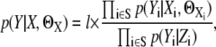
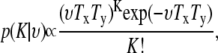
Marginalizing A1:K, the likelihood is defined as
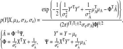 |
However, this marginal likelihood still requires very heavy computation since Y is a big quantified vector even though we are updating only a small number of spots. We can reduce the time complexity of computation using an approximation with the following steps. We introduce an auxiliary image Z and each pixel of the auxiliary image is set to be μZ where it is obtained by the mean of the global background. If the region occupied by the spots of interest is relatively small compared to the whole region in each frame, we can obtain 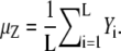 We can calculate the likelihood for image Z using
 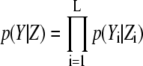 from
from  where
where 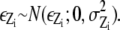 We then divide the image into two regions, S and Sc where S has the interesting spots. Sc is the noninteresting region and it is regarded as background with only noise. Now, we redefine the likelihood
 |
(10) |
where 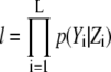 and L is the number of pixels in the image. Note that l is calculated once in each frame so that we can reduce the time complexity. The values ΘX and S denote (μA, σA, σe) and the region in which Gaussian profiles of X appear, respectively.
Prior probability
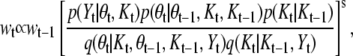
There are two terms for the prior information, p(θt|θt–1, Kt, Kt–1) and p(Kt|Kt–1). In the prior information for Kt given Kt–1, it is assumed that each target is independent of all others and the distribution is assumed uniform distribution. That is, p(Kt|Kt–1) = 1/Kmax. The density for parameters p(θt|θt–1, Kt, Kt–1) is divided into three different forms, as in Eq. 6.
For Kt = Kt–1,
 |
(11) |
for Kt = Kt–1 + 1,
 |
(12) |
and for Kt = Kt–1 – 1,
 |
(13) |
where z(d, k) is an index function and if k < d, z(d, k) = k otherwise, z(d, k) = k + 1. The partial terms in the above equations are defined as
 |
(14) |
where Yt is a Tx × Ty image. Here, p(σk,t|σk,t–1) is a random walk with mean σk,t–1 and variance Σσ where the mean of the width μσ and the variance of the width Σσ are assumed to be known hyperparameters for mean and variance of size of width. We set μσ = 1.5 and Σσ = 0.01 in this article.
Algorithm
Before applying the sequential Monte Carlo method, it is important to remove background noise which may lie in particular regions. In the real experimental image, this background noise is very hard to detect and subtract so we use a very simple approach which subtracts the average values in the given area for each pixel of the image. That is, we average the intensities of the M closest pixels around the pixel of interest. The calculated value is subtracted as a background noise for the pixel. This is a so-called the local mean removal procedure (30). Afterwards, we use a trans-dimensional sequential Monte Carlo method which has three types of proposal functions: Dimension Invariant, Birth, and Death. We set Kt = Kt–1 for the Dimension Invariant. For other proposals, the difference between the dimensions between previous and current steps is limited to one. That is, Kt = Kt–1 + 1 in the Birth move and Kt = Kt–1 – 1 for the Death move, respectively.
Proposal functions
Proposal functions q have two forms. One is the kernel function for dimension, q(Kt|Kt–1, Yt). The other is the proposal function for parameters, q(θt|θt–1, Kt, Kt–1, Yt). Here, the proposal function for Kt is designed to be the same as the prior function, p(Kt|Kt–1). However, the proposal function for parameters is designed by dealing with information of the images directly. To make a good proposal function, we factorize the function q(θt|θt–1, Kt, Kt–1, Yt) = p(θt, d|θt–1, Kt, Kt–1, Yt) into the three different forms, as follows. Dimension invariant,
 |
(15) |
Birth move,
 |
(16) |
Death move,
 |
(17) |
Here, note that  is different from the original image, Yt. The
  is generated from the original image by subtracting an image which is reconstructed with k – 1 previous proposed spots.
 |
(18) |
where A1:k–1 stands for the vector of amplitudes of the spots and H(·, ·) denotes the reconstruction function to generate an ideal image with i – 1 spots. Since the equation has the recurrence form, we can rewrite it as
 |
(19) |
We can reduce the required time complexity through the use of this recurrence form. We have many functions in Eqs. 15–17,
 |
We introduce two further functions, Q1 and Q2. The first proposal function, Q1 is used to generate samples for a new spot in the birth move. We obtain a corresponding vector by transforming a two dimensional image  From the TxTy × 1 vector, we reconstruct a cumulative density function (CDF). Now, we can sample the position of a new spot from the inverse probability density function given the CDF. The brief algorithm for the Q1 function is as follows:
Algorithm 1: Q1 function
Let yL be the Tx × Ty image

yL is transformed to be a vector.
Make a cumulative density function (CDF) from the vector.
Generate a random number, u. That is, u ∼ U(u;0, 1).
Propose a position from the inverse probability density function using the CDF.
Unlike the Q1 function, the second proposal function Q2 is used to update the locations of the existing spots. Thus, the Q2 function has one more input, μk′, t–1 which is the location of the kth spot in the previous image. Since we know the potential area to be updated and searched for the spot in the next time step, we do not have to search for the next position in the whole area as the Q1 function does. This speeds up the algorithms by reducing the time complexity. First of all, we extract an m × n size subimage centered at μk′, t–1 in Yt. All elements of the subimage are divided by the total sum of the elements of the image to make a normalized image. We call this normalized image yL where  We also introduce a m × n size normalized user defined Gaussian Kernel, yprior, where
  We obtain ypost by simply multiplying yL and yprior,
 |
(20) |
where ⊗ denotes the elementary multiplication operation. The explanation of the algorithm for Q2 is shown in Algorithm 2.
Algorithm 2: Q2 function
Extract an m × n subimage centered at μk, t–1 in

Normalize the extracted subimage and name it as yL where

Introduce yprior where yprior is a m × n size normalized Gaussian kernel.
Calculate ypost in Eq. 20 and normalize it.
Propose the position from an inverse probability density function using the normalized ypost as in steps 2–5 in Algorithm 1.
Note that Q1 and Q2 functions follow the Bayesian scheme by using prior information. Since there is no prior information for location in Q1, the proposal function is based only on the image. By comparison, the second function Q2 has the previous position which is used for prior information. Thus, we can use posterior and prior information from the image directly. The probability of q(d|θt–1, Kt–1, Yt) for dimension invariant and birth move simply becomes  However, in the Death move, this equation may be designed more carefully. To obtain this probability, we use a p-value for significance and first-order Markov random field (MRF). That is, the MRF prior probability of the subimage based on the previous position for a spot is compared with that of a finite number of randomly permuted images. Before explaining the algorithm in detail, we present MRF prior probability π(·) of a particular image. Let y be a particular M × N image. Since
  where y–i means a set of all elements except the ith element in y, we instead use a pseudo-prior probability for π(·),
 |
(21) |
where i ∼ j denotes that jth element is a neighbor of the ith element in the image and τ is a parameter for normalization.
Returning to the algorithm to select a spot for deletion, we extract a m × n subimage yorigin from Yt. The extracted image yorigin is permuted randomly η times so that we obtain η permuted images  With η + 1 images including yorigin, we obtain π(yorigin) and
  We calculate how many permuted images have higher MRF prior probability than the original image yorigin. The calculated count for each spot is used to build the probability, q(d|θt–1, Kt–1, Yt). The brief algorithm for q(d|θt–1, Kt–1, Yt) is described in Algorithm 3.
Algorithm 3: q(d|θt–1, Kt–1, Yt) for Death move
for i = 1 to Kt–1 do
Extract an m × n subimage, yorigin, centered at μi,t–1 from Yt.
Calculate π(yorigin) in Eq. 21.
count = 0.
for j = 1 to η do
Permute the yorigin randomly and make

Calculate
 in Eq. 21.
end for
if
 then
thencount = count + 1.
end if
Obtain p-values for significance of ith spots. PV(i) = count.
end for
d ∼ q(d|θt–1, Kt–1, Yt)
Resampling
We use a resampling method to reduce the degeneracy phenomena since only a small number of samples dominate the weights after a few iterations in time. Generally this problem is solved by generating a new set of  by resampling Ns times from the approximation of p(θt|Y1:t) and the weight of the resampled sample is reset to
  (31). In this article, we use a modified resampling method since our sequential Monte Carlo addresses a dimension variable problem. A sample may have spots for both real molecules (targets) and incorrectly identified molecules (false alarms). For example, suppose that we have a sample with three spots. Assume that two spots indicate targets but the other spot is a false alarm. In this case, the typical resampling approach cannot remove the false spot since they are jointly resampled. Therefore, we modified the conventional resampling scheme with the following three steps. First, we divide the nth sample
  with k spots into k samples with only one spot. The same weights as
  is assigned to the k separated samples. Next, we resample the divided samples by the typical resampling method (31). Finally, we recombine samples to make dimension variable samples under a discrete probability density function.
Estimating parameters
The parameters of all samples in each time are estimated by clustering algorithms. We use an EM algorithm which clusters samples with given weights wt. Since we have approximated the value,  for the number of clusters, we will do several EM clustering algorithms for
  where
where  There are two types of observations: spot information and sample information. Spot information given by 𝒳 consists of x– and y– position for each spot. Sample information by w denotes the weights for the sample. Our model for clustering is designed as follows, if there are kt clusters with mean μk and Σk for k ∈ {1, ···, kt}:
 |
(22) |
Introducing a hidden variable 𝒵, which associates the data with clusters, gives complete likelihood in the EM algorithm. Now, we have the joint likelihood through  (32). The initial mean of kth cluster, μk, is obtained by finding the χ(i) with the kth highest weight from 𝒳 under the restriction on ‖μi – μj‖ > v where ‖ · ‖ is Euclidean distance and we set i ≠ j and v = 4. The initial variances of clusters are set to identity matrices, I. The EM algorithm has recursions until convergence with two steps:
Step 1: E-step (Expectation)
For each i, suppose that α1:K and s1:K are the mixing coefficients of 𝒳 and w, respectively, and  is the variance of w,
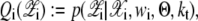 |
(23) |
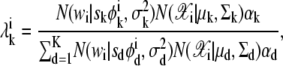 |
(24) |
where
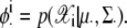 |
Step 2: M-step (Maximization)
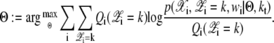 |
(25) |
For each k,
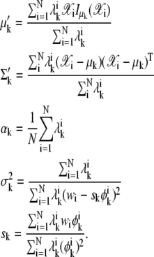 |
(26) |
 |
The indicator function  is 1 if
  Otherwise,
  is 0. In this article, ρ is assumed known as 10 and the initial value for the mixing coefficient αk is set to 1/K for k = 1, 2, ···, K.
Specification of model order
To obtain the best clusters among those generated by EM algorithm, we calculate the joint posterior distribution of μ and K by spatial point processes which specify both the likelihood and prior distribution of cluster centers given the observations. Thus, the likelihood and prior models allow interactions between the underlying landmarks, interactions between observations and restrictions to a portion of the observations as in McKeague and Loizeaux (33). Further, the observation and the cluster centers are assumed to be Poisson-distributed as in Castelloe and Zimmerman (34).
The observed point configuration which arises from the landmarks μ will be denoted  and is assumed to be a nonempty set. As well, the background noise is taken to have its own point process. That is, our model for clustering has three different point processes superimposed: point processes for μ,
  and background noise on W. The prior distribution of landmarks corresponds to a point process μ having density pμ(μ). The daughters 𝒳 are generated by landmarks when it falls in a silhouette region S(μ) ⊂ W given by
 |
(27) |
where D(ξ, rsil) = {c ∈ W: ‖c – ξ‖ ≤ rsil} and ‖ · ‖ is Euclidean distance. Here, ⊕ denotes the Minkowski addition and the grain G is the ball of radius r centered at the origin. Now, the probability of interest is  where K is the number of clusters and υ is the parameter rate for the number of clusters in Poisson distribution
 |
(28) |
In this article, we set to l = 0.6 and rsil = 3. First, we use a silhouette region S(μ),
 |
(29) |
The unnormalized likelihood function is designed with a Neyman-Scott model in which the observation process 𝒳 is the superposition of K independent inhomogeneous Poisson processes and a background Poisson noise process of intensity ε > 0. We assume that the prior pμ(μ) is locally stable as in McKeague and Loizeaux (33) and then we obtain
 |
(30) |
 |
(31) |
and
 |
(32) |
The unnormalized prior density f(μ) is assumed to follow a Strauss process. The Strauss process only models repulsive pairwise interaction
 |
(33) |
Here, β > 0, 0 < γ ≤ 1 and t(μ) is the number of unordered pairs of points in μ which are within a specified distance r of each other. Since we assumed that the observation and cluster centers follow Poisson distributions, clearly K|υ ∼ Poiss(υTxTy), and so we have
 |
(34) |
where υ is defined to  /(TxTy)2 and we set to β = 1.3, γ = 0.001, and r = 3 in this article. However, if the spot size is much bigger than the size of a spot in the current model for this article or a spot frequently moves much longer distance, the parameters should be changed.
Classifying real spots from K candidates for spots
Let  be the best estimated number of the clusters by the above clustering and model ordering strategies. This means the number of the candidates of real spots. Unfortunately, some candidates may be false spots since EM algorithm clusters the noisy data as well as real spots. Therefore, the number of real spots is rather different from
  To classify the real spots from artifacts, we can use the weight information within each cluster. Let w+(k) be
  Therefore, the kth candidate is regarded as a real spot if w+(k) ≥ α*. Otherwise, it is assumed to be an artifact. We can choose the α* in (0, 1] deterministically and we set α* to 0.1 in this article. This is different from conventional threshold determination in that α* is not dependent on SNR. We chose a low value of α* at 0.1 to ensure that the SMC method did not miss any real spots.
Implementation
In this article, we run the simulation with MatLab (The MathWorks, Natick, MA) on a Pentium CPU at 3.20 GHz. When an image sequence consists of 50 frames and each frame has 50 × 50 size and there are approximately five spots in each frame, it takes ∼150 min with 1000 samples to process and analyze the image sequences. The complexity of our SMC algorithm depends less on the size of a frame but more on the number of spots in a frame. We also coded a deterministic method (8) for comparison.
RESULTS
Synthetic data
To evaluate our tracking algorithm it is necessary to generate artificial data which resembles the data we want to analyze. This is important when we analyze robustness of the algorithm against blinking or low signal/noise as these might be related to the characteristics of movement of our objects. Simulated data with constant step size might not be sufficient in this case. Therefore we generated random walks using Algorithm 4 which have distributions of step sizes and diffusion coefficients expected for diffusion processes in two dimensions (6). The time in the generated data is represented in the frame number and the x and y coordinates in pixel numbers. The mean-squared distance for a single step is chosen to be 0.45 pixel. Under our experimental conditions, as described in Bruckbauer et al. (6) and below, this corresponds to a diffusion coefficient of 0.059 μm2/s. Each position of the random walk is then used to generate a Gaussian function of width and intensity. Gaussian noise is added to the intensity. An image is then created from all the Gaussian profiles and Gaussian background noise with standard deviation σN is added. The signal/noise ratio (SNR) is defined by
 |
(35) |
where Ik denotes the peak intensity of the kth spot.
Algorithm 4: Generating random walk for artificial data
set up dl to a small value (0.01, 0.015, or 0.02)
for t = 1 to T do
for k = 1 to K do
dl = 0.01, lx = 0, ly = 0;
for i = 1 to 1000 do
u ∼ {1, 2, 3, 4};
if u = 1, lx = lx + dl, ly = ly + dl
if u = 2, lx = lx + dl, ly = ly − dl
if u = 3, lx = lx − dl, ly = ly + dl
if u = 4, lx = lx − dl, ly = ly − dl
end for


end for
Make K Gaussian profiles, Vk.
Mix K radial images into make a image and add it to St. That is,
Generate St by adding Gaussian noise in the image,
end for
Trajectory of positions
Our sequential Monte Carlo is compared to a deterministic approach based on nonlinear least-square fitting of Gaussians (8). For real data the right threshold is usually not known. If a molecule cannot be detected in one frame but appears again in the next frame, this algorithm stops the first trajectory and starts a new trajectory. If this often happens in one image sequence due to incorrect thresholds or low signal/noise ratio, the algorithm produces a large number of small trajectories. The SMC method may link such short trajectories resulting in longer trajectories which are close to the ground truth. As synthetic data for the ground truth, we generated five trajectories of length 50 with SNR varying between 1.5 and 3.5. Fig. 1 a is the first frame of the synthetic image sequence and the two-dimensional plots of these trajectories are shown in Fig. 1 b. Trajectories obtained from the generated image sequences by the deterministic method (with different thresholds) and our SMC algorithm (with variable number of samples) are shown in Fig. 2. In the figure only trajectories with more than five steps are plotted and the numbers denote the length of each trajectory. As can be seen in Fig. 2 and Table 1, results from the deterministic approach vary with thresholds. The deterministic method detects all trajectories in full length and no additional (false) trajectories when the correct threshold is used (see Fig. 2 b). However, if a lower threshold is used, we obtain the five trajectories of interest (red) but also 33 artifacts (see Fig. 2 a). With a higher threshold, the deterministic method cuts the trajectories into several shorter pieces because they are separated by weak spots (see Fig. 2 c). In comparison, our proposed SMC method tracks well and detects weak spots which fail to be found in the threshold-based deterministic method. It therefore links shorter tracks together and detects trajectories which are close to the ground truth. We find that the length and the number of trajectories are almost stable in our SMC method even with a small number of samples.
FIGURE 1.

Synthetic data with five tracks: (a) the first frame of the synthetic image sequence and (b) the ground truth trajectories.
FIGURE 2.

Comparison of trajectories detected by a deterministic method with variable thresholds and by SMC method with different sample size: (a) by a deterministic method with a low threshold 22; (b) by a deterministic approach with a proper threshold 50; (c) by a deterministic approach with a high threshold 90; (d) by SMC method with 100 samples used in the Monte Carlo scheme; (e) by SMC method with 1000 samples used; and (f) by SMC method with 2000 samples used.
TABLE 1.
Comparison of the lengths of trajectories and RMSE for positions
| Methods | Full tracks detected | Only matched tracks | RMSE ( ) for position ) for position |
|---|---|---|---|
| Deterministic method (low threshold, 22) | 451 | 250 | 0.3903 |
| Deterministic method (proper threshold, 50) | 250 | 250 | 0.3903 |
| Deterministic method (high threshold, 90) | 159 | 159 | 0.3715 |
| Sequential Monte Carlo (100 samples) | 249 | 249 | 0.3370 |
| Sequential Monte Carlo (1000 samples) | 248 | 248 | 0.2836 |
| Sequential Monte Carlo (2000 samples) | 249 | 249 | 0.2804 |
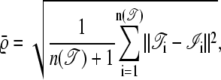
It is also important to know how accurately the two algorithms determine the positions of the molecules. Here we can directly compare the ground truth with the detected trajectories and calculate the root mean-square error (RMSE)  to compare the position accuracy. When n(·) is the length of the interesting trajectories, then the RMSE is defined by
 |
(36) |
where T and I denote positions for the estimated tracks and the ideal tracks, respectively. Compared to the deterministic approach using the right threshold (RMSE = 0.39 pixel), our SMC approach has a higher accuracy (RMSE = 0.28 pixel). We can compare these values to the theoretical position accuracy for the fitting two-dimensional Gaussians in the case of background dominated noise according to the literature (35,36). The mean-square error for the position of a two-dimensional Gaussian of width σ, intensity C (in photon counts), when a background noise of standard deviation σN is present and the signal is recorded with a detector of pixel size a, is given by (35)
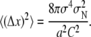 |
(37) |
For a two-dimensional Gaussian the number of photon counts is related to the signal amplitude I and pixel width through
 |
(38) |
so that the equation for the position error can be simplified to
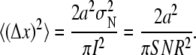 |
(39) |
For a SNR of 3, we get a RMSE of 0.27 pixel, which is very close to the value of 0.28 pixel obtained for our SMC approach.
Disappearing spots
Our automatic SMC approach is designed to deal with appearing and disappearing objects, the latter is an important feature of all single molecule fluorescence measurements because of photobleaching of the fluorophores. We have to evaluate how accurately our proposed method detects disappearing spots. This means that we have a variable number of spots in each frame. Dealing with a variable number of spots is an important issue in that our SMC algorithm is based on a trans-dimensional approach. Fig. 3 a shows a two-dimensional plot for the ground truth which has several varying lengths of tracks. Meanwhile, Fig. 3, b and c, plot the trajectories by the deterministic approach with a proper threshold 50 and by the SMC algorithm.
FIGURE 3.

Comparison of variable length tracks: (a) ground truth, (b) deterministic method, and (c) SMC method.
The number of spots detected by the deterministic method and our proposed method are compared in Fig. 4. In this figure, the deterministic approach with the proper threshold detects all objects when they appear in the image sequence and detects only one false position when an object is removed. However, if we use a lower threshold than the proper threshold, a large number of false objects are detected due to noise being detected as signal as shown with thresholds 20 and 25 in Fig. 4 a. Meanwhile, if we use a higher threshold (120) than the proper threshold, we lose many weak spots. However, even though our SMC approach does not require the threshold, it detects a number of spots very close to the ground truth, as shown in Fig. 4 b.
FIGURE 4.

The number of spots detected (dimension, K): (a) comparison of the number of spots by deterministic method with four different threshold with 20, 25, 50, 120, and (b) comparison of the number of spots by deterministic method with a threshold 50 and our SMC algorithm.
Robust against a single blink
The next issue to be considered is that of reconstructing the lost positions by a single blink, defined by a complete loss of signal in a single frame. Fig. 5 a shows ground truth of the signals with a single blink every five steps. Fig. 5, b and c, plot the trajectories by the deterministic and SMC approaches, respectively. As we can see, our proposed approach can restore most of the underlying tracks (Fig. 5 c) from blinking signals using spatial and temporal information. Our proposed SMC tracking method finds many underlying tracks which the deterministic approach cannot restore. Moreover, our proposed method restores >75% of the underlying positions, which, by using spatial and temporal information, are removed by blinking.
FIGURE 5.

Images with single blinking signals: (a) trajectories for ground truth; (b) trajectories longer than five steps by a deterministic method; and (c) detected tracks longer than five steps by SMC method.
Robust against low signal/noise ratio
The last issue to consider in this article is that of the robustness against low signal/noise ratio. While single fluorophores undergo a sudden loss of intensity from one frame to the other (single-step photobleaching), the fluorescence can also change due to change in the fluorophore orientation, change in the local environment, or change in the illumination intensity due to absorption of laser light by other features underneath the cell membrane. Furthermore, molecules which are labeled with more than one fluorophore can undergo stepwise photobleaching. We model these changes using several objects of decreasing intensity. We generate five tracks with different initial intensities in the 100 frames. The intensities of all tracks decrease as time goes on, as shown in Fig. 6. The corresponding images in time series are shown in Fig. 7. While we can see all spots in the first frame of Fig. 7, it is hard to find spots at the last frame. In Fig. 8, we compare the results of the deterministic method and the SMC method with the ground truth. This figure demonstrates that the SMC method detects many weak spots which may not be found in the deterministic approach. Because of the fixed threshold used in the deterministic approach, it loses the track when the signal is lower than the threshold. However, our proposed approach detects longer trajectories since it does not require an optimum setting for the threshold.
FIGURE 6.

Five spots with decreasing SNR with frame number.
FIGURE 7.

Images with decreasing intensities at six different time: 1, 5, 70, 80, 90, and 100 (synthetic data).
FIGURE 8.

Comparison of trajectories with decreasing intensities (synthetic data): (a) ground truth, (b) trajectories by a deterministic method, and (c) trajectories by SMC.
Experimental data
To test the SMC approach against the deterministic method on experimental data we reanalyzed two image sequences from a previously published study of Atto 647-labeled wheat germ agglutinin diffusing on the cell membrane of live boar spermatozoa (6). These videos are available in Supplementary Materials, Data S1, and Movie S1, Movie S2, Movie S3, Movie S4, Movie S5, and Movie S6. Fluorescence was excited with a HeNe laser (LHP 925, Melles Griot, CA) at 632.8 nm in total internal reflection geometry and image sequences were recorded using a highly sensitive back-thinned electron multiplying CCD camera (Cascade II 512B, Photometrics, Tucson, AZ). Time intervals were 0.025 s and pixel size 0.170 μm.
In Fig. 9, there are four plots: trajectories longer than five steps detected by the deterministic method (Fig. 9 a), trajectories longer than five steps detected by the SMC method (Fig. 9 b), trajectories longer than 20 steps detected by the deterministic method (Fig. 9 c), and trajectories longer than 20 steps detected by our SMC method (Fig. 9 d). As can be seen in this figure, our SMC algorithm has two benefits: fewer artifacts and longer tracks.
FIGURE 9.

Comparison with experimental data: (a) trajectories longer than five steps detected by the deterministic method; (b) trajectories longer than five steps detected by the SMC method; (c) trajectories longer than 20 steps detected by the deterministic method; and (d) trajectories longer than 20 detected by SMC method.
In addition, Fig. 10, b and c, show two-dimensional figures longer than 10 steps for the second set of experimental data. These figures show that the track at [15, 35] is detected only by the SMC method. The SNR of the weak spot varies between 0.5 and 0.75. The deterministic method cannot find this track since the threshold is higher than the signal. We also investigated the region circled in a dotted line in both figures. In Fig. 10, panels d–f are the comparisons of the trajectories for the same periods of time in this circled region using SMC. By using the SMC method, we can see longer tracks in Fig. 10, d–f, as shown in Table 2. For example, it can be seen in Fig. 10 d that a long track can be split by the deterministic method into several tracks because of blinking.
FIGURE 10.

Comparison with a second set of experimental data: (a) 78th frame from the experimental data. (b and c) Full trajectories found by a deterministic method and by SMC, respectively; and panels d–f compare the tracks by a deterministic method and SMC for the same period of time in the dotted and circled region in panels b and c.
TABLE 2.
Comparison of the lengths of trajectories of Fig. 10
| Lengths | Deterministic | SMC method |
|---|---|---|
| (d) (SNRs: 0.70 ∼ 2.00) | 11 + 11 | 34 |
| (e) (SNRs: 0.34 ∼ 1.20) | 10 | 24 |
| (f) (SNRs: 0.34 ∼ 1.13) | 13 | 43 |
Fig. 11, a and b, show that our SMC method gives more accurate and better trajectories when two tracks become close. When tracks A and B become close, the deterministic method cannot find one of the tracks due to the difficulty in separating these close tracks. However, SMC method detects two tracks until they meet. When two tracks meet, a trajectory stops and the other trajectory continues. This still provides additional information compared to the deterministic method which has shorter and missing tracks. Moreover, Fig. 11, c and d, shows that the deterministic approach may also incorrectly link two tracks B and C, which should be separated. In contrast the SMC method found two separated tracks.
FIGURE 11.

(a and b) Trajectories found by a deterministic method and SMC respectively for two close spots. (c and d) The deterministic approach can incorrectly link two different tracks.
DISCUSSION
Future works
A future concern with our method is how to reduce the time complexity which increases as the number of spots increases. In cases with more spots than shown in this article in a frame, we may need impractically large number of samples to obtain full posterior distribution for tracking since we are considering the joint full posterior distribution. Therefore, we may need to develop a more efficient and practical algorithm, which requires small numbers of samples.
Another concern is to design good parameter association schemes to identify spots among samples for our trans-dimensional sequential Monte Carlo method based on track-before-detect. In this article, we have used a clustering algorithm (EM clustering) for the parameter association, although it is rather slow and occasionally gives incorrect results when the initial positions are chosen badly. Thus, we will develop better algorithms for parameter association to identify and estimate parameters. Also, we determine the model order by applying spatial point processes, which specify both likelihood and prior distribution of the cluster centers obtained by the EM algorithm. However, we may associate the parameters and obtain model order by directly using spatial point processes rather than via EM clustering. This unifying scheme may reduce the time complexity and improve the performance of our SMC tracking algorithm.
CONCLUSION
We have proposed a trans-dimensional sequential Monte Carlo method for tracking single molecules and compared it with a well-known deterministic method. Although the SMC method based on the Bayesian sequential estimation framework is rather slow, it has many benefits compared to the deterministic method when we have prior information such as the mean of diffusion coefficients, the dimensions, and fluorescence intensity of the spots of interest. Our proposed method can detect weak signals and make closer estimates to real trajectories than the deterministic method. Also, the SMC method can restore lost positions caused by single blinks since it considers spatiotemporal information in the sequence of images. Lastly, our proposed algorithm can deal with the disappearance of objects due to photobleaching of the fluorophores. These improvements should enable greater and more accurate data about the trajectories of diffusing molecules to be obtained, even when the signal/noise is low, and hence help to improve our understanding of the structure of the cell membrane.
SUPPLEMENTARY MATERIAL
To view all of the supplemental files associated with this article, visit www.biophysj.org.
Supplementary Material
Acknowledgments
Authors and this project are supported by Biotechnology and Biological Sciences Research Council funds.
Editor: Michael Edidin.
References
- 1.Ambrose, W. P., P. M. Goodwin, J. H. Jett, A. V. Orden, J. H. Werner, and R. A. Keller. 1999. Single molecule fluorescence spectroscopy at ambient temperature. Chem. Rev. 99:2929–2956. [DOI] [PubMed] [Google Scholar]
- 2.Moerner, W. E., and D. P. Fromm. 2003. Methods of single-molecule fluorescence spectroscopy and microscopy. Rev. Sci. Instrum. 74:3597–3619. [Google Scholar]
- 3.Nie, S., and R. N. Zare. 1997. Optical detection of single molecules. Annu. Rev. Biophys. Biomol. Struct. 26:567–596. [DOI] [PubMed] [Google Scholar]
- 4.Bonneau, S., L. Cohen, and M. Dahan. 2004. A multiple target approach for single quantum dot tracking. In IEEE International Symposium on Biomedical Imaging: From Nano to Macro. Arlington, VA.
- 5.Sage, D., F. R. Neumann, F. Hediger, S. M. Gasser, and M. Unser. 2005. Automatic tracking of individual fluorescence particles: application to the study of chromosome dynamics. IEEE Trans. Image Process. 14:1372–1383. [DOI] [PubMed] [Google Scholar]
- 6.Bruckbauer, A., P. James, D. Zhou, J. Yoon, D. Excell, Y. Korchev, R. Jones, and D. Klenerman. 2007. Nanopipette delivery of individual molecules to cellular compartments for single molecule fluorescence tracking. Biophys. J. 93:3120–3131. [DOI] [PMC free article] [PubMed] [Google Scholar]
- 7.Goulian, M., and S. M. Simon. 2000. Tracking single proteins within cells. Biophys. J. 79:2188–2198. [DOI] [PMC free article] [PubMed] [Google Scholar]
- 8.Crocker, J., and D. G. Grier. 1996. Methods of digital video microscopy for colloidal studies. J. Colloid Interface Sci. 179:298–310. [Google Scholar]
- 9.Enderlein, J. 2000. Positional and temporal accuracy of single molecule tracking. Single Mol. 1:225–230. [Google Scholar]
- 10.Thomann, D., J. Dorn, P. K. Sorger, and G. Danuser. 2003. Automatic fluorescent tag localization II: improvement in super-resolution by relative tracking. J. Microsc. 211:230–248. [DOI] [PubMed] [Google Scholar]
- 11.Anthony, S., L. Zhang, and S. Granick. 2006. Methods to track single-molecule trajectories. Langmuir. 22:5266–5272. [DOI] [PubMed] [Google Scholar]
- 12.Ristic, B., S. Arulampalam, and N. Gordon. 2004. Beyond the Kalman Filter: Particle Filters for Tracking Applications. Artech House, Norwood, MA.
- 13.Yoon, J., and S. J. Godsill. 2006. Bayesian inference for multidimensional NMR image reconstruction. European Signal Processing Conference (EUSIPCO). Florence, Italy.
- 14.Yoon, J., S. J. Godsill, C. Kang, and T. Kim. 2007. Bayesian Inference for 2D gel electrophoresis image analysis. In Bioinformatics Research and Development (BIRD), Lecture Note in Bioinformatics. Springer, New York.
- 15.Kreucher, C., K. Kastella, and A. O. Hero III. 2005. Multitarget tracking using a particle filter representation of the joint multitarget density. IEEE Trans. Aerosp. Electron. Syst. 39:1396–1414. [Google Scholar]
- 16.Salmond, D. J., and H. Birch. 2001. A particle filter for track-before-detect. Proc. Am. Control Conf. 5:3755–3760. [Google Scholar]
- 17.Sbalzarini, I. F., and P. Koumoutsakos. 2005. Feature point tracking and trajectory analysis for video imaging in cell biology. J. Struct. Biol. 151:182–195. [DOI] [PubMed] [Google Scholar]
- 18.MacKay, D. J. 2003. Information Theory, Inference, and Learning Algorithms. Cambridge University Press, Cambridge, UK.
- 19.Bernardo, J., and A. F. M. Smith. 1995. Bayesian Theory. Wiley, New York.
- 20.Neumann, J. 1951. Various techniques used in connection with random digits. In National Bureau of Standards Applied Mathematics Series, Vol. 12. National Bureau of Standards, Washington, DC.
- 21.Marshall, A. 1956. The use of multi-stage sampling schemes in Monte Carlo computations. Symposium on Monte Carlo Methods, New York.
- 22.Liu, J. S. 2001. Monte Carlo Strategies in Scientific Computing. Springer, New York.
- 23.Rubin, D. B. 1987. A noniterative sampling/importance resampling alternative to the data augmentation algorithm for creating a few imputations when fractions of missing information are modest: the SIR algorithm. J. Am. Stat. Assoc. 52:543–546. [Google Scholar]
- 24.Doucet, A., N. de Freitas, and N. Gordon. 2001. Sequential Monte Carlo Methods in Practice. Springer, New York.
- 25.Doucet, A., S. Godsill, and C. Andrieu. 2000. On sequential Monte Carlo sampling methods for Bayesian filtering. Stat. Comput. 10:197–208. [Google Scholar]
- 26.Lie, J. S., and R. Chen. 1998. Sequential Monte Carlo methods for dynamic systems. J. Am. Stat. Assoc. 93:1032–1044. [Google Scholar]
- 27.Moral, P. D., A. Doucet, and A. Jasra. 2006. Sequential Monte Carlo samplers. J. Roy. Stat. Soc. B. 68:411–436. [Google Scholar]
- 28.Vermaak, J., S. J. Godsill, and A. Doucet. 2003. Radial basis function regression using trans-dimensional sequential Monte Carlo. IEEE Workshop on Statistical Signal Processing. DOI:10.1109/SSP.2003.1289519.
- 29.Casella, G., and C. P. Robert. 1996. Rao-Blackwellization of sampling schemes. Biometrika. 83:81–94. [Google Scholar]
- 30.Reed, I. S., and X. Yu. 1990. Adaptive multiple-band CFAR detection of an optical pattern with unknown spectral distribution. IEEE Trans. Acoust. Speech Signal Process. 38:1760–1770. [Google Scholar]
- 31.Arulampalam, M. S., S. Maskell, N. Gordon, and T. Clapp. 2002. A tutorial on particle filters for online nonlinear/non-Gaussian Bayesian tracking. IEEE Trans. Signal Process. 50:174–188. [Google Scholar]
- 32.Bilmes, J. 1997. A gentle tutorial on the EM Algorithm and its application to parameter estimation for Gaussian mixture and hidden Markov models. Technical report No. ICSI-TR-97–021, University of Berkeley, Berkeley, CA.
- 33.McKeague, I. W., and M. A. Loizeaux. 2002. Perfect sampling for point process cluster modeling. In Spatial Cluster Modeling. Chapman and Hall, Boca Raton, FL.
- 34.Castelloe, J. M., and D. L. Zimmerman. 2002. On maximum likelihood estimation of a spatial Poisson cluster process. Technical Report 312, Department of Statistics and Actuarial Science, The University of Iowa, Iowa City.
- 35.Thompson, R. E., D. R. Larson, and W. W. Webb. 2002. Precise nanometer localization analysis for individual fluorescent probes. Biophys. J. 82:2775–2783. [DOI] [PMC free article] [PubMed] [Google Scholar]
- 36.Bobroff, N. 1986. Position measurement with a resolution and noise-limited instrument. Rev. Sci. Instrum. 57:1152–1157. [Google Scholar]
Associated Data
This section collects any data citations, data availability statements, or supplementary materials included in this article.