

Abstract
In an effort to develop better orthopedic implants, osteoblast (bone-forming cells) adhesion was determined on microscale patterns (30 μm lines) of carbon nanofibers placed on polymer substrates. Patterns of carbon nanofibers (CNFs) on a model polymer (polycarbonate urethane [PCU]) were developed using an imprinting method that placed CNFs in selected regions. Results showed the selective adhesion and alignment of osteoblasts on CNF patterns placed on PCU. Results also showed greater attraction forces between fibronectin and CNF (compared with PCU) patterns using atomic force microscope force-displacement curves. Because fibronectin is a protein that mediates osteoblast adhesion, these results provide a mechanism of why osteoblast adhesion was directed towards CNF patterns. Lastly, this study showed that the directed osteoblast adhesion on CNF patterns translated to enhanced calcium phosphate mineral deposition along linear patterns of CNFs on PCU. Since CNFs are conductive materials, this study formulated substrates that through electrical stimulation could be used in future investigations to further promote osteoblasts to deposit anisotropic patterns of calcium-containing mineral similar to that observed in long bones.
Keywords: carbon nanotubes, carbon nanofibers, osteoblasts, orthopedic, biomaterials, alignment
Introduction
Materials now used as orthopedic implants, such as titanium and its alloys, have an average functional lifetime of only 10–15 years (AAOS 2005). One major reason for orthopedic implant failure is the lack of sufficient integration of the implanted material into juxtaposed bone. Poor integration of an orthopedic implant into surrounding bone can cause detrimental wear debris as well as stress and strain imbalances at the tissue–implant interface, leading to loosening and eventual failure (Kaplan et al 1994). Because of these problems, there has been an increasing interest in developing better biomaterials to promote bone growth for the orthopedic field.
One specific material classification, carbon nanofibers, has demonstrated some success towards improving orthopedic applications (Hartgerink et al 2001; Martin and Kohli 2002). This is because carbon nanofibers are lightweight, strong, and can be formulated to mimic the initial nanometer structures of components of bone, such as hydroxyapatite and collagen (Webster 2001). Although mature hydroxyapatite exists as rectangular crystals, when initially formed hydroxyapatite crystals bond to collagen to form composite nanofibers. Moreover, bone cell functions are stimulated under electrical current (Supronowicz et al 2002), and therefore conductive nanophase materials (like carbon nanofibers) may also play a role in promoting osteoblast (bone-forming cells) activity necessary for increasing the lifetime of current orthopedic devices. For example, if osteoblast adhesion can be directed towards conductive regions of a substrate, electrical stimulation could be used to further promote bone growth.
Importantly, previous studies have shown greater osteoblast viability (Price et al 2004), adhesion (Price et al 2003; Webster et al 2003), proliferation, synthesis of extracellular matrix proteins (such as alkaline phosphatase) (Elias et al 2002), and deposition of calcium-containing mineral (Elias et al 2002) on carbon nanofiber-based materials compared with currently used titanium. In addition, enhanced functions of osteoblasts have been reported on polycarbonate–urethane composites containing from 0%–25% by weight of carbon nanofibers (Price et al 2003). Equally as promising, decreased functions of fibroblasts (that is, cells that contribute to detrimental fibrous tissue encapsulation of orthopedic implants) have been documented on carbon nanofiber materials compared with the orthopedic implant materials now used (Price et al 2003). These studies highlight the optimal select interactions osteoblasts have with materials containing carbon nanofibers important for improving orthopedic applications.
A further advantage of carbon nanofibers for orthopedic devices could lie in their ability to mimic the alignment of collagen and hydroxyapatite in long bones. Hydroxyapatite and collagen are aligned in microscale patterns in long bones to provide for unique anisotropic mechanical, electrical, and chemical properties. The aforementioned studies on carbon nanofiber–polymer composites were conducted on randomly oriented carbon nanofibers. To mimic this alignment in natural bone, many research groups have created patterns of proteins such as fibronectin and vitronectin (which mediate osteoblast attachment) on various substrates using microcontact printing (Healy et al 1996; McFarland et al 2000). Their results clearly show corresponding alignment of osteoblasts and subsequent deposition of calcium-containing mineral on such micropatterns similar to that observed naturally in bone (Healy et al 1996; McFarland et al 2000).
However, these protein patterns cannot serve as regions to further promote osteoblast functions through electrical stimulation, whereas aligned patterns of carbon nanofibers could be used to stimulate osteoblasts to deposit anisotropic bone. Since bone is an electrically active organ, the objective of this in vitro study was to determine osteoblast functions on micropatterns of carbon nanofibers placed on polymer substrates. If successful at directing osteoblast adhesion to carbon nanofiber regions, through an applied voltage, such carbon nanofiber patterns could promote bone formation needed for enhancing orthopedic implant efficacy.
Materials and methods
Materials
Microscale patterns of carbon nanofibers on polycarbonate urethane
Carbon nanofibers (CNFs) produced by carbon vapor deposition were obtained from Applied Sciences Inc (Cedarville, OH, USA). These CNFs have a polynuclear aromatic hydrocarbon (PAH) layer, called a pyrolytic layer, formed during the production process. Besides hydrophobic properties, CNFs with pyrolytic insulating outer layers have lower surface energies, approximately 25 mJ/m2, than pyrolytic-free CNFs, approximately 80 mJ/m2 (material specification, Applied Sciences Inc). Only the pyrolytic insulating outer layer (ie, low surface energy) CNFs were used in the present study. The CNFs with a pyrolytic layer were 100 nm (± 2.5 nm) in diameter and up to 20 μm (± 4.5 μm) long (Price et al 2003). According to previous studies, no impurities were detected in the low-surface-energy CNFs using electron spectroscopy for chemical analysis (ESCA) (Price et al 2003).
To create microscale patterns of CNFs on a polymer, an FDA-approved polycarbonate urethane (PCU, catalog nr PC-3575A, Thermedics, Wilmington, DE, USA) was used. PCU is an FDA-approved polymer for implantation, is frequently studied for orthopedic applications (due to its high strength and durability), and is nondegradable. PCU (5 g) was dissolved in chloroform (8 ml; Sigma-Aldrich, St Louis, MO, USA) while the CNFs mentioned above in ethanol (70% concentration by volume) were added. The PCU–CNF mixture (75:25% by weight) was then sonicated for 30 minutes at room temperature to aid in the dispersion of CNFs in PCU. Meanwhile, PCU in chloroform (prepared as described above) was dip coated on a borosilicate glass slide (catalog nr 12-550-15, Fisher-Scientific, Chicago, IL, USA) and placed in a vacuum oven for 48 hours at room temperature to evaporate all the chloroform (Figure 1b). A Au-coated grid with grooves (widths of 20 μm, catalog nr 2422G-XA, SPI Supplies, West Chester, PA, USA) was then placed on top of the PCU coating (Figure 1c). The CNF-containing PCU solution was then placed into the grooves of the Au grid by a micropipette (Figure 1d). The grid with imbedded CNFs on top of the PCU-coated glass was then placed in a vacuum oven for 48 hours, after which the Au grid was removed, the substrate rinsed with deioinized water, and microscale patterns of CNFs on PCU were created (Figure 1e).
Figure 1.
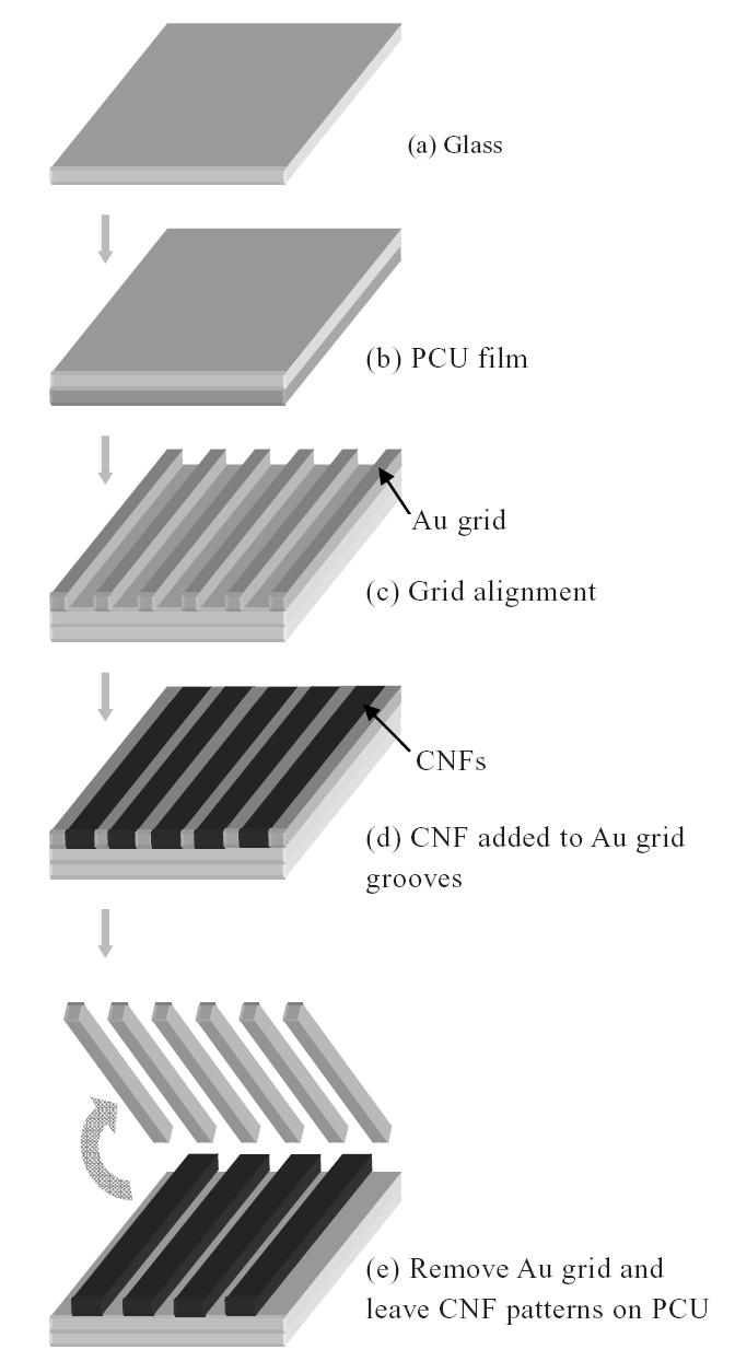
Schematic diagram of creating carbon nanofiber (CNF) patterns on a polycarbonate urethane (PCU) matrix.
Control materials
Control materials consisted of pure PCU, pure CNF, and composites of PCU without patterned CNFs. To prepare pure PCU, similar to above, PCU pellets were dissolved in chloroform, placed in a vacuum oven for 48 hours, and cut into squares (1 cm2). To prepare pure CNFs, individual CNFs were pressed into compacts using well-established room temperature serial compression (Elias et al 2002). Specifically, CNFs (0.005 g) were loaded into a steel-tool die and were pressed with 2 GPa of pressure for 2 minutes, then with 4 GPa for 2 minutes. The compact (1 cm2 diameter) was then removed from the die. Lastly, to prepare PCU without aligned patterns of CNFs, CNFs at 25% by weight were added to PCU solubilized in chloroform in a petri dish. The mixture was then sonicated (to disperse the CNFs), placed in a vacuum oven for 48 hours, and cut into desired shapes (1 cm2) according to established procedures (Price et al 2003).
All substrates were sterilized by exposure to UV light for 24 hours before cell culture. Previous studies demonstrated no chemical changes in any of the aforementioned substrates due to UV light exposure (Price et al 2003).
Osteoblast experiments
Adhesion
Osteoblasts (CRL-11372, American Type Culture Collection, population nrs 2–5) were cultured on the different substrates under standard cell culture conditions (ie, a 37°C, humidified, 5% CO2/95% air environment). Osteoblasts were cultured in Dulbecco’s modified eagle medium (DMEM; Invitrogen, Carlsbad, CA, USA) supplemented with 10% fetal bovine serum (FBS; Hyclone, Logan, UT, USA) and 1% penicillin–streptomycin (P–S; Hyclone) under standard cell culture conditions. Human osteoblasts were seeded at a density of 2000 cells/cm2 (subconfluent) onto each substrate and were incubated under standard cell culture conditions in osteoblast growth media (DMEM, 10% FBS, and 1% P–S) for 2 days. Nonadherent cells were then removed by rinsing in PBS while adherent cells were fixed with 4% formaldehyde (Fisher) and stained with Rhodamine Phalloidin (R415; Invitrogen) to visualize f-actin filaments. Hoechst dye (33258, Sigma-Aldrich) was also used to visualize the cell nucleus.
Deposition of calcium phosphate crystals
To determine subsequent osteoblast functions (such as the deposition of calcium phosphate crystals), osteoblasts were cultured on the substrates of interest for 21 days in DMEM supplemented with 10% FBS, 1% P–S, 10 mM β-glycerophosphate (Sigma-Aldrich), and 50 μg/ml ascorbic acid (Sigma-Aldrich) under standard cell culture conditions. Media were replaced every other day. Osteoblasts were seeded at a density of 50 000 cells/cm2 onto each substrate. At the end of the prescribed time period, osteoblasts were lysed using 3 freeze-thaw cycles in deionized water. The remaining mineral deposits on the substrates were visualized by scanning electron microscopy (SEM; JSM-840, JEOL, Peabody, MA, USA) as described below and their chemical composition was determined by energy-dispersive spectroscopy (EDS) according to standard techniques.
Surface characterization
Topography of the CNF patterns on PCU was evaluated by SEM (JSM-840, JEOL). For this purpose, CNF patterns–PCU composites were mounted using double-stick carbon tape and sputter coated with AuPd prior to imaging at room temperature. They were visualized at low (100×) and high (500×) magnification at 5 kV. Cell images were taken using fluorescence microscopy (DM IRB, Leica, Bannockburn, IL, USA).
Fibronectin interactions with CNF patterns on PCU
Fibronectin is a key protein that mediates osteoblast adhesion (Kaplan et al 1994). To determine interactions between fibronectin and CNF patterns on PCU that may help explain osteoblast behavior, well-established atomic force microscope (AFM) force-displacement techniques were used (Reif et al 1997). AFM force-displacement curves were created between an AFM tip coated with fibronectin and CNF patterns on PCU. For this purpose, AFM tips (SiO2; 10 nm, Series 38, MikroMasch, Wilsonville, OR, USA) were submerged in fibronectin solutions (1 μg/ml for 1 hour at room temperature; Sigma-Aldrich) and then immediately brought into close contact with the substrates of interest. Resulting force-displacement curves were then used to determine the attraction force (nN) between the AFM tip coated with fibronectin and CNF compared with PCU patterns. A Nanoscope IIIa AFM (Veeco; Digital Instruments Inc, Santa Barbara, CA, USA) with Nanoscope software (version 4.31, Digital Instruments Inc) was utilized.
Statistical analyses
Experiments were conducted 3 separate times with 3 replicates per time. For experiments involving quantitative data, standard analysis of variance (ANOVA) tests with follow-up Student’s t-tests were conducted.
Results and discussion
CNF patterns on PCU
As expected, SEM results demonstrated patterns of CNFs (20 μm wide) imprinted onto PCU (Figure 2). Lines of CNF patterns were arranged 20 μm apart to control osteoblast alignment. Please note, however, that individual CNFs were not aligned by the techniques used here, but instead microscale patterns of CNFs on PCU were created.
Figure 2.
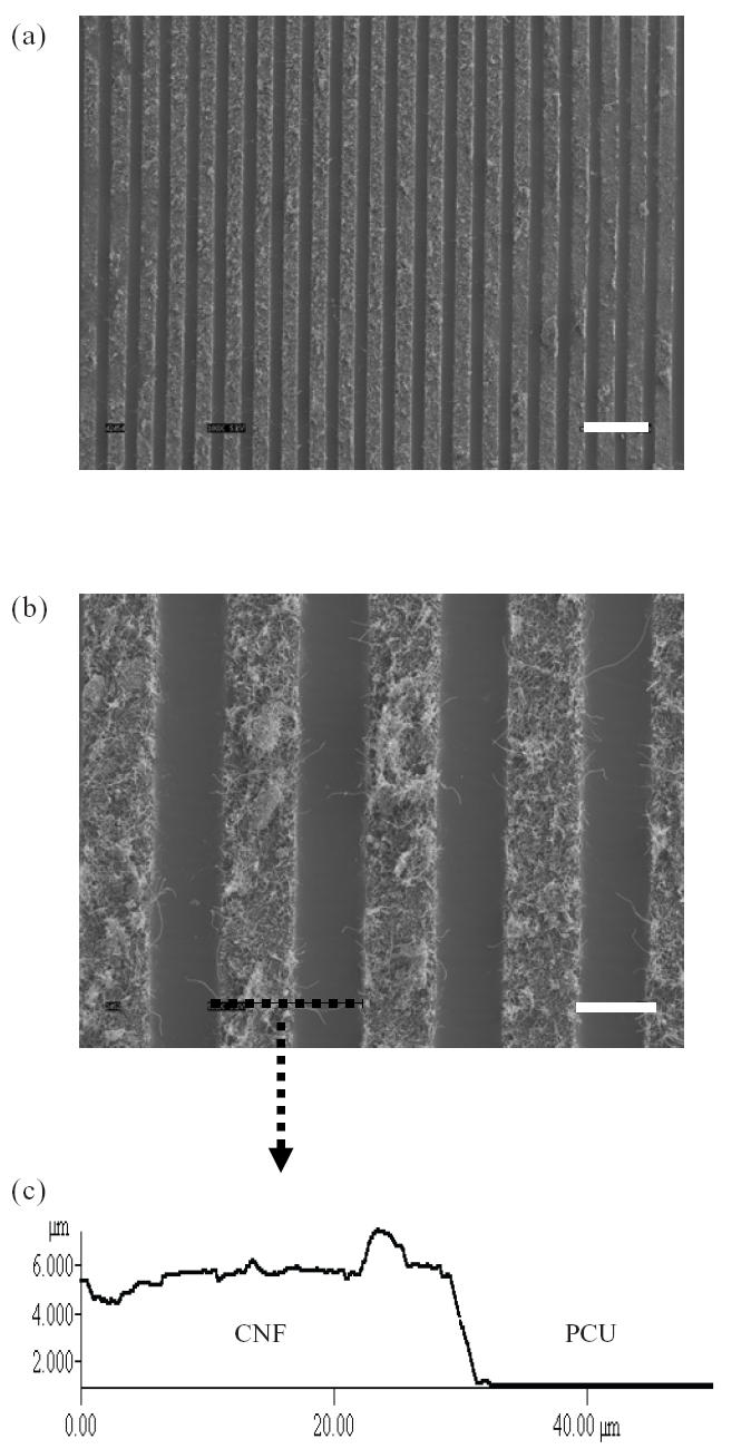
(a) Scanning electron microscope (SEM) image (100×, bar = 100 μm) of carbon nanofiber (CNF) patterns on polycarbonate urethane (PCU). (b) SEM image (500×, bar = 30 μm) of CNF patterns on PCU. (c) Atomic force microscope (AFM) vertical line profile of CNF and PCU.
Greater osteoblast adhesion on patterned PCU–CNF
More importantly, results showed that osteoblast adhesion was greater on CNFs than on PCU (Figure 3) for both pure CNFs compared with pure PCU and regions of CNF on PCU on the same substrate. Specifically, osteoblast adhesion was statistically greater (p < 0.01) on pure CNFs than on pure PCU and on regions of CNFs on PCU for the patterned composite. Osteoblast adhesion was statistically (p < 0.01) greater on patterned than on nonpatterned PCU–CNF composites; previous studies correlated greater osteoblast adhesion on non-patterned PCU–CNF composites with higher amounts of CNFs (Price et al 2003). Previous studies also demonstrated increased osteoblast adhesion on pure CNF substrates than on currently used orthopedic implant materials such as titanium and CoCrMo (Price et al 2003). Lastly, osteoblast adhesion was statistically similar between patterned PCU–CNF composites and pure CNF substrates.
Figure 3.
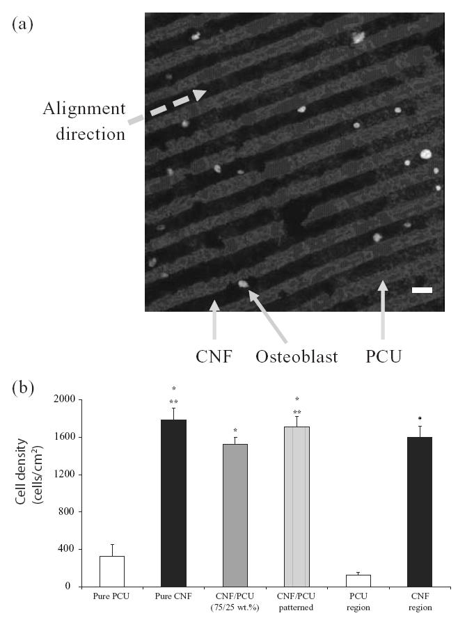
(a) Optical image of selective osteoblast adhesion on carbon nanofiber (CNF) patterns on polycarbonate urethane (PCU) after 2 days of culture (bar = 20 μm). (b) Increased osteoblast adhesion on patterned CNF–PCU compared with nonpatterned CNF–PCU. Values are mean +/– standard error of mean; n = 7; *p < 0.01 (compared with pure PCU or PCU regions) and **p < 0.01 (compared with PCU–CNF not patterned).
Alignment of osteoblasts on CNF patterns on PCU
As expected from the above results, this study also provided evidence of osteoblasts selectively adhering on CNF patterns on PCU after 2 days of culture (Figure 4). Specifically, since a greater number of osteoblasts adhered on CNF patterns compared with PCU regions, directed osteoblast adhesion on CNF regions was observed (Figure 4). When osteoblasts adhered on the center of CNF patterns, f-actin filaments were elongated with the aligned pattern of the CNF arrays (Figure 5). Similarly, if osteoblasts adhered on the edge of the CNF arrays, f-actin filaments were elongated with the direction of the adjacent CNF arrays (Figure 6). In contrast, no cytoskeleton alignment was observed when osteoblasts adhered specifically on the PCU patterns, which happened infrequently. Collectively, this provided evidence that osteoblasts preferred to adhere and align only on or at the interface of CNF patterns on PCU. Such results lay the foundation for future studies to electrically stimulate osteoblasts residing on the CNF regions to anisotropically deposit calcium-containing mineral; such patterns of bone deposition would match those observed in long bones in the body to potentially improve orthopedic implant applications.
Figure 4.
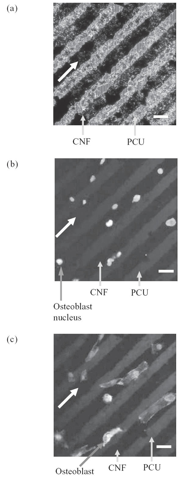
Fluorescence microscopy images of (a) carbon nanofiber (CNF) patterns on polycarbonate urethane (PCU), (b) selective osteoblast adhesion on CNF patterns on PCU, and (c) aligned osteoblast adhesion on CNF patterns on PCU. All bars = 20 μm; culture time = 2 days; all arrows show direction of CNF patterns.
Figure 5.
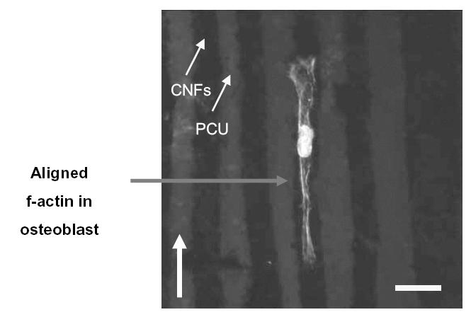
Fluorescence microscopy image of an osteoblast with aligned f-actin filaments parallel with carbon nanofiber (CNF) patterns on polycarbonate urethane (PCU). Bar = 20 μm; culture time = 2 days; arrow shows direction of CNF patterns.
Figure 6.
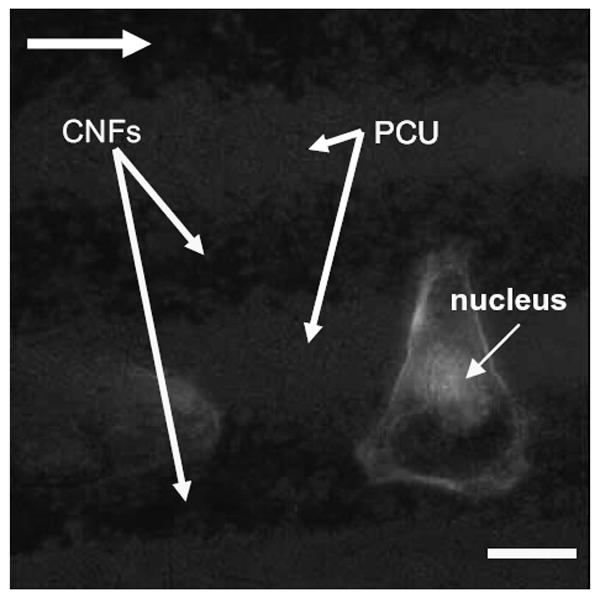
Fluorescence microscopy image of an osteoblast adherent at the edge of a carbon nanofiber (CNF) pattern in polycarbonate urethane (PCU). Note that for one osteoblast, f-actin filaments stretch across the PCU pattern to an adjacent CNF pattern. Bar = 10 μm; culture time = 2 days; arrow shows direction of CNF patterns.
Increased fibronectin interactions with CNF patterns on PCU
In an attempt to elucidate why osteoblast adhesion was directed towards CNF patterns on PCU, the present study determined attraction forces between fibronectin and CNF patterns using an AFM tip coated with fibronectin (Figure 7). Fibronectin is a serum protein that mediates osteoblast adhesion (Kaplan 1994). Moreover, previous studies have reported increased fibronectin adsorption on pure CNF compared with pure PCU (Price et al 2005). Importantly, results of the present study demonstrated higher attraction forces between an AFM tip coated with fibronectin and CNF (35 nN) compared with PCU (8 nN) patterns (Table 1 and Figure 7). When AFM tips were not coated with fibronectin, minimal (4~5 nN) attraction forces were measured (Figure 7).
Figure 7.
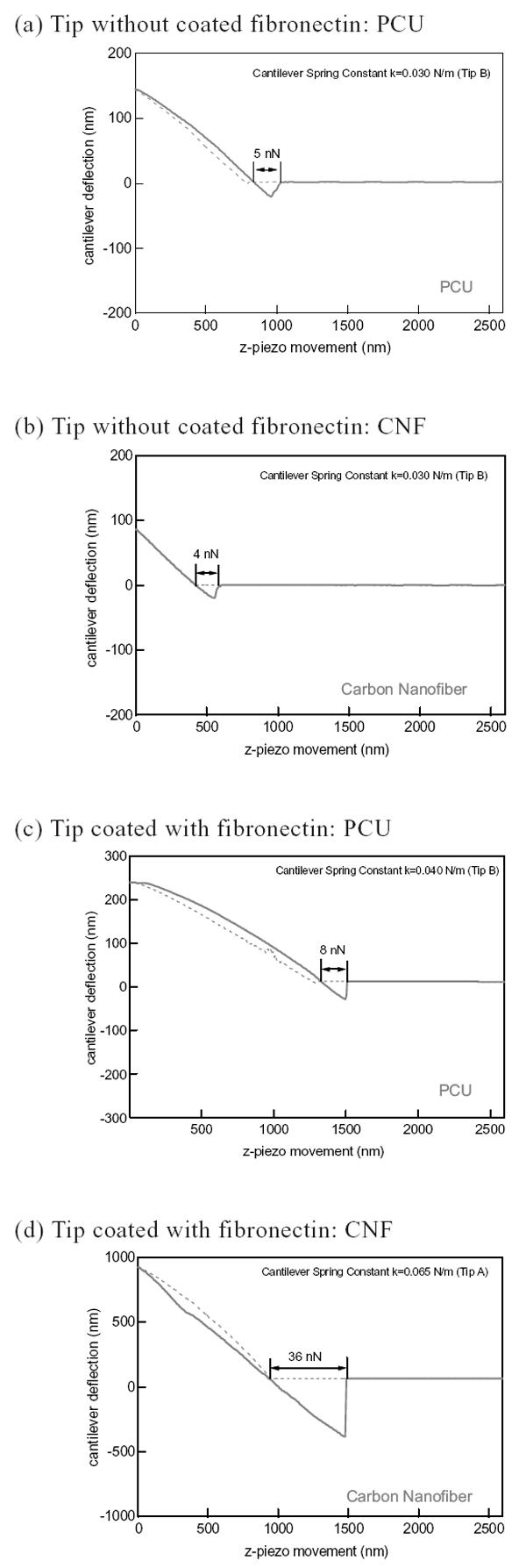
Interaction forces between carbon nanofiber (CNF) and polycarbonate urethane (PCU) without (a and b) and with (c and d) fibronectin-coated tips.
Table 1.
Greater attraction forces (averaged) between an atomic force microscope (AFM) tip coated with fibronectin and carbon nanofiber (CNF) patterns on polycarbonate urethane (PCU)
| PCU – CNF patterned region | Fibronectin attraction force (nN) |
|---|---|
| PCU | 8 |
| CNF | 35 |
Directed calcium phosphate mineral deposition by osteoblasts on CNF patterns on PCU
Adhesion is a prerequisite for osteoblast subsequent functions (such as the synthesis of collagen and deposition of calcium phosphate crystals). For that reason, the present in vitro study determined osteoblast mineral deposition on the substrates of interest for up to 21 days of culture. Results demonstrated directed deposition of calcium phosphate crystals by osteoblasts on CNF patterns on PCU (Figure 8). Upon further examination by EDS, the deposited crystals were identified as calcium phosphate. This result was expected since directed adhesion of osteoblasts occurred along regions of CNF compared with PCU. Thus, it could be expected that calcium phosphate minerals would be deposited along these same regions. This result is significant as it suggests that the microalignment of calcium phosphate crystals that occurs naturally in long bones of the body can be mimicked by aligning CNFs on PCU. Moreover, this study lays the foundation for subsequent studies to use an applied voltage to further promote osteoblast mineral deposition along conductive CNF regions.
Figure 8.
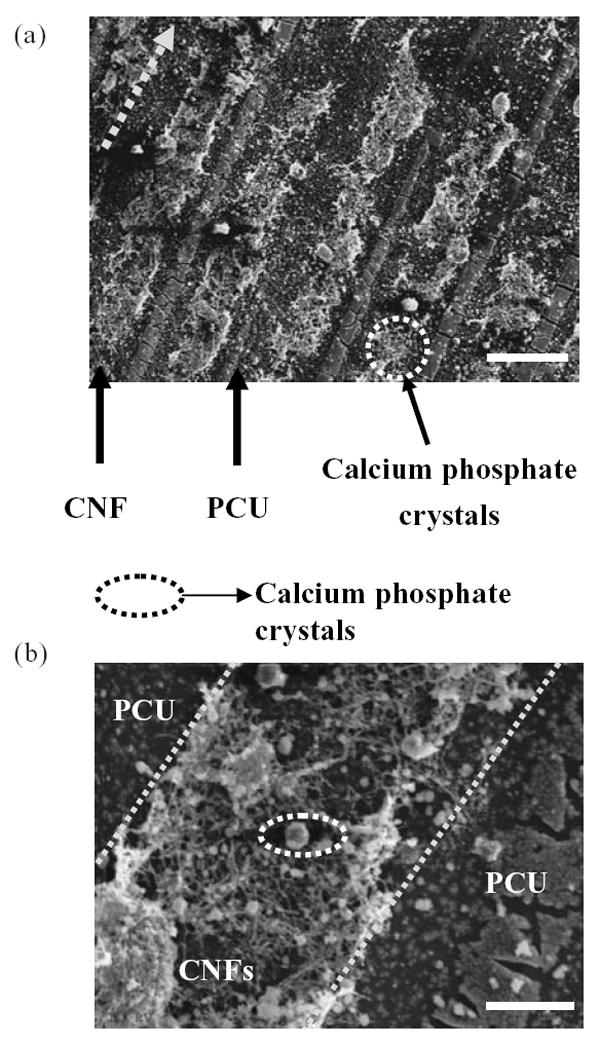
Scanning electron microscopy images of directed osteoblast deposition of calcium phosphate crystals on carbon nanofibers (CNF) patterns on polycarbonate urethane (PCU). Calcium phosphate crystal chemical composition was confirmed by energy-dispersive spectroscopy. Osteoblasts were cultured for 21 days. Bars = 50 μm (a) and 10 μm (b).
Conclusions
Linear, microscale patterns of CNFs on polymer (PCU) surfaces were created in this study. Importantly, selective osteoblast adhesion and cytoskeleton arrangement were observed along CNF patterns in respective matrices. To begin to understand why osteoblast adhesion was directed at CNF regions on PCU, this study also determined higher attraction forces between an AFM tip coated with fibronectin (a protein known to mediate osteoblast adhesion) and patterns of CNF compared with PCU. This result demonstrated the high interactions fibronectin and osteoblasts have with surfaces containing linear patterns of CNF. Moreover, this study showed that the directed osteoblast adhesion translated to enhanced calcium phosphate mineral deposition along linear patterns of CNFs on PCU. In this manner, this study formulated substrates that could be used in future investigations to electrically stimulate osteoblasts residing on CNF regions to efficiently deposit linear patterns of calcium-containing mineral similar to that observed in long bones in the body.
Acknowledgments
The authors thank the National Science Foundation for a Nanoscale Exploratory Research grant (nr 0304521) and Purdue University for a N.F. Andrew Fellowship. The authors thank Dr Jaewon Choi (Intel, Santa Clara, CA, USA) and Mr Youngnam Cho (Department of Chemistry, Purdue University) for valuable insight on fabrication methods. The authors thank Dr Debra M Sherman (Life Science, Purdue University) for SEM images. We also thank Applied Sciences Inc (Cedarville, OH, USA) for the carbon nanofibers used in this study.
References
- [AAOS] American Academy of Orthopaedic Surgeons [online] Accessed April 26, 2005. URL: http://www.aaos.org.
- Elias KL, Price RL, Webster TJ. Enhanced functions of osteoblasts on nanometer diameter carbon fibers. Biomaterials. 2002;23:3279–87. doi: 10.1016/s0142-9612(02)00087-x. [DOI] [PubMed] [Google Scholar]
- Hartgerink JD, Beniash E, Stupp SI. Self-assembly and mineralization of peptide-amphiphile nanofibers. Science. 2001;294:1684–8. doi: 10.1126/science.1063187. [DOI] [PubMed] [Google Scholar]
- Healy KE, Thomas CH, Rezania A, et al. Kinetics of bone cell organization and mineralization on materials with patterned surface chemistry. Biomaterials. 1996;17:195–208. doi: 10.1016/0142-9612(96)85764-4. [DOI] [PubMed] [Google Scholar]
- Kaplan FS, Hayes WC, Keaveny TM, et al. Bone biology. In: Kaplan FS, et al., editors. Orthopedic basic science. Columbus OH: American Academy of Orthopedic Surgeons; 1994. p. 127. [Google Scholar]
- Martin CR, Kohli P. The emerging field of nanotube biotechnology. Nat Rev Drug Discov. 2002;2:29–37. doi: 10.1038/nrd988. [DOI] [PubMed] [Google Scholar]
- McFarland CD, Thomas CH, DeFilippis C, et al. Protein adsorption and cell attachment to patterned surfaces. J Biomed Mater Res. 2000;49:200–10. doi: 10.1002/(sici)1097-4636(200002)49:2<200::aid-jbm7>3.0.co;2-l. [DOI] [PubMed] [Google Scholar]
- Price RL, Waid MC, Haberstroh KM, Webster TJ. Selective bone cell adhesion on formulations containing carbon nanofibers. Biomaterials. 2003;24:1877–87. doi: 10.1016/s0142-9612(02)00609-9. [DOI] [PubMed] [Google Scholar]
- Price RL, Haberstroh KM, Webster TJ. Increased osteoblast viability in the presence of smaller nano-dimensioned carbon fibers. Nanotechnology. 2004;15:892–900. [Google Scholar]
- Price RL, Haberstroh KM, Webster TJ. Select protein interactions increase osteoblast functions on carbon nanofiber based materials. J Biomed Mater Res. 2005 doi: 10.1002/jbm.a.30073. In press. [DOI] [PubMed] [Google Scholar]
- Reif M, Oesterhelt F, Heymann B, et al. Single molecule force spectroscopy on polysaccharides by atomic force microscopy. Science. 1997;275:1295–7. doi: 10.1126/science.275.5304.1295. [DOI] [PubMed] [Google Scholar]
- Supronowicz PR, Ajayan PM, Ullmann KR, et al. Novel current-conducting composite substrates for exposing osteoblasts to alternating current stimuli. J Biomed Mater Res. 2002;59:499–506. doi: 10.1002/jbm.10015. [DOI] [PubMed] [Google Scholar]
- Webster TJ. Nanophase ceramics: the future orthopedic and dental implant material. In: Ying JY, editor. Advances in chemical engineering. Vol. 27. Academic Pr; 2001. pp. 125–66. [Google Scholar]
- Webster TJ, Waid MC, McKenzie JL, et al. Nano-biotechnology: carbon nanofibers as improved neural and orthopedic implants. Nanotechnology. 2003;15:48–54. doi: 10.1088/0957-4484/15/1/009. [DOI] [PubMed] [Google Scholar]