

SUMMARY
In voltage-gated channels, ions flow through a single pore located at the interface between membrane-spanning pore domains from each of four subunits, and the gates of the pore are controlled by four peripheral voltage-sensing domains. In a striking exception, the newly discovered voltage-gated Hv1 proton channels lack a homologous pore domain, leaving the location of the pore unknown. Also unknown are the number of subunits and the mechanism of gating. We find that Hv1 is a dimer and that each subunit contains its own pore and gate, which is controlled by its own voltage sensor. Our experiments show that the cytosolic domain of the channel is necessary and sufficient for dimerization and that the transmembrane part of the channel is functional also when monomerized. The results suggest a mechanism of gating whereby the voltage sensor and gate are one and the same.
Keywords: voltage-sensor, proton current, guanidinium block, voltage-sensitive phosphatase, total internal reflection microscopy, single molecule subunit counting
INTRODUCTION
In most channels made by multiple subunits, permeating ions flow through a single pore located at the central axis of the protein, at the junction of the subunits.(Hille, 2001) However, there are important exceptions, such as the ClC chloride channel and aquaporins, in which the pore is located within each subunit of a dimeric or tetrameric protein, and there are therefore as many pores as subunits (Dutzler et al., 2002; Fu et al., 2000; King et al., 2004; Ludewig et al., 1996; Middleton et al., 1996; Sui et al., 2001). In voltage-gated potassium, sodium and calcium channels four voltage-sensing domains (VSDs) control one permeation pathway that is located at the center of the pore domain (Tombola et al., 2006). In Kv potassium channels the ion permeation pathway lies at the interface between four distinct subunits, and in Nav sodium and Cav calcium channels it lies in an analogous location between four tethered subunits (Long et al., 2005; Yu and Catterall, 2004). One class of voltage-gated channels, the proton channels, long eluded molecular identification. Such channels were first identified in snail neurons more than twenty years ago (Thomas and Meech, 1982). Their biophysical properties and biological role have been elucidated in detail (Decoursey, 2003; DeCoursey et al., 2003), but the cloning of the first member of the family, Hv1 (a.k.a. VSOP), was only accomplished recently (Ramsey et al., 2006; Sasaki et al., 2006). The sequence of Hv1 revealed that the predicted membrane-spanning region consists solely of the VSD, lacking a homologue to the pore domain of other voltage-gated channels (Ramsey et al., 2006; Sasaki et al., 2006).
The number of subunits that make up the Hv1 channel is not known. Unknown are also the number and location of the permeation pathway(s). The lack of a conventional pore domain implies a unique mechanism of gating and of coupling between gate and voltage sensor, but these too are unknown. To address these issues, we set out to determine the number of subunits in Hv1 and to probe the conduction pathway and gating mechanism. We find that Hv1 is a dimer and that each subunit contains its own permeation pathway and gate controlled by a voltage sensor. Our experiments suggest a mechanism of gating for Hv1 channels, which resembles those of the omega pathway recently described in a mutant Shaker potassium channel (Tombola et al., 2007), whereby the voltage sensor also serves as the channel’s gate.
RESULTS
Hv1 is a dimer
To determine the number of subunits present in the Hv1 channel we used a single molecule technique of subunit counting that we recently developed (Ulbrich and Isacoff, 2007). Single-molecule measurements remove ensemble averaging, allowing detection of the behavior of individual molecules, thus providing the frequency distribution of that behavior, rather than just the average behavior of the population, which may blur out distinct properties of discrete sub-populations (Das et al., 2007; Ulbrich and Isacoff, 2007; Weiss, 1999). In our application, single molecule photobleaching of GFPs attached to channel subunits allows us to directly count the number of GFPs, and thus the number of subunits, in channels located on the plasma membrane, their site of function.
The human Hv1 protein (Ramsey et al., 2006) was tagged with GFP at the C-terminus and expressed in Xenopus oocytes at low levels. The GFP-tagged channels were functional and retained the voltage sensitivity of the wild type (WT) channel (Fig. 1E). We visualized the fluorescent channels on the cell surface using total internal reflection fluorescence microscopy (TIRFM). The density of channels was kept low enough to minimize the chance of incidental overlap of two channels within a diffraction-limited spot, yielding 20–200 channels in each field of view (13 µm on a side, Fig. 1A).
Figure 1. Subunit number in the Hv1 channel.
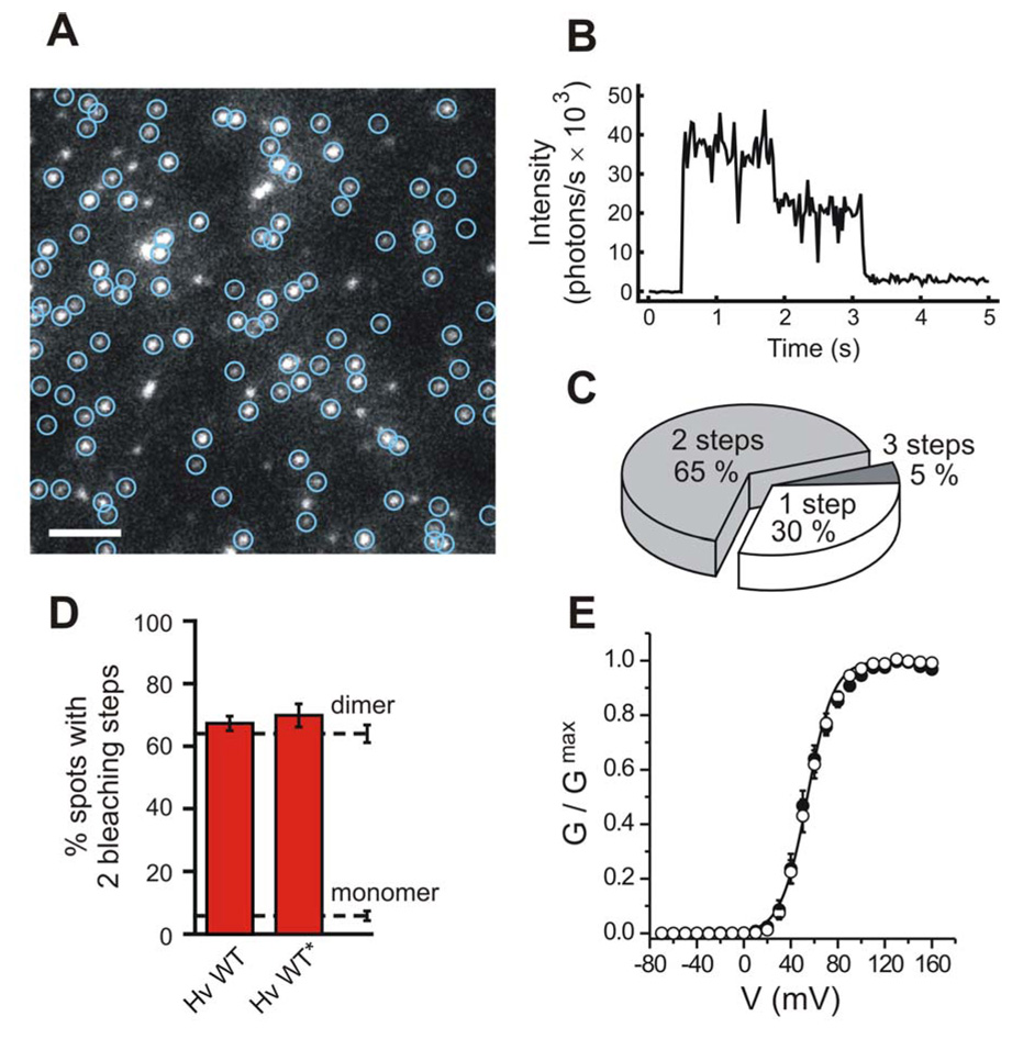
A) Single frame from a representative movie shows GFP-tagged Hv1 channels in the oocyte membrane. Green circles mark immobile spots. White bar indicates 2 µm. B) Two irreversible bleaching steps are visible in the fluorescence intensity trace from a single spot of frame (A). C) Distribution of spots with different numbers of bleaching steps (same movie as in (A)). Of 104 spots, 68, 31 and 5 had two, one and three bleaching steps respectively, consistent with Hv1 being a dimer (see Methods). D) Percentages of fluorescent spots with 2 bleaching steps observed on the plasma membrane of oocytes expressing GFP-tagged Hv1. Asterisk marks construct fused to the Kv1.4 C-terminus to reduce lateral mobility in the membrane. Dashed lines indicate percentages of spots with 2 bleaching steps observed for a channel known to contain 2 GFP-tagged subunits (NMDA receptor, untagged NR1 co-expressed with GFP-tagged NR2B, see Methods) and for a channel known to contain one GFP-tag (Cav2.3 channel, GFP-tagged alpha 1E subunit), hereby serving as references for confirmed dimers and monomers. Error bars are s.e.m. (n = 4 – 14). e) Conductance-versus-voltage relationships for the Hv1-GFP construct with Kv1.4 C-terminus (open circles) and for non-tagged Hv1 (filled circles), determined from tail currents measured in inside-out patches from oocytes. pHi = pHo = 6.0. Error bars are s.e.m (n = 5). The Boltzmann fit for the GFP-tagged channel is also displayed. Fit parameters are reported in Table 2.
Single Hv1 channels were observed as laterally diffusing fluorescent spots. The movement made it difficult to observe multiple bleaching events from the same spot. However, cooling the cells to 4°C reduced the diffusion enabling us to count the number of irreversible steps of photobleaching (Fig. 1B). Since each channel contains as many GFP tags as it does subunits, counting the number of bleaching steps amounts to counting the subunits. The majority of the fluorescent spots from Hv1-GFP channels displayed two bleaching steps (65 ± 3%, n = 11, Fig. 1C). This behavior was similar to what we observed in channels that are known to contain two GFP-tagged subunits (i.e. an NMDA receptor made of 2 NR1 + 2 NR2B-GFP subunits, in which the NR2B subunit was tagged with GFP, and very distinct from what is seen in channels containing only one subunit (a GFP-tagged Cav2.3 α1E channel, which is made of four connected pseudo-subunits, and contains one GFP at its C-terminal end) (Fig. 1D and Table 1). Moreover, this behavior was distinct from channels containing four GFP-labeled subunits, as shown previously (Ulbrich and Isacoff, 2007). The ~1/3 of events with one bleaching step is expected for a pure dimer when one takes into account that ~20% of the GFP tags are non-fluorescent, as observed previously (Ulbrich and Isacoff, 2007) (see Supplementary Information).
Table 1.
| # | Channel | 1 step (%) | 2 steps (%) | 3+ steps (%) | n | avg. # of spots | discarded spots (avg. in %) |
|---|---|---|---|---|---|---|---|
| 1 | NR1 + NR2B-GFP | 36 ± 3 | 63 ± 3 | 1.0 ± 0.7 | 9 | 50 | 9.2 |
| 3 | Hv1 WT w/o Kv1.4C | 33 ± 3 | 65 ± 3 | 2.7 ± 1.1 | 11 | 43 | 10 |
| 2 | Hv1 WT* | 29 ± 4 | 67 ± 3 | 4.3 ± 0.7 | 3 | 105 | 10.5 |
| 4 | NVSP-Hv1* | 60 ± 1.3 | 39 ± 1.4 | 0.7 ± 0.4 | 6 | 52 | 4.4 |
| 5 | Hv1-CVSP* | 97 ± 1.8 | 3.2 ± 1.8 | 0 | 4 | 22 | 8.7 |
| 6 | Hv1-CSh* | 93 ± 2.5 | 7.3 ± 2.5 | 0 | 5 | 34 | 7.3 |
| 7 | NVSP-Hv1-CVSP* | 94 ± 0.7 | 5.9 ± 0.7 | 0 | 7 | 103 | 7.6 |
| 8 | NHv-VSP-CHv* | 49 ± 2.3 | 51 ± 2.3 | 0.7 ± 0.5 | 7 | 39 | 10.1 |
| 9 | Cav2.3α | 94 ± 1.5 | 5.8 ± 1.5 | 0 | 5 | 55 | 7.2 |
constructs #2–8 fused with Kv1.4 C-terminus and coexpressed with PSD-95
The reference channels with a known number of subunits to which we compared Hv1 (the NMDA receptor subunits and the Cav2.3 channel) contain native PDZ binding motifs at their C-termini, which reduce their mobility in the plasma membrane, likely due to interaction with the cell’s PDZ proteins. Therefore, in order to compare Hv1 to these other channels under similar conditions, we also examined Hv1 following fusion of the C-terminus of the potassium channel Kv1.4 to the C-terminus of Hv1-GFP. As expected, fusion of the Kv1.4 C-terminus and co-expression of the synaptic scaffolding protein PSD95 increased the fraction of immobile Hv1 channels. The fraction of spots with 2 bleaching steps remained essentially the same (67 ± 3 %, n = 3) as what we first observed without the added anchoring domain (Fig 1D). This, and our previous result on the voltage-gated phosphatase Ci-VSP (Kohout et al., 2008), demonstrate that the addition of the Kv1.4 C-terminus reduces the mobility, but does not cause aggregation or interfere with oligomer formation. These experiments indicate that Hv1 is made of two subunits.
Block by an adduct at an introduced cysteine and by guanidinium ions
Having found that the Hv1 channel is made of two subunits, we next set out to ask whether there are one or two pores per channel. To find manipulations that block the proton current, we screened for residues in the Hv1 protein that, when substituted by cysteine, make the channel sensitive to block by trimethylaminoethyl-methanethiosulfonate (MTSET), a thiol-modifying reagent that covalently adds a positively charged group to accessible cysteines (Akabas et al., 1992) (Fig. 2). We measured the proton currents of wild-type (WT) and cysteine-substituted channels in inside out patches from oocytes and tested the effect of MTSET added to the intracellular side of the membrane. We found that WT channels are insensitive to intracellular MTSET, while the mutant N214C was almost completely (96 ± 1 %; n = 4) inhibited by MTSET (Fig. 2A, B). The small residual current had the same voltage dependence as before MTSET treatment (Table 2, Fig. 4), consistent with this effect being due to pore block. This observation, coupled with the fact that proteins that contain an arginine at the homologous position (e.g. voltage-gated Na+, K+ and Ca2+ channels, as well as the VSD-containing phosophatase, Ci-VSP) have no proton current (Fig. 2C), suggested that a charged residue at this position is incompatible with proton conduction. We tested this notion by substituting arginine for the native asparagine at this position in Hv1 (N214R) and found that, although GFP-tagged N241R channels reached the cell surface, as gauged by TIRFM, no proton current could be detected (not shown).
Figure 2. Current block in the Hv1 channel.
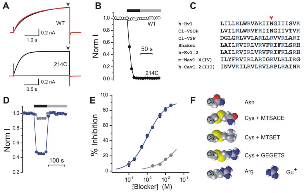
A) Hv1 proton currents elicited by depolarization to +120 mV from a −80 mV holding potential, before (black traces) and after (red traces) MTSET treatment. pHi = 6.0, pHo = 7.5. Upper panel: Hv1 WT. Lower panel: Hv1 N214C. Current at end of depolarization step (black arrowheads) measured as a function of time to generate plots such as (B). B) Changes in normalized proton currents from WT (open circles) and N214C (filled circles) Hv1 channels, as a result of MTSET treatment. Black bar indicates presence of 1mM MTSET in the intracellular solution. Gray bar indicates washout. C) Partial alignment of the S4 segment from the human Hv1 channel and its Ciona Intestinalis homologue Ci-VSOP with corresponding segments from other voltage-gated proteins. D) Reversible block of Hv1 WT by 2 mM guanidinium (blue circles) or ammonium (gray circles). Black bar indicates presence of guanidinium or ammonium in the intracellular solution. Gray bar indicates washout. E) Dose-responses for guanidinium (blue circles) and ammonium (gray circles) block of Hv1. Each point is the average of 4–5 measurements ± s.e.m. F) Cysteine side chain after modification by MTSACE, MTSET and GEGETS compared to guanidinium (Gu+) and to the side chains of asparagine and arginine. The Cα alpha atom of the protein backbone is also displayed. Molecules shown as space filling CPK scheme.
Table 2.
| # | Channel | V1/2 (mV) | kT/zeo (mV) | n* |
|---|---|---|---|---|
| 1 | Hv1 WT | 53 ± 3 | 11.6 ± 0.6 | 5 |
| 2 | Hv1 GFP-tagged | 54 ± 3 | 11.1 ± 0.4 | 5 |
| 3 | TD WT-WT | 47 ± 2 | 12.6 ± 0.6 | 4 |
| 4 | NVSP-Hv-CVSP | 68 ± 2 | 15.0 ± 0.2 | 6 |
| 5 | TD WT-214C | 45 ± 1 | 14.9 ± 0.8 | 4 |
| 6 | TD WT-214C after MTSET | 51 ± 4 | 11.3 ± 1.2 | 4 |
| 7 | TD 214C-214C | 43 ± 1 | 14.3 ± 0.6 | 4 |
| 8 | TD 214C-214C after MTSET | 48 ± 3 | 12.0 ± 0.8 | 4 |
number of oocytes
Figure 4. Effect of MTS modification on gating of homo- and heterodimeric Hv1.
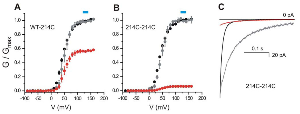
A–B) Normalized G-V plots for the tandem dimers WT-214C (A) and 214C-214C (B) before (black circles) and after (gray circles) MTSET treatment. Red circles represent the G-Vs after MTS modification normalized to the Gmax before modification (i.e. showing the reduction in conductance due to MTS). Each point is the average of 4 measurements ± sem. Error bars not shown when smaller than symbols. The G-Vs were fitted with the Boltzmann equation as explained in the Methods. The parameters of the fit are given in Table 2. Blue boxes indicate the voltages used to monitor the effect of MTS reagents on the proton currents of the different linked and un-linked Hv1 dimers. C) Example of kinetics of deactivation of tandem dimer 214C-214C before (black) and after (red) MTSET treatment. Tail currents recorded at −80 mV after depolarization at +140mV (pHi = pHo = 6.0, see Methods for details). Modification of position 214C reduces the size of the tail current and slows down channel deactivation. The gray trace is the tail current after modification scaled to match the initial value before modification. MTSET modification of 214C slows down also the kinetics of activation (not shown).
We next reasoned that, if the positively charged guanidinium group of the arginine side chain is what blocks the proton current in Hv1(N214R), as the first S4 arginine has been shown to block the omega current through the Shaker and Nav1.2 channel VSDs (Sokolov et al., 2005; Starace and Bezanilla, 2004; Tombola et al., 2005), then soluble guanidinium might act as a blocker of Hv1. Indeed, we found that intracellular guanidinium reversibly blocked Hv1 with a Kd of 1.05 ± 0.07 mM, %inhib(max)= 92 ± 2, and a Hill coefficient of 0.91 ± 0.04 (n=5, Fig. 2D, E). The Hill coefficient of approximately one suggests that one guanidinium ion is sufficient to block the pore of Hv1. Ammonium, the smaller positively charged group of the lysine side chain, also blocked the Hv1 current, but less effectively (Fig. 2D, E).
Each Hv1 subunit contains one pore
We constructed a tandem dimer of Hv1 that would allow us to independently manipulate the two subunits constituting the channel by mutagenesis. In case the channel has one central pore, manipulations that block the proton flow when made in both subunits, would also change the conduction properties of the common pore when made in only one of the two subunits, although likely to a lesser extent. If the protein contains two separate pores, then we would expect two possible scenarios depending on whether the perturbation remains confined to the manipulated (mutant) subunit or whether it also propagates to the non-manipulated (WT) subunit. In the scenario of confined perturbation, we expected the block of the pore in the mutant subunit to leave unaltered the proton flow through the WT subunit. This scenario is clearly different from the case of one pore per dimer where modification of either one or both subunits causes alterations in the proton flow through the common pore. In the scenario of propagating perturbation, we expected the block of the pore in the mutant subunit to be accompanied by a change in the proton flow through the WT subunit producing results similar to the case of one pore per channel. Thus, a lack of effect of the pore-blocking manipulation in one subunit on half the current flow would argue for the presence of a second and separate pore in the wild type subunit, which is not affected by the manipulation of the mutant subunit (non-propagating perturbation).
We constructed the tandem dimers by connecting the C-terminus of one Hv1 subunit to the N-terminus of a second Hv1 subunit via a 17-aa-long flexible linker (Fig. 3A, Methods). We refer to the linkage of two WT subunits as the WT-WT dimer. We then generated tandem dimers in which one or both subunits contained the N214C substitution, which we had shown to be subject to modification by MTSET, yielding WT-214C, 214C-WT and 214C-214C. We reasoned that if each Hv1 subunit has one pore then MTSET should block two pores in 214C-214C, one pore in WT-214C and 214-C-WT, and none in WT-WT. In addition, if after MTSET block, WT-214C and 214C-WT still have one functioning WT pore, the inhibition by guanidinium of the proton current carried by this unmodified pore should be the same as the inhibition of the WT channel. On the other hand, if two subunits are needed to form a single Hv1 pore, then MTSET should block it not only in 214C-214C, but also in WT-214C and 214C-WT. Such block of a common pore by two MTSET molecules in 214C-214C would be near complete, while block by one MTSET of WT-214C and 214C-WT may be only a fraction of the block of 214C-214C (Fig. 3A). Such fractional block would be unlikely to be the same for different MTS reagents, which have different side chain volumes and charge (Fig. 2F).
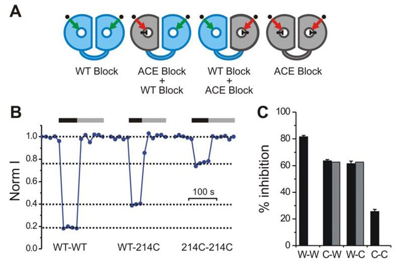
Figure 3. Block of homo- and heterodimeric Hv1 by different thiol-reactive agents.
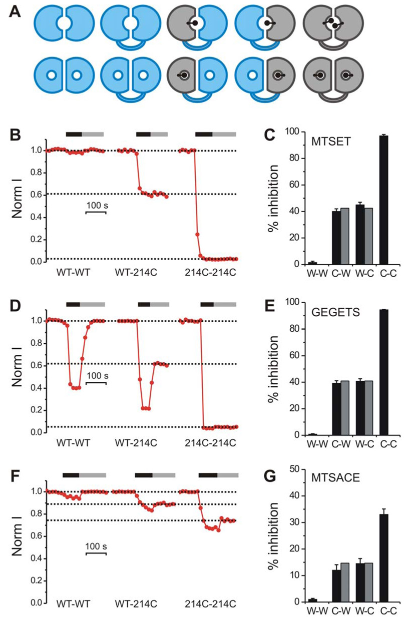
A) Two possible scenarios for the structural organizations of the Hv1 permeation pathway: (i) one pore per dimer (upper row) and (ii) two pores per dimer (lower row). WT subunit shown in blue, N214C subunit shown in gray. Linked dimers with defined stoichiometry shown after cysteine modification (black dots). B–G) Inhibition of proton current in tandem dimers WT-WT (W-W), WT-N214C (W-C), N214C-WT (C-W), and N214C-N214C (C-C) after treatment with thiol-reactive agents: MTSET (B) & (C), GEGETS (D) & (E), MTSACE (F) & (G). Black and gray horizontal bars in (B), (D) and (F) indicate presence of 1mM thiol-reactive agent in the intracellular solution and wash out respectively. Currents were measured at +120 mV. pHi = 6.0, pHo = 7.5. Note that in addition to their irreversible block due to cysteine modification, GEGETS and MTSACE also produce a reversible block, although this is more prominent for GEGETS, consistent with the fact that GEGETS contains two guanidinium groups and with the reversible block by guanidinium. In the histograms in (C), (E) and (G) each black bar is the average inhibition from 4–6 patches. Error bars are ± s.e.m. Gray bars indicate inhibition of heterodimeric channels calculated from the inhibition of homomeric channels as explained in the text.
MTS modification of 214C-214C, WT-214C and 214C-WT blocked the proton current (Fig. 3) with little effect on the voltage dependence of channel activation (Fig. 4A, B), enabling us to monitor block with repeated steps to a single voltage at the top of the conductance-voltage relations before and after MTS treatment (Fig. 4A, B). As shown in Figure 3 (panels B and C), MTSET modification blocked 214C-214C almost completely (similar to block of channels formed by expression of the unlinked 214C), blocked WT-214C and 214C-WT by ~40 %, and did not block WT-WT at all. The 2-pore model would predict that the ~60% residual current in the WT-214C and 214C-WT would flow almost entirely through the WT subunit, since the 214C-subunit would be almost completely blocked by the MTSET. We tested this prediction by following MTSET exposure with exposure to 10 mM guanidinium. The block by 10 mM guanidinium of the residual current following MTSET treatment in the two linked heterodimers, WT-214C and 214C-WT, was 81.0±0.4% (n=4) and 80.4±1.3% (n=4), respectively. This degree of guanidinium block is indistinguishable from the guanidinium block of the linked homodimeric WT-WT channel (79.8±0.5%, n=4) and the channel formed by the unlinked monomeric WT subunit (81.2±2.4%, n=4), consistent with the idea that the linked heterodimer contains two separate pores: one WT pore and one N214C pore, with the N214C pore being completely blocked by MTSET, thus leaving the residual current to flow through the WT pore, which displays the typical WT block by guanidinium.
If the WT and N214C subunits had pores with the same conductance, then the MTSET block of the linked heterodimer would have been 50%. We found that the block was actually ~40%, suggesting that the N214C subunit’s pore has a conductance that is ~25% smaller than the WT subunit (see Methods). We next tested the two-pore model in a way that does not depend on the relative conductances of the WT and N214C pores.
If there are two separate pores in the dimer, as suggested above, then the inhibition of WT-214C and 214C-WT is expected to be a fraction of the inhibition of 214C-214C, and this fraction should be the same for all MTS reagents, regardless of their chemical properties and differences in the degree block that they induce on 214C. Having found that block by MTSET of WT-214C and 214C-WT is ~40% of the block of 214C-214C, we next tested two other thiol-modifying reagents: guanidinoethyl-guanidinoethanethiosulfonate (GEGETS), and aminocarbonylethyl-methanethysulfonate (MTSACE). GEGETS attaches to the cysteine a group that resembles an arginine side chain, with a positive charge carried by a guanidinium group, while MTSACE attaches an uncharged group that resembles the original asparagine side chain present at position 214 in WT (Fig. 2F).
We found that 214C-214C was fully blocked by GEGETS, and that the inhibition of WT-214C and 214C-WT was 40.7 ± 2.0 % (n=6) and 39.2 ± 2.0 % (n=5), respectively (Fig. 3D, E), very similar to what was seen for MTSET modification (Fig. C). On the other hand, MTSACE produced only a partial block of 33 ± 2.1 % (n =5) of the 214C-214C homodimer, and the block of the two heterodimers WT-214C and 214C-WT was 14.5 ± 1.9 % (n=6) and 12.1 ± 2.1 % (n=6) respectively, i.e. once again ~40% of the block of 214C-214C (Fig. 3F, G). These findings provide further support for the idea that there are two separate pores in each Hv1 dimer.
In a third test of the 2-pore model we considered the following. Since both MTS modification of 214C and intracellular guanidinium block the proton pore, we reasoned that conjugation of an MTS reagent that only partly blocks conduction, such as MTSACE, would alter block by guanidinium in a detectable manner. As shown in Figure 5 (panels B and C), we found that after MTSACE exposure, 10 mM guanidinium blocked the WT-WT channel by 80%, the same degree of block as seen without MTSACE exposure, i.e. as expected for the unmodified pore. In contrast, following MTSACE treatment, the block by 10 mM guanidinium of homodimeric 214C-214C was only 25%. Whether this lowering of apparent guanidinium affinity by MTSACE modification at 214C reflects interaction with guanidinium in the pore or an allosteric effect of MTSACE conjugation on guanidinium binding (Supplementary Fig. 1), it enabled us to test the 2-pore model in the following way.
Figure 5. Guanidinium block of homo- and heterodimeric Hv1 pretreated with MTSACE.
A) Schematics indicating expected inhibition of MTSACE-modified channels by guanidinium in homo- and heterodimeric Hv1. Black knob in pore of gray subunits (N214C) indicates partial block by MTSACE. Channel modification by MTSACE reduces guanidinium affinity (ACE block). B–C) Reversible guanidinium block of the proton currents from the indicated linked dimers pretreated with MTSACE. Black and gray horizontal bars in (B) indicate presence of 10 mM intracellular guanidinium and wash out respectively. Currents were measured at +120 mV. pHi = 6.0, pHo = 7.5. In the histogram in (C) each black bar is the average inhibition by 10 mM guanidinium from 4–6 patches. Error bars are ± s.e.m. Gray bars indicate inhibition of heterodimeric channels calculated from the inhibition of homomeric channels (see text).
The effect of MTSACE conjugation on guanidinium block for the 2-pore model predicts that the residual current through WT-214C and 214C-WT, following modification by MTSACE, would undergo guanidinium block that would be a combination of the 80% block typical of the WT pore and the 25% block that we had demonstrated for the MTSACE-conjugated 214C pore, adjusted for the relative contributions of the two pores to the proton current (see Methods). Our results were consistent with there being two pores per dimer, one of which is partially blocked by MTSACE (214C) and therefore has a reduced guanidinium affinity, and the other of which (WT) is fully conducting (no MTSACE) and has a normal affinity for guanidinium (Fig. 5C). The results were not consistent with the single pore model in which MTSACE treatment would be expected to change guanidinium block even if only one subunit contains 214C conjugated to MTSACE (Supplementary Fig. 1).
In summary, three lines of evidence point to a 2-pore construction of the Hv1 dimer, with one pore in each subunit: 1) The high similarity in the degree of block by a variety of distinct MTS reagents of the heterodimeric WT-214C and 214C-WT constructs compared to the block of the 214C-214C homodimer, despite the differences in the steric and electrostatic properties of the MTS reagents, consistent with block of two separate pores and unlikely for additive effects of two MTS reagents binding in a common pore; 2) When MTSET is used, which completely blocks 214C, then further block by guanidinium of WT-214C and 214C-WT follows exactly what would be expected for block of the separate WT pore; and 3) In contrast to (2), when MTSACE is used, which only produces partial block of 214C, then the 214C subunit continues to conduct most of its current and guanidinium block of WT-214C and 214C-WT follows the predicted combination of normal block of the WT pore and reduced block of the 214C-MTSACE pore, with the degree of block quantitatively matching the prediction for two separate pores.
The Hv1 cytoplasmic domain is necessary for dimer formation
The above findings led us to ask which parts of Hv1 mediate the dimerization. We recently found that the Hv-related VSD-containing protein Ci-VSP (Murata et al., 2005) exists in the membrane as a monomer (Kohout et al., 2008). We reasoned that by making chimeric proteins between Hv1 and Ci-VSP, we could identify the region of Hv1 responsible for dimerization. In both oligomeric channels with a single inter-subunit pore, and in oligomeric channels with multiple pores, interactions between the transmembrane portions of adjacent subunits and interaction between cytoplasmic domains contribute to assembly (Hille, 2001). We replaced the cytosolic N- and/or C- termini or the transmembrane domain of Hv1 with the corresponding parts of Ci-VSP producing four different chimeric proteins: i) NVSP-Hv, ii) Hv-CVSP, iii) NVSP-Hv-CVSP and iv) NHv-VSP-CHv (See Methods). In a fifth chimera, Hv-CSh, we replaced the C-terminus of Hv1 with the C-terminus of Shaker. We expressed GFP-tagged versions of these chimeras in oocytes and counted the subunits (Fig. 6A, B), as done above.
Figure 6. Monomeric and dimeric chimeras from Hv1 and Ci-VSP.
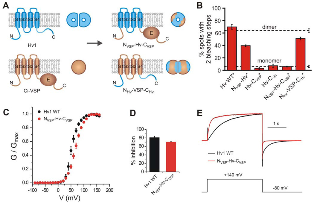
A) Cartoon showing the monomeric chimera in which the N- and C- termini of Ci-VSP are transplanted into the Hv1 channel (upper panel, NVSP-Hv-CVSP), and the dimeric chimera in which the N- and C-termini of Hv1 are transplanted in Ci-VSP (lower panel, NHv-VSP-CHv). B) Percentages of fluorescent spots with 2 bleaching steps observed on the plasma membrane of oocytes expressing the GFP-tagged chimeras: NVSP-Hv, Hv-CVSP, Hv-CSh, NVSP-Hv-CVSP and NHv-VSP-CHv compared to the percentages for GFP-tagged Hv1 WT. Asterisks mark constructs fused to the Kv1.4 C-terminus to reduce lateral mobility in the membrane. Error bars are s.e.m. (n = 4 – 14). As in Figure 1D, dashed lines indicate percentages of spots with 2 bleaching steps observed for a channel known to contain 2 GFP-tagged subunits (reference dimer) and for a channel known to contain one GFP-tag (reference monomer). C) G-V of NVSP-Hv-CVSP chimera compared to Hv1 WT. Average of 6 measurements ± sem. Parameters of the Boltzmann fit are reported in Table 2. D) Extent of block of NVSP-Hv-CVSP and Hv1 WT by 10 mM intracellular guanidinium (± sem, n=4, pHi=6.0, pHo=7.5). E) Examples of activation and deactivation of NVSP-Hv-CVSP and Hv1 WT. Proton currents were scaled to have the same value at +140 mV.
After counting the numbers of fluorescent spots with one and two bleaching steps in the chimeric proteins, we compared these observations to the reference two-GFP containing NMDA receptor (tagged only on NR2B) and the reference one-GFP-tagged Cav2.3 channel. We found that Hv-CVSP and Hv-CSh almost always bleached in a single step, similar to the reference monomer, and that NVSP-Hv dimerized at a lowered efficiency, intermediate between the reference dimer and the reference monomer (Fig. 6B). These results suggest that the transmembrane domain plays little or no role in dimerization, while the N and C-termini play an important role. To test the idea further, we asked whether the Hv1 N and C-termini could make the normally monomeric Ci-VSP into a dimer. Indeed, we found that the NHv-VSP-CHv chimera dimerizes almost as well as does the native Hv1 (Fig. 6B). The results indicate that the N and C-termini of Hv1 are both necessary and sufficient to induce dimerization.
The gate in each subunit is operated by one voltage sensor
Having found that Hv1 is a dimer and that each subunit contains its own pore, we wondered if the monomeric chimeras would function. We therefore investigated the function of the NVSP-Hv-CVSP chimera, which contains the Hv1 transmembrane domain, but is monomeric because it lacks the Hv1 N and C-terminal dimerization domains (Fig. 6B). We found that this monomeric version of the Hv1 VSD functions as a voltage-gated channel (Fig. 6C–E), providing a strong fourth line of evidence that each subunit of Hv1 contains a pore of its own.
The kinetics of opening and closing for the monomeric NVSP-Hv-CVSP chimera was found to be faster than the opening and closing kinetics of the WT dimeric channel (Fig. 6E). In addition, the G-V of the chimera was ~30% less steep than the G-V of WT (Table 2, Fig. 6C). Despite these differences between the monomeric NVSP-Hv-CVSP chimeric channel and the WT channel, the finding that one Hv1 subunit on its own behaves as a voltage-gated channel shows that each pore in the dimeric Hv1 has its own gate controlled by one voltage sensor, which is located in that subunit.
DISCUSSION
Hv1 is a dimer, with dimerization driven by the cytoplasmic domain
We used a single molecule technique (Ulbrich and Isacoff, 2007) to visualize GFP-tagged Hv1 channels on the cell surface with TIRFM. The advantages of this method are that it focuses exclusively on the plasma membrane, where channels reach only after they have undergone the quality control processes of membrane targeting and the site of channel function, and that subunit stoichiometry is assessed for individual proteins, rather than via bulk methods, which may not detect heterogeneity from average behaviors.
We determined the number of subunits per channel by counting the number of photo-bleaching events from channels that were expressed at a sufficiently low density to insure that practically all of the fluorescent spots on the cell surface corresponded to individual proteins. We tested both WT Hv1 channels, tagged with GFP, and ones whose mobility was reduced by an additional PDZ-interaction domain and co-expression of the PDZ protein PSD95. In both cases, the fraction of fluorescent spots that bleached in two steps was very similar to what was seen in a known reference—NMDA receptors tagged with GFP on only two of the four subunits—and clearly differed from two other references, one that carries a single GFP per channel and one that carries four GFPs per channel (Ulbrich and Isacoff, 2007).
Chimeras between Hv1 and the voltage-dependent phosphatase Ci-VSP, which was recently shown to be monomeric (Kohout et al., 2008), or the C-terminal of the Shaker Kv1 channel, showed that dimerization depends on the cytoplasmic domain, and not the membrane domain, of Hv1. The evidence for this was that substitution of the N-terminal of Hv1 was found to compromise dimerization, and substitution of the C-terminus was found to disrupt it completely, while transplantation of the two terminals from Hv1 onto membrane domain of Ci-VSP was sufficient to dimerize the normally monomeric Ci-VSP.
Each Hv1 subunit contains a pore
Having found that the Hv1 channel is made of two subunits, we asked whether there are one or two pores per channel. We identified a site in Hv1, N214, that when mutated to cysteine makes the channel susceptible to block by the thiol-reactive MTS reagents, enabling us to modify the conduction pathway. We then constructed tandem dimers of Hv1 that would allow us to independently introduce the N214C mutation into the two subunits. Channels formed by the linked homodimers, WT-WT or 214C-214C, were the same as those formed by the free co-assembly of unlinked WT or 214C subunits, respectively, enabling the analysis. We also found that the WT channel is blocked by free guanidinium, providing a second blocking probe of the pore. We then tested the expectation that only if the channel has two pores, a separate one in each of its two subunits, would manipulation in one subunit leave unaffected the flow through the unmutated pore.
Three lines of evidence pointed to a 2-pore construction of the Hv1 dimer, with one pore in each subunit: 1) The similarity of the fractional block of the heterodimeric WT-214C and 214C-WT constructs compared to that of the 214C-214C homodimer by different MTS reagents with distinct steric and electrostatic properties, 2) When MTSET completely blocks 214C, then further block by guanidinium of WT-214C and 214C-WT follows exactly what would be expected for block of a separate WT pore; and 3) When MTSACE partially blocks 214C then guanidinium block of WT-214C and 214C-WT follows the predicted combination of normal block of the WT pore and reduced block of a separate 214C-MTSACE pore. A fourth line of evidence also showed that each subunit has its own pore, when we found that the monomerized Hv1 chimera, NVSP-Hv-CVSP, functions as a voltage-gated proton channel. These findings argue strongly that the Hv1 dimer contains two separate pores.
The finding that Hv1 can function as a monomer suggests that dimerization might endow the channel with a favorable property, such as the steeper voltage dependence or the slower gating kinetics that we observe, which may match proton flux to electron transport during the oxidative burst (DeCoursey et al., 2003). In addition, the VSDs of voltage-gated Na+, K+, and Ca2+ channels undergo cooperative conformational changes in order to open the gate in the pore domain (Tombola et al., 2006). Analogous subunit interactions could take place in Hv1. If the C-termini of the two subunits associate in the dimer, as implied by our findings, the S4 helices in the two subunits could be forced to stay close enough to one another to influence each other’s movements. The cytosolic multimerization domain may have other functions too. It may, as in K+ channels, require multimerization in order to bind accessory subunits, or it may contain trafficking signals that are selectively hidden or exposed by dimerization. Further work is required to address these questions.
Model of the permeation pathway and the mechanism of voltage dependent gating
Our evidence that Hv1 is a dimer containing two separate pores in the two subunits raises questions about where the permeation pathway lies and how the voltage sensor controls the gate of each of the pores. The finding that the proton pore in one subunit can work in the absence of the other subunit makes the location for the pore at the protein interface between the two subunits very unlikely. We considered that the pore could lie at the lipid-protein interface, or, alternatively, that it could lie in the heart of the subunit. The second model is particularly attractive, since there are two precedents for ion conduction pathways within the core of a VSD.
We recently described a metal-cation-selective pore—the omega pore—that opens in the VSD of the Shaker voltage-gated K+ channel when the first S4 arginine (R1) is mutated to a smaller uncharged amino acid and the channel is in the resting conformation at negative voltage (Tombola et al., 2007; Tombola et al., 2005). A similar omega pore has been described in mutant voltage-gated Na+ channels (Sokolov et al., 2005; Sokolov et al., 2007). Proton pores have also been described in the Shaker VSD with histidine substitutions R1H or R4H (Starace and Bezanilla, 2004; Starace et al., 1997). What is the relationship between these omega/proton pores in K+ and Na+ channels and the proton pore of the Hv1 channel? Our study of Hv1 reveals intriguing similarities between these VSD pores.
Asparagine 214 (N214) of the WT Hv1 channel aligns with the fourth S4 arginine (R4) of the Shaker channel (Fig. 2C). While, as shown above (Fig. 2–Fig. 5), replacement of N214 with cysteine yields conducting channels, we found that replacement of N214 with arginine abolishes the proton current. In Shaker, the nature of the side chains at the R1 position determines the size of the omega current (Tombola et al., 2005) and when R1 is substituted by a histidine the omega pore becomes proton selective (Starace and Bezanilla, 2004). In Hv1, N214C can react with thiol-modifying agents in the intracellular solution, consistent with the internal exposure of R4 and positions around it in the Shaker K+ and in Na+ channel (Larsson et al., 1996; Yang et al., 1996). The omega pathway opens when the membrane potential is negative and the VSD reaches its resting conformation (Campos et al., 2007; Durell et al., 2004; Pathak et al., 2007; Tombola et al., 2007; Yarov-Yarovoy et al., 2006) (S4 “down”). This places the R1 position in the middle of the membrane electric field (Gandhi and Isacoff, 2002; Larsson et al., 1996; Yang et al., 1996), corresponding to the narrowest portion of the omega pore (Tombola et al., 2007). Alternatively, depolarization of Shaker moves the R4 position to the middle of the membrane electric field (S4 “up”) to replace R1 (Gandhi and Isacoff, 2002; Larsson et al., 1996) and under these conditions the R4H mutant of Shaker opens and conducts protons (Starace et al., 1997). In Hv1, the proton pore opens at positive voltages (S4 “up”), consistent with the residue at position R4, i.e. asparagine 214, entering a location in the narrowest part of the VSD pathway and enabling protons to pass. In support of this model, both substitution of N214 with arginine and modification of N214C with MTS reagents block the Hv1 pore.
Based on these similarities between voltage-gated currents of the Hv1 VSD and the voltage-gated omega/proton pores in the VSDs of the Shaker K+ channel and Na+ channels, we propose that the mechanism of gating of the Hv1 channel is similar to that of the omega/proton pores in other voltage gated channels, where gating in Hv1 occurs via S4 movement into a conformation that lets protons pass through the VSD only in the “up” state by placing a small polar residue into the pathway otherwise occupied, and blocked, by large positively charged arginine residues.
To explain the high energy barrier that protons have to overcome to permeate voltage-gated proton channels, DeCoursey and Cherny (1998) proposed that the rate-limiting step for proton permeation is not diffusion to the mouth of the channel but proton transfer in a narrow region of the permeation pathway. The existence of a constriction in the VSD permeation pathway can provide a simple explanation for why guanidinium ions added intracellularly block the proton channel. The constriction that prevents guanidinium permeation in Hv1 may be the selectivity filter for protons. Further studies will be needed to pinpoint the selectivity filter and to determine the contribution of the side chain at the “R4” position to the proton permeation pathway.
Conclusion
In conclusion, using a single molecule optical method that we recently developed we find that, in contrast to the classical tetrameric voltage-gated channels and to the monomeric Ci-VSP, the Hv1 proton channel is a dimer. We find that each of the subunits has its own permeation pathway, which is likely to be situated in the heart of the VSD. Similar to the omega pathway of the Kv VSD, each of the Hv1 permeation pathways has its own gate controlled by one voltage sensor. The dimerization in Hv1 depends on the cytosolic domain of the channel (Fig. 7).
Figure 7. Tetrameric omega-conducting Shaker potassium channel compared to the dimeric Hv1 channel and the monomeric chimera NVSP-Hv-CVSP.
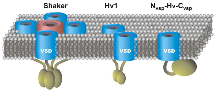
VSDs are blue and the pore domain of Shaker is pink. Intracellular domains are dark yellow. In Hv1 and Shaker the intracellular domains are important for oligomerization. The intracellular domain of Ci-VSP is a lipid phosphatase. The ability of the VSD of Shaker and Hv1 to conduct ions or protons depends on the presence of neutral residues at key positions in the S4 segment (see text). Ci-VSP WT does not conduct protons or solution ions, but the NVSP-Hv-CVSP chimera conducts protons.
Our findings are consistent with a single ion channel domain combining two functions that are separate in most other channels, those of input and output, by serving as both a sensor and a gate. This represents a unique solution to the coupling problem. As suggested by earlier work (Jiang et al., 2003; Murata et al., 2005; Ramsey et al., 2006; Sakai et al., 2001; Sasaki et al., 2006) our findings also demonstrate that VSDs, on their own, without a pore domain to lean on, can orient in the membrane, undergo functional rearrangements and interact, providing new insight into how they function in the classical channels that generate the action potential and in the new class of voltage-gated enzymes.
METHODS
DNA constructs for Hv1, CiVSP chimeras, and tandem dimers
The cDNA for the human Hv1 channel was kindly provided by David Clapham (Ramsey et al., 2006), and the cDNA for Ci-VSP was a gift from Yasushi Okamura (Murata et al., 2005). The PSD-95 DNA was kindly provided by Peter Scheiffele. We subcloned Hv1 into the vector pGEMHE for expression in Xenopus oocyte. All DNA constructs were made using standard cloning techniques and were confirmed by DNA sequencing. We fused monomeric EGFP (mEGFP) to the C-terminus of Hv1 using a short linker with the amino acid (aa) sequence GGSGGSRGSGGSGG. For the constructs containing the C-terminus of Kv1.4, we used the linker SRGTSGGSGGSRGSGGSGG between Hv1 (or the chimera constructs with Ci-VSP) and mEGFP and fused the 69 C-terminal aa of Kv1.4 to the end of mEGFP. For the generation of the chimera constructs, we used the SOEing technique (Horton et al., 1990). In the constructs containing parts of Ci-VSP, aa 1–96 of Hv1 were replaced by aa 1–113 of Ci-VSP for the chimeras containing the N-terminal Ci-VSP, aa 97–227 of Hv1 were replaced by aa 114–239 of Ci-VSP for the chimeras containing the transmembrane domain of Ci-VSP, and aa 228–273 of Hv1 were replaced by aa 240–576 of Ci-VSP or aa 490–656 of Shaker H4 for the chimeras containing C-terminal Ci-VSP or Shaker, respectively. For the chimera of Hv1 with Shaker, we started from the Hv1-mEGFP construct without the Kv1.4 C-terminus because Shaker already contains a PDZ binding motif at its C-terminus that is very similar to that of Kv1.4. For the other chimeric constructs we started from the Hv1-mEGFP-Kv1.4C fusion. The tandem dimer of Hv1 contained a 17-aa long linker between the two Hv1 monomers with the sequence GGSGGSGGSGGSGGSGG. First two constructs were generated, each containing one copy of Hv1 and either the first half of the linker at the N-terminus or the second half at the C-terminus. After introduction of the mutations, the first copy was ligated into the plasmid containing the second copy, reconstituting the full linker between the two copies.
Expression in Xenopus oocytes
RNA was transcribed from NheI- or SphI-linearized DNA using the T7 mMessage mMachine Kit (Ambion), and correct size of the transcript was confirmed by gel electrophoresis. For the single-molecule photobleaching experiments, 50 nl of 0.01–0.02 µg/µl of RNA of Hv1 or one of the chimeras were injected into Xenopus laevis oocytes. When PSD-95 was coexpressed, 0.25µg/µl PSD-95 RNA was added to the injected RNA solution. For the electrophysiological measurements 50 nl of RNA 0.5–1.5 µg/µl were injected. Cells were maintained in medium (ND96) containing 96 mM NaCl, 2 mM KCl, 1.8 mM CaCl2, 1 mM MgCl2, 10 mM Hepes, 5 mM pyruvate, 100 mg/L gentamycin, pH 7.2. Expression of protein at 12°C was allowed for 12–18h before the start of the photobleaching experiments. For electrophysiological measurements, expression at 18°C was allowed for 1–3 days.
Single-molecule TIRF imaging and subunit counting
12–18h after RNA injection, Xenopus oocytes were treated enzymatically with neuraminidase and hyaluronidase, devitellinized manually and placed on a high refractive index coverslip (n=1.78) that matched the refractive index of the objective lens (Olympus 100x/NA 1.65). GFP was excited with a 488nm Ar laser, emission was recorded through a 525/50 bandpass filter (Chroma) with a EMCCD camera (Andor Ixon DV-897 BV) and movies of 500 frames were acquired with 30–50 frames per second. The channels with fused GFP appeared as fluorescent spots with diffraction-limited diameter (200–250nm). Fluorescent spots that stayed immobile (movement <2 pixels = 100 nm) during the movie were selected, and the emission intensities of these spots were extracted for each frame of the movie. We manually counted the number of bleaching steps for each trace, and discarded traces that showed irregular emission intensities without discrete levels and so could not be analyzed (Ulbrich and Isacoff, 2007). The steps within each single trace were of similar amplitude, but varied between different traces due to the different distances of the protein from the coverslip and therefore different illumination intensities in the evanescent field. The fractions of fluorescent spots with 1, 2 or more bleaching steps and discarded spots are shown in Supplementary Table 1. In some experiments we counted a few traces with 3 or more bleaching steps (less than 5%). Blinking of GFP was observed in a small number of traces (<3 for each experiment), but did not interfere with counting of bleaching steps because after blinking the fluorescence intensity returned to the same level as before. In some cases, we observed a small residual fluorescence or a slowly bleaching background. A selection of example traces for 1 and 2 bleaching step events and for discarded traces is presented in Supplementary Figure 2.
Immobilization of Hv1 at the plasma membrane
In our initial single molecule photobleachnig experiments with Hv1-mEGFP we observed considerable movement of the fluorescent spots (lateral diffusion in the plasma membrane), as previously observed for Ci-VSP (Kohout et al., 2008). Only a small number of spots in oocytes cooled to 4°C had a limited enough mobility to enable counting of bleaching steps. Such movement is not seen in channels that bear a C-terminal PDZ binding motif for binding to PSD-95 (e.g. the NMDA receptor and Ca2+ channel controls in Figure 1D and Figure 6B). Fusion of the C-terminus of Kv1.4, which is known to bind to PSD-95 (Imamura et al., 2002), co-expression of PSD-95 and cooling the sample to 4°C strongly reduced mobility, enabling us to count photobleaching steps from most of the spots in each field of view. Hv1 channels bearing the mEGFP tag and the Kv1.4 C-terminus were functional, and had the same voltage sensitivity of Hv1 wild type (Figure 1E).
The fraction of spots with 2 bleaching steps when the Kv1.4 C-terminus was attached and PSD-95 was coexpressed was comparable to the fraction seen in the experiments where, although the Kv1.4 C-terminus was not fused and PSD-95 was not added, there were still more than 15 immobile fluorescent spots that could be analyzed (Table 1).
Electrophysiology
Patch clamp measurements on oocytes were performed in inside-out configuration as previously described (Larsson et al., 1996) 1–3 days after injection, using an Axopatch 200A amplifier. Unless otherwise mentioned, the bath (intracellular) solution contained: 100 mM 2-(N-morpholino)ethanesulphonic acid (MES), 30 mM tetraethylammonium (TEA) methanesulfonate, 5 mM TEA chloride, 5 mM ethyleneglycol-bis(2-aminoethyl)-N,N,N’,N’-tetra-acetic acid (EGTA), adjusted to pH 6.0 with TEA hydroxide. For measurements carried out in the absence of pH gradient (pHi = pHo = 6.0), the pipette solution (extracellular) had the same composition of the bath solution. When the pH gradient was present (pHi = 7.5, pHo = 6.0), the pipette solution contained: 100 mM 4-(2-hydroxyethyl)-1-piperazineethanesulfonic acid (HEPES), 30 mM TEA methanesulfonate, 5 mM TEA chloride, adjusted to pH 7.5 with TEA hydroxide. For cysteine modification, 50–100 mM stock solutions of MTSET, GEGETS or MTSACE (Toronto Research Chemicals) in water were prepared right before use and added to the bath solution to the final concentration of 1 mM. 100-fold concentrated stock solutions of guanidinium (as C(NH2)3Cl in water) or ammonium (as NH4Cl in water) were added to the bath to obtain the desired final concentrations in the range 0.1–20 mM. Pipettes had 3–5 MΩ access resistance. Recordings were performed at 22 ± 2 °C. Current traces were filtered at 1 kHz. Sampling frequency was 5 kHz. From the current at −80 mV the linear leak was calculated at all potentials and subtracted off-line. Recordings were analyzed with Clampfit9.2 (Molecular Devices) and Origin7.5 (OriginLab).
G-V plots were obtained from tail currents at −80 mV measured after depolarizing voltage steps. An example of current traces and voltage protocol is provided in Supplementary Figure 3. We calibrated the mRNA injection of the oocytes to obtain proton currents large enough to accurately measure tails but not larger than a few hundreds pA, to minimize problems associated with depletion/accumulation of protons during recording. Recordings were carried out under constant perfusion of the intracellular solution.
The length of the depolarizing step was longer for lower voltages than for higher voltages to accommodate for the longer time required for opening the channels at lower voltages and to minimize the build up of proton gradients at high voltages. The length of the depolarizing steps was optimized for each individual mutant channel. Tails after depolarization in a control pre-step to +140mV were used to correct for current rundown (see Supplementary Fig. 3). The extent of rundown varied with batches of oocytes. When the total reduction in control tail current at the end of the protocol was less than 10% compared to the initial value, no correction was applied. Experiments with more than 50% current reduction were discarded. G-V plots from individual patches were fitted by the Boltzmann equation:
| (1) |
Where eo is the elementary charge, k is the Boltzmann’s constant, T is the absolute temperature. The average parameters of the fits are reported in Table 2.
For the dose response of guanidinium block in Figure 2E, the data were fitted by the Hill equation:
| (2) |
where %i,max is the maximal percentage of inhibition and Kd is the dissociation constant.
Side-chain modifications at position 214 in heterodimeric and homomeric Hv1
In the case of an Hv1 channel made of two pores, block of WT-214C or 214C-WT by cysteine modification would be expected to be 50% of the block of 214C-214C, regardless of which cysteine-modifying agent is used, provided that the 214C subunit conducts the same amount of proton current as do the WT subunit. In fact, we found that MTSET, GEGETS and MTSACE all blocked the heterodimers to the same fractional extent, but that this was ~40% of the block seen in 214C-214C (Figure 3B–G), suggesting that 214C subunits conduct ~25% less current than do WT subunits. Such a reduction of proton conduction, due to substitution of a polar asparagine with a less polar cysteine, is consistent with the high impact of cysteine modification at this position.
In the case of two pores per dimer, which can be independently blocked by MTS reagents or guanidinium, the expected %inhib for the heterodimers 214C-WT and WT-214C can be calculated based on the %inhib for the homodimers WT-WT and 214C-214C according to the equation:
| (3) |
Where R214C,W is the relative contribution to the total current of the 214C subunit compared to the WT subunit. At the voltage used for the current measurements both subunits are maximally open (Figure 4), therefore:
| (4) |
In Figures 3C, 3E and 3G we show the estimated inhibition for heterodimeric channels calculated from the inhibition of the homomeric channels (gray bars in the histograms), assuming that the 214C subunit conducts ~25% less current than the WT subunit (R214C,W = 0.75). For the calculation of the predicted values of inhibition by guanidinium after MTSACE modification (Fig. 5C), we also have to consider that the relative contributions of the two subunits in the heterodimers are altered by the MTSACE treatment. To take this into account, R214C,W in equation (3) needs to be substituted by
| (5) |
Supplementary Material
ACKNOWLEDGMENTS
We are grateful to S. Wiese for valuable technical assistance. We are also grateful to D.E. Clapham for the cDNA of the h-Hv1 channel, to Y. Okamura for the cDNA of Ci-VSP and to P. Scheiffele for the cDNA of PSD-95. We thank S. Kohout and S.C. Bell for helpful discussion. This work was supported by the National Institute of Health (R01NS035549) and by postdoctoral fellowships from the American Heart Association WSA (F.T. and M.H.U.) and the Deutsche Forschungsgesellschaft (M.H.U.).
Footnotes
Publisher's Disclaimer: This is a PDF file of an unedited manuscript that has been accepted for publication. As a service to our customers we are providing this early version of the manuscript. The manuscript will undergo copyediting, typesetting, and review of the resulting proof before it is published in its final citable form. Please note that during the production process errors may be discovered which could affect the content, and all legal disclaimers that apply to the journal pertain.
REFERENCES
- Akabas MH, Stauffer DA, Xu M, Karlin A. Acetylcholine receptor channel structure probed in cysteine-substitution mutants. Science. 1992;258:307–310. doi: 10.1126/science.1384130. [DOI] [PubMed] [Google Scholar]
- Campos FV, Chanda B, Roux B, Bezanilla F. Two atomic constraints unambiguously position the S4 segment relative to S1 and S2 segments in the closed state of Shaker K channel. Proc Natl Acad Sci U S A. 2007;104:7904–7909. doi: 10.1073/pnas.0702638104. [DOI] [PMC free article] [PubMed] [Google Scholar]
- Das SK, Darshi M, Cheley S, Wallace MI, Bayley H. Membrane protein stoichiometry determined from the step-wise photobleaching of dye-labelled subunits. Chembiochem. 2007;8:994–999. doi: 10.1002/cbic.200600474. [DOI] [PubMed] [Google Scholar]
- Decoursey TE. Voltage-gated proton channels and other proton transfer pathways. Physiol Rev. 2003;83:475–579. doi: 10.1152/physrev.00028.2002. [DOI] [PubMed] [Google Scholar]
- DeCoursey TE, Cherny VV. Temperature dependence of voltage-gated H+ currents in human neutrophils, rat alveolar epithelial cells, and mammalian phagocytes. J Gen Physiol. 1998;112:503–522. doi: 10.1085/jgp.112.4.503. [DOI] [PMC free article] [PubMed] [Google Scholar]
- DeCoursey TE, Morgan D, Cherny VV. The voltage dependence of NADPH oxidase reveals why phagocytes need proton channels. Nature. 2003;422:531–534. doi: 10.1038/nature01523. [DOI] [PubMed] [Google Scholar]
- Durell SR, Shrivastava IH, Guy HR. Models of the structure and voltage-gating mechanism of the shaker K+ channel. Biophys J. 2004;87:2116–2130. doi: 10.1529/biophysj.104.040618. [DOI] [PMC free article] [PubMed] [Google Scholar]
- Dutzler R, Campbell EB, Cadene M, Chait BT, MacKinnon R. X-ray structure of a ClC chloride channel at 3.0 A reveals the molecular basis of anion selectivity. Nature. 2002;415:287–294. doi: 10.1038/415287a. [DOI] [PubMed] [Google Scholar]
- Fu D, Libson A, Miercke LJ, Weitzman C, Nollert P, Krucinski J, Stroud RM. Structure of a glycerol-conducting channel and the basis for its selectivity. Science. 2000;290:481–486. doi: 10.1126/science.290.5491.481. [DOI] [PubMed] [Google Scholar]
- Gandhi CS, Isacoff EY. Molecular models of voltage sensing. J Gen Physiol. 2002;120:455–463. doi: 10.1085/jgp.20028678. [DOI] [PMC free article] [PubMed] [Google Scholar]
- Hille B. Ion Channels of Excitable Membranes. 3rd Edition. Sunderland: Sinauer Associates Inc.; 2001. [Google Scholar]
- Horton RM, Cai ZL, Ho SN, Pease LR. Gene splicing by overlap extension: tailor-made genes using the polymerase chain reaction. Biotechniques. 1990;8:528–535. [PubMed] [Google Scholar]
- Imamura F, Maeda S, Doi T, Fujiyoshi Y. Ligand binding of the second PDZ domain regulates clustering of PSD-95 with the Kv1.4 potassium channel. J Biol Chem. 2002;277:3640–3646. doi: 10.1074/jbc.M106940200. [DOI] [PubMed] [Google Scholar]
- Jiang Y, Lee A, Chen J, Ruta V, Cadene M, Chait BT, MacKinnon R. X-ray structure of a voltage-dependent K+ channel. Nature. 2003;423:33–41. doi: 10.1038/nature01580. [DOI] [PubMed] [Google Scholar]
- King LS, Kozono D, Agre P. From structure to disease: the evolving tale of aquaporin biology. Nat Rev Mol Cell Biol. 2004;5:687–698. doi: 10.1038/nrm1469. [DOI] [PubMed] [Google Scholar]
- Kohout SC, Ulbrich MH, Bell SC, Isacoff EY. Subunit organization and functional transitions in Ci-VSP. Nat Struct Mol Biol. 2008;15:106–108. doi: 10.1038/nsmb1320. [DOI] [PubMed] [Google Scholar]
- Larsson HP, Baker OS, Dhillon DS, Isacoff EY. Transmembrane movement of the shaker K+ channel S4. Neuron. 1996;16:387–397. doi: 10.1016/s0896-6273(00)80056-2. [DOI] [PubMed] [Google Scholar]
- Long SB, Campbell EB, Mackinnon R. Crystal structure of a mammalian voltage-dependent Shaker family K+ channel. Science. 2005;309:897–903. doi: 10.1126/science.1116269. [DOI] [PubMed] [Google Scholar]
- Ludewig U, Pusch M, Jentsch TJ. Two physically distinct pores in the dimeric ClC-0 chloride channel. Nature. 1996;383:340–343. doi: 10.1038/383340a0. [DOI] [PubMed] [Google Scholar]
- Middleton RE, Pheasant DJ, Miller C. Homodimeric architecture of a ClC-type chloride ion channel. Nature. 1996;383:337–340. doi: 10.1038/383337a0. [DOI] [PubMed] [Google Scholar]
- Murata Y, Iwasaki H, Sasaki M, Inaba K, Okamura Y. Phosphoinositide phosphatase activity coupled to an intrinsic voltage sensor. Nature. 2005;435:1239–1243. doi: 10.1038/nature03650. [DOI] [PubMed] [Google Scholar]
- Pathak MM, Yarov-Yarovoy V, Agarwal G, Roux B, Barth P, Kohout S, Tombola F, Isacoff EY. Closing in on the resting state of the Shaker K(+) channel. Neuron. 2007;56:124–140. doi: 10.1016/j.neuron.2007.09.023. [DOI] [PubMed] [Google Scholar]
- Ramsey IS, Moran MM, Chong JA, Clapham DE. A voltage-gated proton-selective channel lacking the pore domain. Nature. 2006;440:1213–1216. doi: 10.1038/nature04700. [DOI] [PMC free article] [PubMed] [Google Scholar]
- Sakai R, Repunte-Canonigo V, Raj CD, Knopfel T. Design and characterization of a DNA-encoded, voltage-sensitive fluorescent protein. Eur J Neurosci. 2001;13:2314–2318. doi: 10.1046/j.0953-816x.2001.01617.x. [DOI] [PubMed] [Google Scholar]
- Sasaki M, Takagi M, Okamura Y. A voltage sensor-domain protein is a voltage-gated proton channel. Science. 2006;312:589–592. doi: 10.1126/science.1122352. [DOI] [PubMed] [Google Scholar]
- Sokolov S, Scheuer T, Catterall WA. Ion permeation through a voltage-sensitive gating pore in brain sodium channels having voltage sensor mutations. Neuron. 2005;47:183–189. doi: 10.1016/j.neuron.2005.06.012. [DOI] [PubMed] [Google Scholar]
- Sokolov S, Scheuer T, Catterall WA. Gating pore current in an inherited ion channelopathy. Nature. 2007;446:76–78. doi: 10.1038/nature05598. [DOI] [PubMed] [Google Scholar]
- Starace DM, Bezanilla F. A proton pore in a potassium channel voltage sensor reveals a focused electric field. Nature. 2004;427:548–553. doi: 10.1038/nature02270. [DOI] [PubMed] [Google Scholar]
- Starace DM, Stefani E, Bezanilla F. Voltage-dependent proton transport by the voltage sensor of the Shaker K+ channel. Neuron. 1997;19:1319–1327. doi: 10.1016/s0896-6273(00)80422-5. [DOI] [PubMed] [Google Scholar]
- Sui H, Han BG, Lee JK, Walian P, Jap BK. Structural basis of water-specific transport through the AQP1 water channel. Nature. 2001;414:872–878. doi: 10.1038/414872a. [DOI] [PubMed] [Google Scholar]
- Thomas RC, Meech RW. Hydrogen ion currents and intracellular pH in depolarized voltage-clamped snail neurones. Nature. 1982;299:826–828. doi: 10.1038/299826a0. [DOI] [PubMed] [Google Scholar]
- Tombola F, Pathak MM, Gorostiza P, Isacoff EY. The twisted ion-permeation pathway of a resting voltage-sensing domain. Nature. 2007;445:546–549. doi: 10.1038/nature05396. [DOI] [PubMed] [Google Scholar]
- Tombola F, Pathak MM, Isacoff EY. Voltage-sensing arginines in a potassium channel permeate and occlude cation-selective pores. Neuron. 2005;45:379–388. doi: 10.1016/j.neuron.2004.12.047. [DOI] [PubMed] [Google Scholar]
- Tombola F, Pathak MM, Isacoff EY. How Does Voltage Open an Ion Channel? Annu Rev Cell Dev Biol. 2006;22:23–52. doi: 10.1146/annurev.cellbio.21.020404.145837. [DOI] [PubMed] [Google Scholar]
- Ulbrich MH, Isacoff EY. Subunit counting in membrane-bound proteins. Nat Methods. 2007;4:319–321. doi: 10.1038/NMETH1024. [DOI] [PMC free article] [PubMed] [Google Scholar]
- Weiss S. Fluorescence spectroscopy of single biomolecules. Science. 1999;283:1676–1683. doi: 10.1126/science.283.5408.1676. [DOI] [PubMed] [Google Scholar]
- Yang N, George AL, Jr, Horn R. Molecular basis of charge movement in voltage-gated sodium channels. Neuron. 1996;16:113–122. doi: 10.1016/s0896-6273(00)80028-8. [DOI] [PubMed] [Google Scholar]
- Yarov-Yarovoy V, Baker D, Catterall WA. Voltage sensor conformations in the open and closed states in ROSETTA structural models of K(+) channels. Proc Natl Acad Sci U S A. 2006;103:7292–7297. doi: 10.1073/pnas.0602350103. [DOI] [PMC free article] [PubMed] [Google Scholar]
- Yu FH, Catterall WA. The VGL-chanome: a protein superfamily specialized for electrical signaling and ionic homeostasis. Sci STKE. 2004;2004:re15. doi: 10.1126/stke.2532004re15. [DOI] [PubMed] [Google Scholar]
Associated Data
This section collects any data citations, data availability statements, or supplementary materials included in this article.