Abstract
We have developed a novel model-to-image registration technique which aligns a 3-dimensional model of vasculature with two semiorthogonal fluoroscopic projections. Our vascular registration method is used to intra-operatively initialize the alignment of a catheter and a pre-operative vascular model in the context of image-guided TIPS (Transjugular, Intrahepatic, Portosystemic Shunt formation) surgery. Registration optimization is driven by the intensity information from the projection pairs at sample points along the centerlines of the model. Our algorithm shows speed, accuracy and consistency given clinical data.
1 Introduction
Endovascular surgery consists of inserting a catheter into a major artery or vein and guiding that catheter through a vascular network to a target region. The main difficulty with endovascular treatments is that they are guided by two 2-dimensional projection fluoroscopic images which makes it difficult for the physician to visualize the needle and the target in 3D. This is especially true for Transjugular, Intrahepatic, Portosystemic Shunt (TIPS) surgery. During TIPS, the portal vein is physically disconnected from the hepatic vein, separated by the liver parenchyma prior to needle insertion, and when a contrast agent is injected it does no flow through the portal venous system. The target, portal vein, is therefore not visible when the needle is pushed through the liver from the hepatic vein.
The overall goal of the computer-augmented TIPS project [10] is to provide 3-dimensional visualizations to the surgeon, and thereby improve procedure accuracy and decrease procedure time. Before a TIPS procedure, a 3-dimensional model of the target vasculature is created from a previous CT/MR image using a ridge traversal technique [8]. During the procedure, the needle is tracked in real time [4] and the three-dimensional visualizations are provided by a stereo polarized projection display. The challenge is that, because of breathing, needle pressure and heartbeat, the liver moves as the needle is guided through the target. Therefore, a real-time registration is performed by tracking an ovoid balloon catheter lodged in the hepatic vein and its movement is used to estimate the movement of the liver’s vessels [11]. In the context of this project, it is critical to initialize the position and orientation of the 3-dimensional vascular model with respect to the balloon, prior to any tracking.
3D/2D registration is one of the grand challenges in medical image analysis. From the literature, the different approaches to this problem can be divided into three main categories: (a) model-to-model registration in which external information about correspondences are added, (b) image-to-image optimization where the 3D image is projected and the registration is solved by optimizing pixel match metrics, (c) model-to-image algorithm, where a 3D model is created from the image volume and the quality of the fit of the model and target image is optimized.
Liu et al [9] have shown that by designating similar curves, i.e blood vessels, in both the 3D image and digitally subtracted angiogram (DSA) images, an accurate alignment can be made. This technique, belonging to the model-to-model category, requires user interaction and is sensitive to manual picking. On the other hand, several image-to-image registration techniques have been presented and have shown promising results. Kerrien et al. [5], for instance, perform maximum intensity projection to simulate a 2D projected image from the volume. Others [6] have derived more complex registration metrics. Complete surveys of image-to-image similarity measures have also been published [1] [2]. Model-to-image techniques have also been used in sophisticated systems [3] where 3D fiducials are matched with their intensity representation in 2D projected images. The advantage of this technique is that it can be automated compared to (a) and shows faster convergence compared to (b). Our method belongs to the last category (c) and registers a preoperative model of the vasculature with two semiorthogonal fluoroscopic images.
Next we present our methods then we quantify speed and accuracy given clinical data.
2 Methods
In this section we describe the system in which our algorithm performs. First we detail the steps that must be performed to prepare for registration. Second we describe our registration algorithm.
2.1 Overview of the system
Model-to-image vascular registration requires a geometric representation of the patient’s vascular system. Prior to any TIPS operation, an MR or CT scan of the patient’s liver is acquired. Then, a vessel extraction technique [8] is used to segment the main vascular tree. This segmented vasculature constitutes our model and its geometric representation is described as a set of centerlines (collection of 3D points) with associated radius value at each point. Since this stage is performed before surgery, time can be spent to obtain an accurate model.
Next, the precise pose of the two image planes is assessed prior to any registration. The operating room for TIPS surgery is equipped with a biplane digital angiographic unit which produces X-ray angiograms video streams as biplane views, the anteroposterior (AP) and the lateral (LAT) projections, separated by approximately 90°. The two image planes of the fluoroscopic unit can be rotated as needed to obtain the best images. Therefore, calibration of the system is needed. Such calibration is performed using a phantom made of two orthogonal plexiglass panels supporting regularly spaced iron ball bearings. The phantom is roughly placed where the patient’s liver is going to be imaged. From the 3-dimensional model of the phantom and the two projected images, intrinsic and extrinsic parameters of the fluoroscopic unit are determined using epipolar geometry.
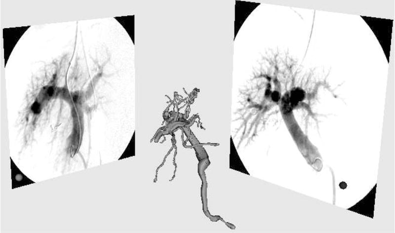
After calibration, the pose of the two image planes and the projection matrices on these planes are defined in the coordinate frame of the phantom. The calibration does not currently correct for radial distortions. Results from the calibration have shown that, without correction, the maximum reconstruction error from the calibration is around 2mm and is located on the periphery of the image. Figure 1 shows the 3-dimensional model of the vasculature before alignment and the two projection images.
Fig. 1.

System setup. 3-dimensional model of the vasculature is to be registered with two orthogonal fluoroscopic projections: anteroposterior (AP) on the right and lateral (LAT) on the left.
2.2 Registration
Our model-to-image metric is based on the work of Aylward et al. [7]. We seek the optimal pose of the 3-dimensional vascular model, extracted from the pre-operative MR or CT, given the two projection images, AP and LAT.
Given a centerline point X in the 3-dimensional model, we project that point onto the 2-dimensional image using the projection matrix previously computed from the calibration stage. The associated radius R at that point is also projected on the plane by projecting a vector parallel to the image plane at position X with a magnitude R.
After projection, a 2-dimensional centerline point x with associated radius r is defined. The metric is defined by the sum of the Gaussian-blurred intensity values in the 2D image at the projected model points. From the DSA images, one can notice that the vasculature has lower intensity values than the background, therefore the optimal alignment is obtained when the metric is minimal. For each point x, the amount of blurring is proportional to the radius r at that point.
Also, since larger vessels have greater contrast on the X-ray angiograms, we weight the metric value at each point proportionally to the radius so that larger vessels drive the optimization process more than smaller ones. Equation 1 describes our metric.
| (1) |
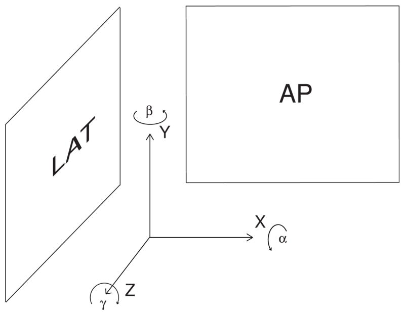
Next we align the registration frame such that the Z-axis axis is orthogonal to the AP plane and the X-axis axis is orthogonal the LAT plane as shown in figure 2. We assume from the clinical setup that the two fluoroscopic digitizers are orthogonal, however, since they may not be perfectly orthogonal, we optimize the orientation of this registration frame to maximize these alignments. This axis configuration defines a relationship between each parameter of the rigid body transform and the two views as described in table 1.
Fig. 2.

Reference frame used for registration.
Table 1.
Relationship between the parameters of the transformation (described in figure 2) and the two projected views.
| Parameter | α | β | γ | x | Y | z |
|---|---|---|---|---|---|---|
| View Plane | LAT | AP,LAT | AP | AP | AP,LAT | LAT |
Table 1 details that parameter optimization could be separated by view. However the genetic algorithm optimizer [12] we are using does not support separable parameters and multiple metric values. Therefore we have chosen to tune each parameter independently. Independent parameter optimization can be performed using two different strategies. First option consists of using each view separately and optimizing the parameters from that plane. For instance, from table 1, the AP view optimizes β,γ,x and y and the LAT view optimizes α,β,y and z. However, unreported experiments show that the presence of local minima in the metric precludes the registration from converging. The second optimization strategy consists of optimizing each parameter independently and use the appropriate view (or combination of views) to drive the registration. This optimization is used in our experiments. Figure 3 shows that our metric is smooth and free of local minima near its optimum. These graphs were generated using a vascular model of a human liver from a preoperative MR and the corresponding intraoperative DSA images.
Fig. 3.
Plots of the model-to-image metric.left: translation in X and Y. right: rotation in alpha and beta.
Next we report results using clinical data.
3 Results
For the following experiments a Siemens Neurostar biplane digital angiographic unit was used to obtain X-ray angiograms. The fields of view ranged from 8.7° to 16.5°. Images were captured and stored as 8-bit 884×884 pixel images. Pre-operative images of the 3D liver vasculature were acquired by MR on a Siemens MagicVision 1.5T system with collimation 0.86×0.86×3mm. Voxel size was variable, but around 1.0×1.0×3mm. We conducted multiple experiments to evaluate the speed, robustness and accuracy of our algorithm on five sets of images from five patients.
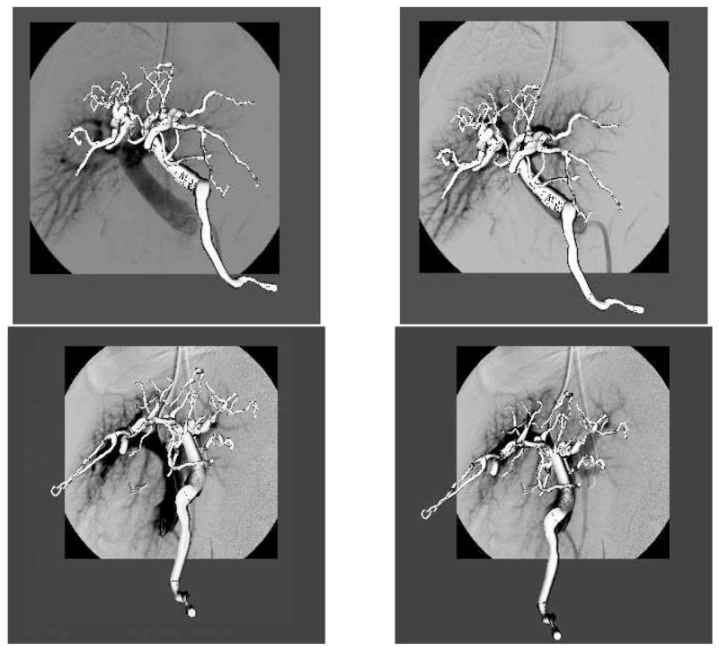
The first experiment verified the method’s ability to align the pre-operative model with the DSA images. In the operating room, calibration was performed before surgery as well as the extraction of the vascular trees from MR volumes. The pose of the 3D vascular model was initialized by aligning the center of mass of the vasculature with the origin of the reference frame (from the calibration phantom). This is a valid assumption since the vascular tree has to be centered on the DSA image to obtain good quality images. Second, the orientation of the model is initialized using prior knowledge about the position of the two image planes; by design, the AP view corresponds to the coronal plane and the LAT view to the sagittal plane of the MR. Given this initial pose, registration was conducted using a uniform subsampling of vascular models to 150 points for the metric. Our method converged for the five datasets in less than 20 seconds on a Pentium 4, 2.2GHz PC using 50 iterations, i.e each parameter was successively optimized 50 times. Figure 4 shows the qualitative validation of the registration.
Fig. 4.

Qualitative results of the 3D/2D registration. Vasculature before (left) and after registration (right) for both anteroposterior (top) and lateral (bottom) views
Next we conducted a Monte-Carlo validation experiment. For the five datasets, an initial registration was performed using Liu’s method [9], then 100 Monte-Carlo iterations were computed by adding random offsets (±20mm) and rotations (±10°). Table 2 summarizes the results of our experiment.
Table 2.
Final displacement from the Monte-Carlo experiment on five clinical datasets.
| Parameter | Mean (SD) |
|---|---|
| α | 0.60(1.91)° |
| β | 0.12(1.27)° |
| γ | 0.89(1.82)° |
| x | −0.27(1.19)mm |
| y | 0.61(0.91)mm |
| z | 0.18(0.90)mm |
Our registration converged 95% of the time. Registration failure occured when the registration was initialized far from the solution. This issue is discussed next.
4 Discussion and Conclusions
Even showing promising results, we are conscious that our method has some limitations.
The main limitation is the use of rigid body transformation. We assume that non-rigid deformations are negligible for three reasons. First, TIPS patients possess livers that are hard, dense, fibrotic and generally rigid. This means that although both needle pressure and respiration may displace the liver, neither is likely to deform it. Second, the portions of the hepatic and portal venous systems relevant to TIPS are located within this rigid liver. Third, the liver is bounded on three sides by the bony ribcage and superiorly by the diaphragm; it is additionally tethered by the left and right triangular ligaments and by the falciform ligament, all of which limit or preclude rotation.
The second limitation is the starting pose for the registration. From the clinical datasets we have found that 20mm and 10° were the maximal displacements. However, in some cases the registration fails and we are currently implementing a random sample consensus type algorithm which should improve our success rate.
In conclusion, we have developed a new model-to-image registration algorithm, which is driven by the image intensities of two fluoroscopic projections images. Our technique does not require the specification of correspondences between blood vessel from the 3-dimensional model and their 2-dimensional projections. Our method shows excellent results on real datasets. We are conscious that the validation part of this study does not address the clinical accuracy of the registration and we are currently extending the validation to include this aspect.
Our software was implemented using the Insight Toolkit [13].
Acknowledgments
This work is funded by NIH-HLB R01 HL69808.
References
- 1.Penney GP, Weese J, et al. A Comparison of Similarity Measures for Use in 2D-3D Medical Image Registration. IEEE Trans Med Imaging. 1998;17(4):586–595. doi: 10.1109/42.730403. [DOI] [PubMed] [Google Scholar]
- 2.McLaughlin RA, Hipwell JH, et al. A Comparison of a Similarity-Based and a Feature-Based 2-D-3-D Registration Method for Neurointerventional Use. IEEE Trans Med Imaging. 2005;12(8):1058–1066. doi: 10.1109/TMI.2005.852067. [DOI] [PubMed] [Google Scholar]
- 3.Nicolau S, Pennec X, Soler L, Ayache N. An Accuracy Certified Augmented Reality System for Therapy Guidance. Proc. of the 8th European Conference on Computer Vision (ECCV 04), Part III, volume LNCS 3023; 2004. pp. 79–91. [Google Scholar]
- 4.Jolly B, Van Horn M, Aylward S, Bullitt E. Needle tracking and detection in the TIPS endovascular procedure. MICCAI 2003. LNCS 2878:953–954. [Google Scholar]
- 5.Kerrien E, Berger M-O, et al. Fully automatic 3D/2D subtracted angiography registration. MICCAI 1999. LNCS 1679:664–671. [Google Scholar]
- 6.Albert CS, Chung Ho-Ming Chan, et al. 2D-3D Vascular Registration Between Digital Subtraction Angiographic (DSA) And Magnetic Resonance Angiographic (MRA) Images International Symposium on Biomedical Imaging. 2004:708–711. [Google Scholar]
- 7.Aylward S, Jomier J, et al. Registration of Vascular Images International Journal of Computer Vision. November 2003;:15. [Google Scholar]
- 8.Aylward S, Bullitt E. Initialization, Noise, Singularities, and Scale in Height-Ridge Traversal for Tubular Object Centerline Extraction. IEEE Transactions on Medical Imaging. Feb, 2002;:61–75. doi: 10.1109/42.993126. [DOI] [PubMed] [Google Scholar]
- 9.Liu A, Bullitt E, Pizer SM. 3D/2D registration using tubular anatomical structures as a basis. MICCAI’98, Lecture Notes in Computer Science. 1496:952–963. [Google Scholar]
- 10.Rosenthal M, Weeks S, et al. Intraoperative tracking of anatomical structures using fluoroscopy and a vascular balloon catheter. MICCAI 2001; Lecture Notes in Computer Science 2208. :1253–1254. [Google Scholar]
- 11.Venkatraman V, Van Horn M, Weeks S, Bullitt E. Liver Motion Due to Needle Pressure, Cardiac and Respiratory Motion During the TIPS Procedure. MICCAI 2004; Lecture Notes in Computer Science 3217. :66–72. [Google Scholar]
- 12.Styner M, Gerig G. Technical Report, BIWI-TR-179. Evaluation of 2D/3D bias correction with 1+1ES optimization. [Google Scholar]
- 13.The Insight Toolkit. National Library of Medicine Insight Segmentation and Registration Toolkit. http://www.itk.org.


