Abstract
The use of two different monoliths located in capillaries for on-line protein digestion, preconcentration of peptides and their separation has been demonstrated. The first monolith was used as support for covalent immobilization of pepsin. This monolith with well defined porous properties was prepared by in situ copolymerization of 2-vinyl-4,4-dimethylazlactone and ethylene dimethacrylate. The second, poly(lauryl methacrylate-co-ethylene dimethacrylate) monolith with a different porous structure served for the preconcentration of peptides from the digest and their separation in reversed-phase liquid chromatography mode. The top of the separation capillary was used as a preconcentrator, thus enabling the digestion of very dilute solutions of proteins in the bioreactor and increasing the sensitivity of the mass spectrometric detection of the peptides using a time of flight mass spectrometer with electrospray ionization. Myoglobin, albumin, and hemoglobin were digested to demonstrate feasibility of the concept of using the two monoliths in-line. Successive protein injections confirmed both the repeatability of the results and the ability to reuse the bioreactor for at least 20 digestions.
Keywords: nanoHPLC, Enzymatic reactor, Monolithic columns, Mass spectrometry, Pepsin, Immobilized enzyme
1. Introduction
Every protein features a unique sequence of amino acid residues. Deciphering the sequence is a key step in proteomics and different strategies can be applied to address this challenge. One of these strategies, the bottom-up approach, involves protein digestion to produce smaller peptide fragments, which are then separated and identified. In the most common implementation, each step is carried out separately and requires both time and manual handling. In order to avoid these drawbacks, systems are being developed that enable in-line protein digestion using an immobilized enzyme reactor followed by liquid chromatographic separation of the resulting peptides and their characterization using a coupled electrospray ionization (ESI) or matrix-assisted laser desorption ionization (MALDI) with mass spectrometry (MS) [1–6]. All steps following the protein sample preparation starting from injection to data interpretation should be automated. Consequently, this approach minimizes both the risk of mishandling sample and the time required to complete the analysis. The most common enzyme currently used for the digestion of proteins is trypsin. This enzyme exhibits good specificity and a large database of peptide fragments, characterizing a vast variety of proteins, has already been created. Given that the size of samples handled in proteomics is very small, it is desirable to develop miniature immobilized enzyme reactors placed in capillaries or microfluidic devices for such studies.
Proteolysis in solution is carried out with small amounts of enzyme to avoid the undesired autodigestion that yields fragments obscuring those originating from the proteins of interest. Therefore, long reaction times are required to completely digest the proteins. In contrast, immobilization enables the preparation of reactors characterized by a high local concentration of the enzyme and very fast reaction kinetics. The “site isolation” effect then prevents the immobilized enzymes to digest each other. Although proteolytic enzymes immobilized on porous particles have long been known [7] their use in proteomics is limited [8–12]. In contrast, monoliths are rapidly gaining popularity as carriers for the immobilization of trypsin [6,13] and other enzymes since the fast mass transport characteristic of monoliths further increases the reaction rate. Numerous reviews have appeared describing in detail the application of monolithic supports in systems that enable fast enzymatic conversion [14–15], their use for the fabrication of immobilized microfluidic enzymatic reactors [16,17], and more specifically for the immobilization of trypsin [18].
Monoliths were first used as stationary phases in high-performance liquid chromatography (HPLC) [19–22]. The monolithic structure fills the entire column volume and does not contain any interparticular voids typical of classical columns packed with particulate stationary phases. As a result, all of the mobile phase must flow through the monolith thus replacing the usual diffusional mass transport with much faster convection. The organic polymer monoliths are prepared from liquid precursors by polymerization in situ [20]. These and many other advantages of monoliths have led to their acceptance in chromatography and other fields. Their applications in a variety of applications including HPLC, gas chromatography, capillary electrochromatography (CEC), and solid-phase extraction has recently been summarized in several reviews [23–35] and books [36–37].
We advocated the use of porous polymer monolithic supports for immobilization of trypsin more than a decade ago [13]. Our initial research that were later extended to demonstrate applications of monoliths with various chemistries and in various sizes and formats [6, 13, 38–40] served as an inspiration to numerous immobilization studies in other laboratories [17]. In this study, we report immobilization of another proteolytic enzyme – pepsin, which digests proteins at acidic pH, a property that facilitates the direct coupling of the monolithic reactor with ESI-MS. Pepsin should not be seen as an alternative to trypsin for protein identification but rather as a complementary tool that may be used both to determine and confirm the respective order of each peptide fragment obtained from the tryptic digestion [41]. In order to achieve this, the cleavage sites favored by the two enzymes must be different, which is the case with trypsin and pepsin. Indeed, trypsin cleaves proteins specifically at the C-end of the Arg and Lys residues while pepsin at pH 2 cleaves mainly at C-end of Phe and Leu residues [42]. The specificity of pepsin is lower than that of trypsin and some amino acid sequences are not cleaved despite the presence of Phe and Leu, while other sequences can be cleaved even in their absence. Although this would be detrimental for protein identification, this lack of specificity can be utilized for quantitative protein analysis [43,44]. Due to miscleavages, pepsin digestion generates longer peptides that provide a signature of a specific protein. Thus, pepsin digestion has been successfully applied to quantitative protein analysis affording the reproducible formation of specific peptide markers [43]. Pepsin digestion is also a critical step in the hydrogen-deuterium exchange mass spectrometry for the analysis of protein dynamics [45].
In contrast to trypsin, immobilization of pepsin on solid supports is less common. For example, Krenkova et al. modified the inside wall of a 10 µm I.D. capillary with epoxy silane, then hydrolyzed the epoxide and oxidized the resulting diol with periodate to obtain aldehyde surface groups subsequently used to immobilize pepsin [46]. Following stabilization of the linkage with sodium cyanoborohydrate, this capillary was used in flow-through mode in a process involving the capillary zone electrophoresis separation of cytochrome c, myoglobin, and mellitin, followed by digestion of the separated proteins, and detection of the resulting peptides via on-line coupled ESI-MS. Similarly, Schoenherr et al. prepared 5 cm long poly(glycidyl methacrylate-co-ethylene dimethacrylate) monolith in 48 µm I.D. capillary [47] and modified it as described above to obtain adehyde moieties for the attachment of pepsin. The immobilized pepsin microreactor was then used in capillary electrophoresis-digestion- capillary electrophoresis configuration with ESI-MS detection to create two-dimensional peptide maps of cytochrome and myoglobin. These multistep column preparation processes had to be used because the direct reaction of enzyme with epoxide [7,46] could not be used as pepsin is known to denature in basic environment and therefore it must be immobilized from its solution in acid, typically at pH 4, conditions that would lead to hydrolysis of the reactive epoxide functionalities rather than coupling of the enzymethe.
Efficient identification of peptides resulting from protein digestion requires their separation to precede the MS detection. Although the digest can be collected off-line, desalted, preconcentrated and then injected in the LC-MS system, an in-line system including enzymatic reactor, preconcentrator, and HPLC column is more advantageous since it enables the combination of all of these steps without any manipulation and facilitates automation. In contrast to electrophoretic separation systems mentioned above, the combination of LC with ESI-MS is also easier to implement. Monolithic polymers can be used for all the three functions. This report describes an on-line system in which model proteins myoglobin, albumin and hemoglobin are digested by pepsin immobilized in a monolithic polymer-based microreactor, the resulting peptides being then concentrated and separated in a methacrylate-based monolithic column using HPLC followed by ESI-MS detection.
2. Materials and Methods
2.1. Chemicals
Ethylene dimethacrylate (EDMA), lauryl methacrylate (LaMA), 1-propanol, 1,4- butanediol, 2,2-azobisisobutyronitrile (AIBN), 3-(trimethoxysilyl)propyl methacrylate, tris(hydroxymethyl)aminomethane (Tris), urea (98%), iodoacetamide and 1,4-dithio-DL- threitol (>95%) were purchased from Aldrich (Milwaukee, WI, USA). Polymerization inhibitors were removed from EDMA and LaMA by passing them through a column filled with activated basic alumina (Aldrich) while EDMA was distilled under reduced pressure. 2-Vinyl-4,4-dimethylazlactone (VAL) was a generous gift from 3M company (St Paul, MN). Acetonitrile and water (both of MS purity grade), sodium hydroxide, hydrochloric acid, acetic acid, formic acid, bovine blood hemoglobin, ovalbumin from chicken egg white, and equine heart myoglobin were obtained from Sigma (St. Louis, MO, USA).
2.2. Instrumentation
Scanning electron micrographs of monoliths were obtained using a S-4300 SE/N scanning electron microscope (Hitachi, Pleasanton, CA, USA).
LC experiments were performed with a nanoAcquity UPLC system (Waters, Milford, MA, USA), equipped with pumps delivering the mobile phase at a flow rate 0.2-100 µL/min and an auto-sampler with a 2 µL sample loop. The mobile phase for the LC separations was 2% formic acid in water (A) and 2% formic acid in acetonitrile (B). The mobile phase gradient included 100% A for the initial 25 min followed by a linear increase to 80% B in 40 min and keeping this composition for another 25 min. After this sequence, the mobile phase was switched back to A and the system was equilibrated for 40 min prior to the next injection. The typical flow rate was 500 nL/min.
A time-of-flight mass spectrometer (Micromass LCT, Manchester, UK) was used for detection. Data were acquired between 600 and 1200 Thompson. A Picoview nanospray interface (New Objective, Woburn, MA, USA) was used for ESI, with a 3 cm × 10 µm I.D. distal coated silica tip (New Objective). The emitter tip was placed at a distance of ca. 5 mm from the MS entrance in an angle of approximately 45 °. In order to get a stable spray, the capillary voltage was adjusted in the range of 1600–1800 V.
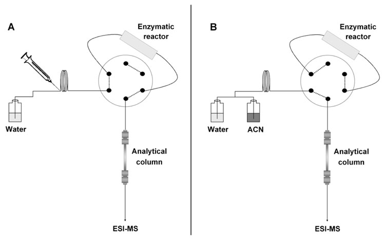
A 6-port analytical Cheminert valve equipped with an electric actuator (Vici Valco, Houston, TX, USA) was used to bypass the enzymatic reactor during the peptide separation to prevent pepsin from denaturing by acetonitrile (Figure 1). The valve allowed flow through the reactor for the initial 25 min, then automatically switched to bypass the reactor and finally switched back to the initial position 5 min before the next injection.
Figure 1.
Scheme of the in-line system: (A) protein solution is injected in the immobilized pepsin reactor in 2% aqueous formic acid, digested, and peptides are trapped on the top of HPLC column; (B) the reactor is bypassed and peptides are separated in a gradient of acetonitrile.
2.3. Preparation of protein solutions
To 100 µL of a solution containing 1 mg hemoglobin or albumin (both proteins contain cysteine residues) in 0.1 mol/L tris buffer pH 7.8 was added 5 µL of 200 mmol/L 1,4-dithio-DL-threitol solution prepared in 100 mmol/L tris buffer, after mixing, the solution was allowed to react for 1 h at room temperature. The sulfhydril functionalities in the reduced protein were alkylated with 20 µL of 200 mmol/L iodoacetamide solution in 100 mmol/L tris buffer for 1 h. Then, 20 µL of the 1,4-dithio-DL-threitol solution was added to neutralize any unreacted iodoacetamide and the mixture allowed to react at room temperature for another 1 h. Protein solutions were then diluted to a concentration of 1 µmol/L using 10 mmol/L aqueous HCl (pH=2). As myoglobin does not include cysteine residues, it was dissolved directly in 10 mmol/L aqueous HCl to achieve a concentration of 1 µmol/L. Protein solutions were kept at 15 °C in the sample rack, and were freshly prepared at least every 4 days. The typical injected volume of 2 µL contained 2 pmol of the protein.
2.4. Preparation of monolithic capillary column
Polyimide coated fused-silica capillaries of 100 µm I.D. were purchased from Polymicro Technologies (Phoenix, AZ, USA). Their inner surface was vinylized to enable covalent attachment of the monolith. The capillary was activated by sequential rinsing with acetone, water, 200 mmol/L NaOH, water, 200 mmol/L HCl, ethanol. Vinylization was achieved by pumping through the capillary 20 wt.% solution of 3-(trimethoxysilyl)propyl methacrylate in ethanol adjusted to pH 5 with acetic acid at a flow rate of 250 nL/min for 1 h using a syringe pump (KdScientific, New Hope, PA, USA). The capillary were then rinsed with acetone, dried in stream of nitrogen, and kept at room temperature.
The vinylized capillary was filled with a mixture containing 24% lauryl methacrylate, 16% ethylene dimethacrylate, 45% 1-propanol, 15% 1,4-butanediol (all weight percentages) and 1% AIBN (with respect to monomers). After sealing the ends of the capillary with a rubber septum, 20 cm long monolithic column was prepared by heating in a 70 °C water bath (VWR, Scientific Products, West Chester, PA, USA) for 24 h. After removing the seals, monolithic columns were washed with acetonitrile at a flow rate of 250 nL/min for 5–10 min using the liquid chromatographic pump system until the back pressure was stable. When not in use, the columns were stored in 1:1 water-acetonitrile mixture with both ends immersed in water.
2.5. Preparation of enzymatic microreactor
The vinylized I.D. 100 µm capillaries were filled with a mixture containing 24% vinylazlactone, 16% ethylene dimethacrylate, 34% 1-propanol, 26% 1,4-butanediol and 1% AIBN (with respect to monomers). Thermally initiated polymerization was carried out at 70 °C in a water bath for 24 h to afford the 15 cm long reactive monolithic support. The monolith was sequentially washed with acetone, 400 mmol/L buffer solution prepared from sodium citrate acidified to pH 5.0 by HCl at a flow rate of 1 µL/min for 20 min. Then a 5 mg/mL pepsin solution in the citrate buffer was pumped through the monolith at a flow rate of 250 nL/min for 3 h. The enzymatic reactor was stored filled with a solution of sodium citrate.
3. Results and Discussion
3.1. Monolithic support for enzymatic reactor
The preparation of the enzymatic reactors was carried out in two steps. The first step affords the monolithic support via the thermally initiated in situ polymerization of a mixture consisting of vinylazlactone, ethylene dimethacrylate, AIBN, and porogens. The second step, achieves the attachment of pepsin via its covalent immobilization onto the azlactone functionalities of the support.
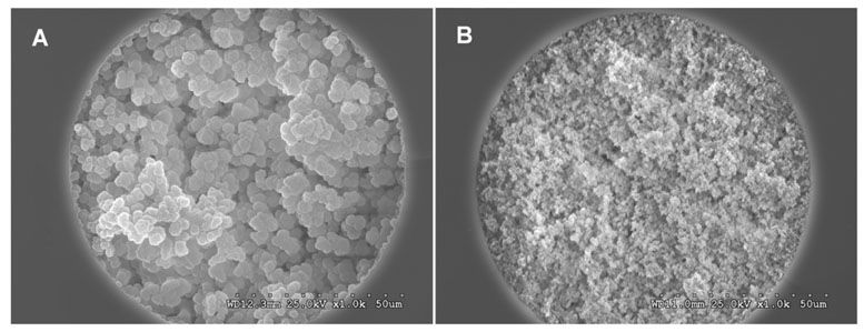
The porous properties of the monolithic support must be tuned to facilitate flow through the pores of the capillary column at a low back pressure. Therefore, we first varied the composition of the porogenic solvent in the polymerization mixture while keeping the contents of both monomers constant at 24% for vinylazlactone and 16% for ethylene dimethacrylate. A highly porous monolith, with the morphology shown in Figure 2A, was obtained by using a mixture consisting of 34% 1-propanol and 26% 1,4-butanediol as the porogens. This monolithic support contains enough active sites for immobilization of pepsin although its large microglobules only afford a relatively small surface area of less then 10 m2/g [39].
Figure 2.
SEM micrographs of the cross section of 100-µm I.D. monoliths in capillaries: (A) support for the enzymatic reactor prepared from 24% VAL, 16% EDMA, 34% 1-propanol, 26% 1,4-butanediol and 0.4% AIBN; (B) HPLC column prepared from 24% lauryl methacrylate, 16% ethylene dimethacrylate, 45% 1-propanol, 15% 1,4-butanediol and 0.4% AIBN; polymerizations were carried out at 70°C for 24 h.
The reactive amine functionalities of pepsin react readily with the azlactone groups in a ring opening reaction (Figure 3) that leads to the attachment of the enzyme to the monolithic support through a dipeptide spacer, which positively affects the activity of the biocatalyst. The pH value of the enzyme solution has to be carefully selected to preserve activity of the pepsin during this immobilization step while also preserving the ability of the azlactone moieties to react with the amine groups of pepsin. Typically, the reaction of azlactone functionalities is sluggish at low pH while pepsin is irreversibly denatured at pH values exceeding 6. Therefore, we carried out the immobilization reaction at a pH of 5.0 - a good compromise between the two opposing requirements. An additional benefit of this procedure is that the activity of the pepsin is reduced at this pH allowing for immobilization without the addition of an inhibitor to the pepsin solution in order to prevent autodigestion.
Figure 3.
Scheme of the immobilization reaction involving azlactone functionality of the monolithic poly(vinyl azlactone-co-ethylene dimethacrylate) support and pepsin.
3.2. Monolithic nanoHPLC column
The optimal pH value for protein digestion using pepsin is 2.0; such strong acidic conditions required for digestion are not well suited for separations involving typical silica-based packed reversed-phase columns since the C18 ligands tend to detach from the support at low pH. In contrast, most polymer-based chromatographic separation media can be used with mobile phases at any pH. For example, the ester groups of poly(glycidyl methacrylate-co-ethylene dimethacrylate) do not undergo hydrolysis even after treatment in concentrated HCl for several hours [48]. Therefore we used a methacrylate-based monolithic column for the separation of peptides in our in-line system. To obtain the desired retention, similar to that of typical reversed-phase columns, the monolithic column was prepared from a mixture including lauryl methacrylate with a C12 chain [49]. A column with a similar composition but prepared under different conditions was used for the CEC separation of peptides [50]. The porous structure of this monolith, shown in Figure 2B, differs significantly from that of the monolith used for the immobilization of pepsin: both its microglobules and its pores between their clusters are much smaller. As a result, this monolith exhibits a larger surface area. The combination of the larger surface area and more hydrophobic C12 chemistry enhances both retention and column efficiency. Obviously, the smaller pore size also leads to a decrease in permeability and higher pressure is required to achieve flow. For example, a back pressure of 1 MPa/cm is observed for water at a flow rate of 500 nL/min, which is 10 times higher than that found for the enzymatic reactor (0.1 MPa/cm). Despite this increase, the chromatographic system used in this study can easily handle the observed back pressures of up to 20 MPa without requiring any adjustment in the length of the separation column.
3.3. On-line digestion of proteins
Performance of the in-line protein digestion, preconcentration, and separation system was demonstrated using three proteins that differ widely in molecular sizes: myoglobin (MW 17 000), albumin (MW 42 700) and hemoglobin (MW 64 500). In the first implementation we started the in-line process with injection of the protein in the enzymatic reactor, followed by pumping the aqueous formic acid solution of digested peptides onto the top of the separation column where they were adsorbed. Then the mobile phase with a gradient of acetonitrile was pumped through both the reactor and the in line monolithic column to achieve separation of the peptides accumulated at the top of the hydrophobic monolith. While this in-line approach always worked well for the first run producing a set of well separated peptides, no digestion seemed to occur in subsequent runs. This was due to deactivation of the immobilized pepsin by acetonitrile. In contrast to trypsin [40], pepsin is rapidly denatured in this solvent. Therefore, a 6-port valve was inserted between the reactor and the separation column that enabled by-passing the enzymatic reactor during the separation cycle, thus avoiding contact of the enzyme and acetonitrile.
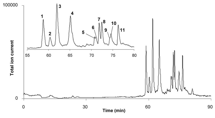
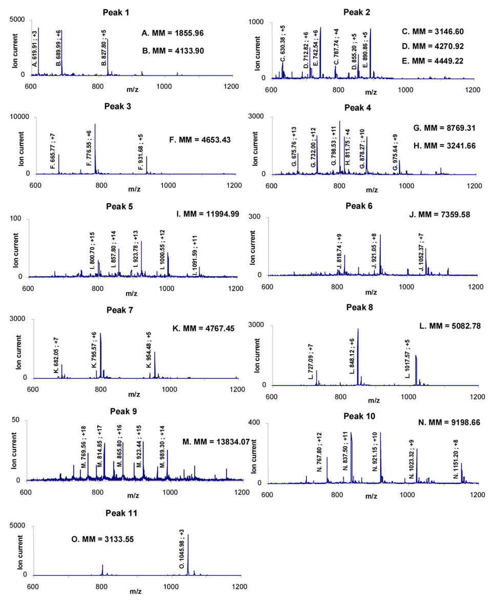
A typical chromatogram of peptides obtained after the digestion of a solution of 1 µmol/L myoglobin exhibits 11 distinct peaks (Figure 4) while mass spectra of the resulting peptides are shown in Figure 5. Mass to charge values and charges, found with the help of isotopic fragments, are also reported in Figure 5 and allow for the calculation of the molecular masses of the peptides. Fifteen peptides shown in Table 1 were identified with mass deviation of 2 Da or less and correspond to those found by others [43,51,52] in pepsin digests of horse heart myoglobin
Figure 4.
Separation of peptides resulting from the in-line digestion of 2 pmol of myoglobin in 15 cm × 100 µm I.D. immobilized pepsin reactor using a 20 cm × 100 µm I.D. monolithic column. Myoglobin concentration in solution 1 µmol/L, injection volume 2 µL; Mobile phase: 2% formic acid in water for 25 min pumped through the complete system followed by switch of the valve and use of a 0–80% linear gradient of acetonitrile gradient in 2% aqueous formic acid in 40 min. Flow rate of 500 nL/min.
Figure 5.
Mass spectra of 11 peaks obtained by on-line digestion/separation of myoglobin shown in Figure 4. Assignment of 15 peptide fragments associated with molecular masses are summarized in Table 1.
Table 1.
Assignment of peaks from Figure 4 to peptides in accordance to their molecular mass shown in Figure 5.
| Peak | Peptide | Mass | Position | Sequence |
|---|---|---|---|---|
| 1 | A | 1856.0 | 138 – 153 | FRNDIAAKYKELGFQG |
| B | 4133.9 | 70 – 106 | TALGGILKKKGHHEAELKPLAQSHATKHKIPIKYLEF | |
| 2 | C | 3146.6 | 106 – 135 | FISDAIIHVLHSKHPGDFGADAQGAMTKAL |
| D | 4270.9 | 33 – 69 | FTGHPETLEKFDKFKHLKTEAEMKASEDLKKHGTVVL | |
| E | 4449.2 | 70 – 109 | TALGGILKKKGHHEAELKPLAQSHATKHKIPIKYLEFISD | |
| 3 | F | 4653.4 | 30 – 69 | IRLFTGHPETLEKFDKFKHLKTEAEMKASEDLKKHGTVVL |
| 4 | G | 8769.3 | 30 – 106 | F + B |
| H | 3241.7 | 107 – 137 | ISDAIIHVLHSKHPGDFGADAQGAMTKALEL | |
| 5 | I | 11995.0 | 30 – 137 | F + B + H |
| 6 | J | 7359.6 | 70 – 137 | B + H |
| 7 | K | 4767.5 | 110 – 153 | AIIHVLHSKHPGDFGADAQGAMTKALELFRNDIAAKYKELGFQG |
| 8 | L | 5082.8 | 107 – 153 | H + A |
| 9 | M | 13834.1 | 30 – 153 | F + B + H + A |
| 10 | N | 9198.7 | 70 – 153 | B + H + A |
| 11 | O | 3133.6 | 1 – 29 | GLSDGEWQQVLNVWGKVEADIAGHGQEVL |
Analysis of the peptides indicates that cleavages occurred exclusively at Phe and Leu with one exception of an additional cleavage after Asp in fragment E. Although this cleavage site was previously reported for pepsin digest of myoglobin [51], it is also possible that it was caused by the formic acid present in the solution. It is worth noting that no cleavage occurred at several other Phe and Leu locations since the corresponding peptide fragments were not detected. This confirms that pepsin digestion is not exclusively specific for an amino acid residue and also depends on the neighboring sequence.
Myoglobin is a rather small protein and its digestion well studied. However, less is known about the digestion of larger proteins using pepsin. Therefore, we also used our enzymatic reactor for the digestion of albumin and hemoglobin. Figure 6 illustrates the in-line digestion of both of these proteins. Although interpretation of the results would be difficult due to the non-specific nature of this enzymatic cleavage, the chromatograms demonstrate that the immobilized pepsin reactor also enables the digestion of larger proteins that are more likely to be found in actual experimental samples.
Figure 6.
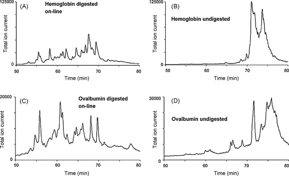
Separations resulting from the injection of 2 µL of 1 µmol/L hemoglobin (A) and albumin solution (C) in immobilized pepsin reactor and from the injection of these proteins in system in which the reactor is replaced with an empty capillary (B) and (D). Immobilized pepsin reactor 15 cm × 100 µm I.D., injection of 2 µL of 1 µmol/L protein solutions. For separation conditions see Figure 4.
3.4. Pre-concentration of peptides in the analytical column
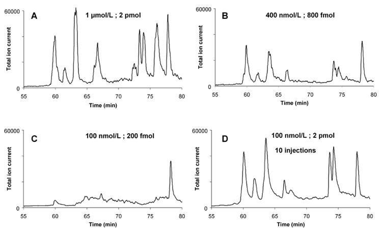
Typically, the sample quantities available in proteomics are small or their concentration is low. To determine the sensitivity of our system we injected 2 µL of myoglobin solution while varying its concentration between 0.1 and 1 µmol/L corresponding to 0.2–2 pmol of protein (Figure 7). The chromatograms suggest that 500 fmol of protein are sufficient to obtain the desirable MS results.
Figure 7.
Comparison of digestion/separation using myoglobin solutions with different concentration or different injected volume. Injection volume 2 µL; concentration 1 µmol/L (2 pmol injected) (A) , 400 nmol/L (800 fmol) (B), 100 nmol/L (200 fmol) (C); Ten successive injections of 2 µL of 100 nmol/L (2 pmol) myoglobin solution (D). For other conditions see Figure 4.
Since poor MS spectra were obtained after digestion of 100 nmol/L myoglobin solution, we used the hydrophobic separation column as a preconcentrator. The injections of 2 µL of the 100 nmol/L solution were repeated ten times with 5 min between each successive injection. As a result, the overall quantity of the digested protein is 2 pmol. The peptide peak intensities shown in Figure 7D are now again comparable to those obtained after a single injection of 1 µmol/L protein solution. This experiment illustrates that the monolithic analytical column can also be used as an efficient pre-concentrator and our in-line system can readily operate with very dilute samples. The peptides accumulate at the top of the separation column before their release and separation in the gradient of acetonitrile.
3.5. Stability of the enzymatic reactor
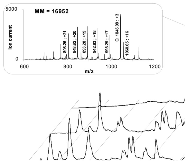
In order to test the stability of the system, a myoglobin solution was injected 30 times, the protein was digested and the peptides were separated. Figure 8 confirms that there is no significant change in elution profile during the first 20 injections with mass spectra identical to those presented in Figure 5. No intact myoglobin is detected in these runs. The performance of the system then slowly deteriorates and fewer peptides are detected as illustrated in the trace corresponding to the 25th injection shown in Figure 8. A large peak is detected at 76.5 min and its mass spectrum corresponds to intact myoglobin co-eluting with peptide O. These changes in activity may reflect the degradation of the enzyme or more likely, contamination of the aqueous part of the mobile phase pumped through the reactor with acetonitrile. The latter may result from the programming both independent pumps in the Waters LC system. A pressure spike occurring during sample injection and valve switching may allow a very small amount of acetonitrile to run through the enzymatic reactor.
Figure 8.
Repeated digestions of myoglobin in the enzymatic reactor. Inset: Mass spectrum of the peak eluting at 76.5 min after the 25th injection. For conditions see Figure 4.
Several reactors containing immobilized pepsin were prepared during this study using identical conditions. All tested reactors afforded similar results and could be used for at least 20 injections. In contrast, the monolithic separation capillary column did not need to be replaced at all despite its long term use at pH 2.0. As expected, the porous polymer monolith exhibits an excellent stability even under the harsh conditions used in these experiments.
4. Conclusion
Monolithic polymers are very useful building blocks for the creation of complex systems combining several functions/devices. They are becoming very popular as supports for immobilized enzymes and the fabrication of fast bioreactors. Simultaneously, they also enable rapid separations of peptides originating from the digestion step. The on-line configuration including monolithic bioreactor, preconcentrator, and separation HPLC column coupled with ESI-MS affords rapid in-line digestion of proteins, separation of peptides and characterization of their molar masses. Although the in-line concept with monolithic building blocks is demonstrated with pepsin, it can easily be extended to a variety of enzymes. Experiments with other proteolytic and glycolytic enzymes are currently in progress.
Acknowledgement
Support by grants of the National Institute of General Medical Sciences, National Institutes of Health (GM44885) and Pfizer Inc. is gratefully acknowledged. Characterization work at the Molecular Foundry was supported by the Director, Office of Science, Office of Basic Energy Sciences, Division of Materials Sciences and Engineering, of the US Department of Energy under contract No. DE-AC02-05CH11231. Insightful discussions with Violaine Augustin and Timothy Stachowiak are gratefully acknowledged.
Footnotes
Publisher's Disclaimer: This is a PDF file of an unedited manuscript that has been accepted for publication. As a service to our customers we are providing this early version of the manuscript. The manuscript will undergo copyediting, typesetting, and review of the resulting proof before it is published in its final citable form. Please note that during the production process errors may be discovered which could affect the content, and all legal disclaimers that apply to the journal pertain.
References
- 1.Girelli AM, Mattei E. J. Chromatogr. B. 2005;819:3. doi: 10.1016/j.jchromb.2005.01.031. [DOI] [PubMed] [Google Scholar]
- 2.Kallenberg AI, van Rantwijk F, Sheldon RA. Adv. Synth. Catal. 2005;347:905. [Google Scholar]
- 3.Massolini G, Calleri E. J. Sep. Sci. 2005;28:7. doi: 10.1002/jssc.200401941. [DOI] [PubMed] [Google Scholar]
- 4.Giordano RC, Ribeiro MPA, Giordano RLC. Biotechnol. Adv. 2006;24:27. doi: 10.1016/j.biotechadv.2005.05.003. [DOI] [PubMed] [Google Scholar]
- 5.Miyazaki M, Maeda H. Trends Biotechnol. 2006;24:463. doi: 10.1016/j.tibtech.2006.08.002. [DOI] [PubMed] [Google Scholar]
- 6.Peterson DS, Rohr T, Svec F, Fréchet JMJ. J. Proteome Res. 2002;1:563. doi: 10.1021/pr0255452. [DOI] [PubMed] [Google Scholar]
- 7.Turkova J, Blaha K, Malanikova M, Vancurova J, Svec F, Kalal J. Biochim. Biophys. Acta. 1978;524:162. doi: 10.1016/0005-2744(78)90114-6. [DOI] [PubMed] [Google Scholar]
- 8.Takeuchi S, Oike M, Kowitz C, Shimasaki C, Hasegawa K, Kitano H. Makromol. Chem. 1993;194:551. [Google Scholar]
- 9.Malmsten M, Xing KZ, Ljunglof A. J. Colloid Interface Sci. 1999;220:436. doi: 10.1006/jcis.1999.6540. [DOI] [PubMed] [Google Scholar]
- 10.Malmsten M, Larsson A. Colloids Surf., B Biointerfaces. 2000;18:277. doi: 10.1016/s0927-7765(99)00153-8. [DOI] [PubMed] [Google Scholar]
- 11.Wang R, Zhang Y, Ma G, Su Z. Colloids Surf., B Biointerfaces. 2006;51:93. doi: 10.1016/j.colsurfb.2006.05.015. [DOI] [PubMed] [Google Scholar]
- 12.Bilkova Z, Slovakova M, Minc N, Futterer CS, Cecal R, Horak D, Benes M, le Potier I, Krenkova J, Przybylski M, Viovy JL. Electrophoresis. 2006;27:1811. doi: 10.1002/elps.200500587. [DOI] [PubMed] [Google Scholar]
- 13.Petro M, Svec F, Fréchet JMJ. Biotech. Bioeng. 1996;49:355. doi: 10.1002/(SICI)1097-0290(19960220)49:4<355::AID-BIT1>3.0.CO;2-O. [DOI] [PubMed] [Google Scholar]
- 14.Josic D, Buchacher A. J. Biochem. Bioph. Methods. 2001;49:153. doi: 10.1016/s0165-022x(01)00195-6. [DOI] [PubMed] [Google Scholar]
- 15.Svec F, Fréchet JMJ. Science. 1996;273:205. doi: 10.1126/science.273.5272.205. [DOI] [PubMed] [Google Scholar]
- 16.Krenkova J, Foret F. Electrophoresis. 2004;25:3550. doi: 10.1002/elps.200406096. [DOI] [PubMed] [Google Scholar]
- 17.Svec F. Electrophoresis. 2006;27:947. doi: 10.1002/elps.200500661. [DOI] [PubMed] [Google Scholar]
- 18.Massolini G, Calleri E. J. Sep. Sci. 2005;28:7. doi: 10.1002/jssc.200401941. [DOI] [PubMed] [Google Scholar]
- 19.Hjertén S, Liao JL, Zhang R. J. Chromatogr. 1989;473:273. [Google Scholar]
- 20.Svec F, Fréchet JMJ. Anal. Chem. 1992;64:820–882. doi: 10.1021/ac00035a008. [DOI] [PubMed] [Google Scholar]
- 21.Tennikova TB, Svec F, Belenkii BG. J. Liq. Chromatogr. 1990;13:63. [Google Scholar]
- 22.Minakuchi H, Nakanishi K, Soga N, Ishizuka N, Tanaka N. Anal. Chem. 1996;68:3498. doi: 10.1021/ac960281m. [DOI] [PubMed] [Google Scholar]
- 23.Tanaka N, Kobayashi H, Nakanishi K, Minakuchi H, Ishizuka N. Anal. Chem. 2001;73:420A. doi: 10.1021/ac012495w. [DOI] [PubMed] [Google Scholar]
- 24.Legido-Quigley C, Marlin ND, Melin V, Manz A, Smith NW. Electrophoresis. 2003;24:917. doi: 10.1002/elps.200390136. [DOI] [PubMed] [Google Scholar]
- 25.Fu H, Huang X, Jin W, Zou H. Curr. Opin. Biotechnol. 2003;14:96. doi: 10.1016/s0958-1669(02)00006-x. [DOI] [PubMed] [Google Scholar]
- 26.Bedair M, El Rassi Z. Electrophoresis. 2004;25:4110. doi: 10.1002/elps.200406136. [DOI] [PubMed] [Google Scholar]
- 27.Cabrera K. J. Sep. Sci. 2004;27:843. doi: 10.1002/jssc.200401827. [DOI] [PubMed] [Google Scholar]
- 28.Jungbauer A, Hahn R. J.Sep.Sci. 2004;27:767. doi: 10.1002/jssc.200401812. [DOI] [PubMed] [Google Scholar]
- 29.Xie C, Fu H, Hu J, Zou H. Electrophoresis. 2004;25:4095. doi: 10.1002/elps.200406155. [DOI] [PubMed] [Google Scholar]
- 30.Svec F. J. Sep. Sci. 2004;27:1419. doi: 10.1002/jssc.200401825. [DOI] [PubMed] [Google Scholar]
- 31.Mistry K, Grinberg N. J. Liq. Chromatogr. 2005;28:1055. [Google Scholar]
- 32.Vegvari A. J. Chromatogr. A. 2005;1079:50. doi: 10.1016/j.chroma.2005.03.122. [DOI] [PubMed] [Google Scholar]
- 33.Svec F. J. Sep. Sci. 2005;28:729. doi: 10.1002/jssc.200400086. [DOI] [PubMed] [Google Scholar]
- 34.Svec F, Huber CG. Anal. Chem. 2006;78:2100. doi: 10.1021/ac069383v. [DOI] [PubMed] [Google Scholar]
- 35.Svec F. J. Chromatogr. B. 2006;841:52. doi: 10.1016/j.jchromb.2006.03.055. [DOI] [PubMed] [Google Scholar]
- 36.Deyl Z, Svec F. Capillary Electrochromatography. Vol. 62. Amsterdam: Elsevier; 2001. Journal of Chromatography Library. [Google Scholar]
- 37.Svec F, Tennikova TB, Deyl Z, editors. Monolithic Materials: Preparation, Properties, and Applications. Vol. 67. Amsterdam: Elsevier; 2003. Journal of Chromatography Library. [Google Scholar]
- 38.Xie S, Svec F, Fréchet JMJ. Biotech. Bioeng. 1999;62:30. doi: 10.1002/(sici)1097-0290(19990105)62:1<30::aid-bit4>3.0.co;2-e. [DOI] [PubMed] [Google Scholar]
- 39.Peterson DS, Rohr T, Svec F, Fréchet JMJ. Anal. Chem. 2002;74:4081. doi: 10.1021/ac020180q. [DOI] [PubMed] [Google Scholar]
- 40.Peterson DS, Rohr T, Svec F, Fréchet JMJ. Anal. Chem. 2003;75:5328. doi: 10.1021/ac034108j. [DOI] [PubMed] [Google Scholar]
- 41.Whitford D. Proteins: Structure and Function, Wiley, Chichester. 2005 [Google Scholar]
- 42.Keil B. Specificity of Proteolysis. Berlin: Springer-Verlag; 1992. [Google Scholar]
- 43.Bruyneel B, Hoos JS, Smoluch MT, Lingeman H, Niessen WMA, Irth H. Anal.Chem. 2007;79:1591. doi: 10.1021/ac0616761. [DOI] [PubMed] [Google Scholar]
- 44.Julka S, Regnier F. J.Proteome Res. 2004;3:350. doi: 10.1021/pr0340734. [DOI] [PubMed] [Google Scholar]
- 45.Wales TE, Enge JR. Mass Spectrom. Rev. 2006;25:158. doi: 10.1002/mas.20064. [DOI] [PubMed] [Google Scholar]
- 46.Krenkova J, Kleparnik K, Foret F. J. Chromatogr. A. 2007;1159:110. doi: 10.1016/j.chroma.2007.02.095. [DOI] [PubMed] [Google Scholar]
- 47.Schoenherr RM, Ye M, Vannatta M, Dovichi NJ. Anal. Chem. 2007;79:2230. doi: 10.1021/ac061638h. [DOI] [PMC free article] [PubMed] [Google Scholar]
- 48.Kalalova E, Radova Z, Svec F, Kalal J. Europ. Polym. J. 1977;13:287. [Google Scholar]
- 49.Eeltink S, Geiser L, Svec F, Fréchet JMJ. J. Sep. Sci. 2007;30:2814. doi: 10.1002/jssc.200700185. [DOI] [PMC free article] [PubMed] [Google Scholar]
- 50.Wu R, Zou HF, Ye ML, Lei ZD, Ni JY. Anal. Chem. 2001;73:4918. doi: 10.1021/ac010413y. [DOI] [PubMed] [Google Scholar]
- 51.Nelson RW. Mass Spectrom. Rev. 1997;16:353. doi: 10.1002/(SICI)1098-2787(1997)16:6<353::AID-MAS3>3.0.CO;2-G. [DOI] [PubMed] [Google Scholar]
- 52.Schwarzinger S, Ahrer W, Müller N. Monatsh. Chem. 2000;131:409. [Google Scholar]


