Abstract
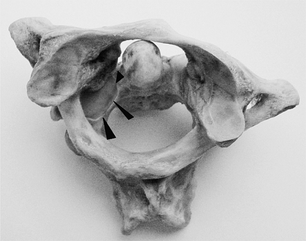
Posterior transarticular screw fixation C1-2 with the Magerl technique is a challenging procedure for stabilization of atlantoaxial instabilities. Although its high primary stability favoured it to sublaminar wire-based techniques, the close merging of the vertebral artery (VA) and its violation during screw passage inside the axis emphasizes its potential risk. Also, posterior approach to the upper cervical spine produces extensive, as well as traumatic soft-tissue stripping. In comparison, anterior transarticular screw fixation C1-2 is an atraumatic technique, but has been neglected in the literature, even though promising results are published and lectured to date. In 2004, anterior screw fixation C1-2 was introduced in our department for the treatment of atlantoaxial instabilities. As it showed convincing results, its general anatomic feasibility was worked up. The distance between mid-sagittal line of C2 and medial border of the VA groove resembles the most important anatomic landmark in anterior transarticular screw fixation C1-2. Therefore, CT based measurements on 42 healthy specimens without pathology of the cervical spine were performed. Our data are compiled in an extended collection of anatomic landmarks relevant for anterior transarticular screw fixation C1-2. Based on anatomic findings, the technique and its feasibility in daily clinical work is depicted and discussed on our preliminary results in seven patients.
Keywords: C1–C2, Atlantoaxial instability, Anatomy, Upper cervical spine, Cervical fusion
Introduction
Since Magerl has introduced posterior transarticular screw (PTS) fixation C1-2 to stabilize atlantoaxial instabilities, this procedure, with or without posterior laminar wiring and bone grafting, gained wide acceptance. It showed high fusion rates up to 100% [4, 12, 16, 18, 21, 49]. Biomechanically, it is superior to previous wire-based techniques and comparable to posterior lateral mass C1/Isthmus C2 (or ‘pedicle’ C1/Isthmus C2) fixations (LM/ISF) [14, 15, 18, 19, 29, 38, 47]. Referring to the close merging neighbourhood of neurovascular structures C1-2, the anatomic feasibility of PTS raised concerns: Complications such as misplacement of the screws with dural tears, injury to the vertebral arteries in about 2–5% [12, 49, 54], injury to the hypoglossus nerve or even the spinal cord, screw breakages, screw misplacements in up to 15% [16], and revision surgeries in up to 17% [2, 5, 10, 16, 34, 49, 53, 54] demanded further research on the anatomic limits of PTS. Hence, almost 20% of axis vertebra are not suitable for bilateral PTS due to thin diameter of the pars interarticularis C2 and neurocentral junction of C2, respectively [35, 39].
On the other hand, LM/ISF prevents articular damage, enables anatomic reduction under visible control of the atlantoaxial joints, whereas its technical approach in a narrow field of instrumentation is demanding [13, 20, 44]. Although many authors recommended techniques for safe screw trajectories with PTS [8, 9, 16, 17, 23, 34, 44, 55], nowadays computer assisted surgery (CAS) and intraoperative CT-imaging [11] is supposed to increase the accuracy of screw placement C1-2. But, PTS with CAS shows its own shortcomings, e.g. in highly unstable traumatic injuries of the atlas only C2 can be referenced [21, 41, 44, 45, 46, 53]. A less discussed problem of PTS concerns its operation time and ‘crop damage’ to surrounding soft-tissues due to stripping of posterior neck muscles, particularly in elderly patients [37, 43]. This disadvantage can only be reduced using semi-percutaneous instrumentations, which show their own restrictions [4, 36].
Anterior transarticular screw (ATS) fixation C1-2 has been first described by Barbour [3] in 1971. Nevertheless, this technique seems to be neglected in the literature unless its value has not been evaluated sufficiently [42, 52].
In face of above-mentioned shortcomings of PTS and LM/ISF, we questioned the value of anterior retropharyngeal fusion C1-2 using a transcorporal–transarticular screw pathway and implemented it in seven cases with atlantoaxial instability. As with PTS and LM/ISF, the technique showed a shallow learning curve.
Hence, to work up the anatomic feasibility of ATS, we reviewed the literature concerning morphometric parameters C1-2. The reviewed articles showed only one paper addressing measurements on cadavers from European origin and the distance between the mid-sagittal-line C2 to medial border of the vertebral artery groove (VAG) [26]. This distance is of paramount importance in ATS. Therefore, we conducted CT based morphometric measurements of axis and atlas vertebra in 42 healthy patients, respectively. This approach will give a better cross-section for daily practice. This paper illustrates the anatomical feasibility and our experience with ATS in view of a selected review of the literature.
Methods
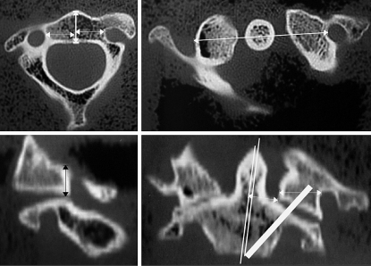
The CT scans of 42 patients without cervical pathology were taken for as basis of our measurements. There were 26 males and 16 females, average age was 39.8 years (5–67) in males, 48.5 years (9–89) in females, and at all 43.1 years (5–89). No patient suffered from osteoporosis, metastatic or other bone diseases. Three-dimensional CT reconstructions (General Electric, Light Speed Plus) with fine CT scans (2 mm slice thickness, 1.5 mm slice spacing, 0.75 pitch) and morphometric measurements were done by one of the authors (D.U.). For the measurements, the most medial border of the VAG was identified inside the vertebral body of C2 (VB-C2) in axial CT scans for both sides. Next, the mid-sagittal line of the axis was drawn. Perpendicular to this line the distance between mid-sagittal-line C2 and medial border of VAG was measured for both sides (Fig. 1). The average vertebral body depth at the site of aforementioned measurements was 14.72±2.22 mm (9–19) resembling the various locations of the most medial border of vertebral artery (VA) inside C2 in frontal plane.
Fig. 1.
In preoperative atlantoaxial CT scans, relevant distances for ATS are measured. Upper left Vertebral body depth and distance between VAG and mid-sagittal-line C2. Upper right Distance between transverse foramen C1 and mid-sagittal-line C1-2. Lower left Medial height of lateral mass C1. Lower right Width between mid-sagittal-line C2 and medial offset of superior facet C2 including the ‘real’ pedicle C2, possible screw inclination and width of lateral mass C1
To make clear, the technique of ATS and the sophisticated anatomy of the atlantoaxial complex, atlas and axis cadaver vertebra were worked up graphically. In summary, CT scans were performed and three-dimensional reformations calculated by two of the authors (B.B., S.K.). Using a prototyping program (Catia V5 R12, Dassaul Systems, France), the IGES files were converted, worked up for volume model and meshed. The product was merged with a free model of a reconstructed standard 3.5 mm screw as used in odontoid screw fixation and ATS. Particularly, the sectioned graphics will help to understand and navigate inside C1-2 in respect to the VA. They depict the feasibility of ATS.
Results
The data of our measurements are summarized in Table 1. Our results and morphometric thresholds for navigation inside C1-2 are depicted through Figs. 2, 3, 4, 5, 6 and 7. Patients’ characteristics are summarized in Table 2 and clinical cases presented in Figs. 8 and 9.
Table 1.
Morphometric measurements (mm) C2
| dMVAG | Mean | SD | Min | Max |
|---|---|---|---|---|
| Left | 14.0 | 1.95 | 10 | 18 |
| Right | 14.2 | 2.0 | 9 | 18 |
| Left, females | 13.3 | 1.95 | 11 | 17 |
| Right, females | 14.1 | 1.84 | 10 | 16 |
| Left, males | 14.4 | 1.86 | 11 | 18 |
| Right, males | 14.4 | 2.14 | 9 | 18 |
| Workspace C2 males | 28.7 | 3.56 | 22 | 35 |
| Workspace C2 females | 27.4 | 3.12 | 21 | 32 |
dMVAG distance between mid-sagittal-line C2 and medial border of vertebral artery groove
Fig. 2.
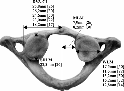
Morphometric parameters for screw placement inside C1. DVA-C1 distance vertebral artery groove C1 to mid-sagittal-line C1, SDLM sagittal depth of lateral mass C1, WLM width of lateral mass C1, MLM distance between mid-sagittal-line C1 and lateral mass C1
Fig. 3.
Morphometric parameters concerning course of the VA and screw placement inside C1-2. VAG distance between mid-sagittal-line C2 and vertebral artery groove C2—own results, EVA distance between entry point of vertebral artery to mid-sagittal-line C2, SFFA superior frontal facet angle C2, SFA superior facet angle C1 and C2, iFBW inferior frontal body width, PW width between mid-sagittal-line C2 and medial offset of superior facet C2 including the ‘real’ pedicle C2, IHLM internal height of lateral mass, m/f data separated for male and female specimen
Fig. 4.
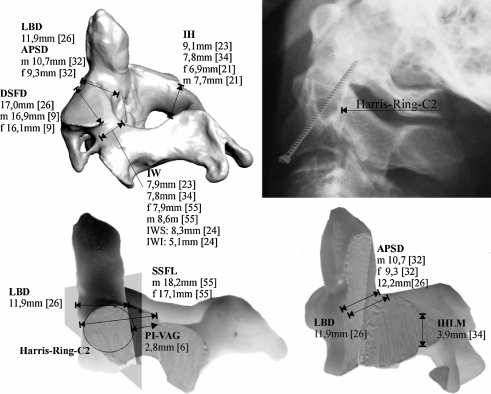
Morphometric parameters concerning screw placement in ATS and PTS. Upper right The Harris-Ring-C2 and its upper posterior bow resembles the posterior threshold to be passed by a screw in ATS. LBD lateral body depth; APSD anterior–posterior sagittal diameter of axis body; DSFD diagonal surface diameter of lateral mass; IH height of Isthmus C2; IW width of Isthmus C2; PI-VAG distance from pars interarticularis to posterior border of VAG; IHLM internal height of lateral mass C2; SSFL superior sagittal facet lenght; m/f data separated for male and female specimen
Fig. 5.
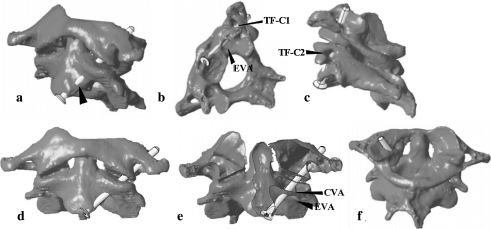
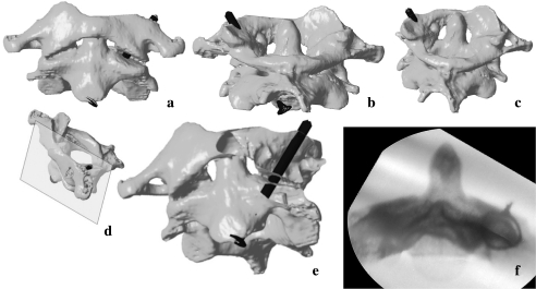
Pitfalls in ATS. a–d Too far lateral screw placement endangers the VA and increases risk of screw cut-out. b, e The osseous canal of the VA inside the lateral mass C2 can be harmed, if screw angulation is too steep. f A too far medialized screw can cause breaching of the atlantooccipital joint. TF-C1 transverse foramen C1, TF-C2 transverse foramen C2, CVA osseous canal of vertebral artery, EVA entry point of vertebral artery
Fig. 6.
Ideal screw placement in ATS (oversized screw lengths shown). a, b Screw entry point is to be chosen at the pinafore C2 for the first and a bit posteriorly underneath the pinafore C2 for the second screw to prevent screw cut-out anteriorly. c The screws should direct to the lateral rim of the lateral mass C1. d Image depicts plane of view in (e). e Ideal screw placement inside C1-2. f A cerclage wire surrounding the Isthmus C2 with the X-ray beam in direction to its angulation: the medial cortical border of Isthmus C2 resembles a possible lateral threshold for screw angulation
Fig. 7.
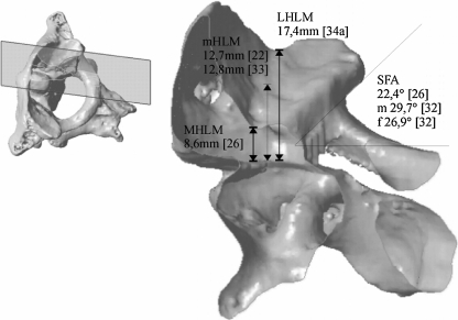
Morphometric parameters concerning screw placement inside the lateral mass C1. It resembles a cupped fossa and its medial height strongly differs from its lateral counterpart. Therefore, the length of screw taps should respect preoperative measurements. mHLM middle height of lateral mass C1, MHLM medial height of lateral mass C1, LHLM lateral height of lateral mass C1, SFA superior facet angle C1
Table 2.
Preliminary results and summary of characteristics in seven patients undergoing ATS
| Case no. | Age (years), sex | Diagnosis | Notes | Screw length (mm) | Complications | Follow-up (months) | Preliminary outcome |
|---|---|---|---|---|---|---|---|
| 1 | 35, m | Jefferson-4-part-#, burst # C5 | Tetraplegia sub-C5, ant. corpectomy w/fusion C4-6 using single approach | 40 | Subluxation at C6/7 w/o consequences | 15 | Stable ATS fixation; mobilized, but chairbound, C1-fracture united |
| 2 | 82, m | Kidney cell carcinoma with instability C1-2 and collapse of right lateral mass | Curettage of osteolysis C2 and supplementation of defect with PMMA | 40 | None | 3 | Patient died 3 months postoperative due to systemic progress of tumor disease |
| 3 | 68, f | Odontoid # type II w/fused atlantodental joint | Additionally odontoid screw fixation: ‘tripple fixation’ | 38 | Odontoid instability due to screw cut-out → posterior fusion C1-2 using ‘neon’-clamps | 6 | Pain-free, stable ATS fixation, C2-fracture united, posterior fusion C1-2 |
| 4 | 93, f | Odontoid # type IIa w/fused atlantodental joint | Fall out of bed, no change of ATS in control CT | 38 | None | 6 | Pain-free, stable ATS fixation; ROM cervical spine flex/ext: 30°–0°–50°; rot.: 30°–0°–30°, C2-fracture united |
| 5 | 80, f | Odontoid # type II w/fused atlantodental joint | – | 38 | None | 4 | Pain-free, stable ATS fixation, C2-fracture united |
| 6 | 26, m | Jefferson-3-part-# w/torn transverse atlantal ligament | Referred pain C2 left, preoperative HALO-traction 24 h | 36 | None | 3 | Pain-free, stable ATS fixation, implant removal scheduled, progressed union C1 |
| 7 | 84 ,f | Nonunion of odontoid fracture type II with screw cut-out after odontoid screw fixation | Implant removal and revision surgery using simultaneous approach | 36 | None | 1 | Pain-free, stable ATS fixation |
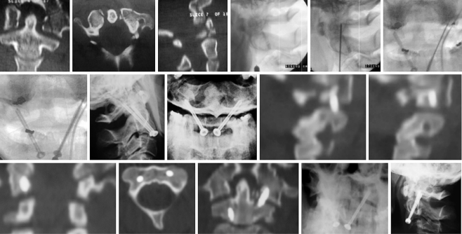
Fig. 8.
Case 1: unstable Jefferson’s fracture. After control of rotation C1-2, first and second k-wire placement underneath the pinafore C2, screw placement was performed. Postoperative CT scans showed favourable alignment C1-2 with solid screw purchase. One year after ATS, there was a fracture union and still solid screw purchase with stable atlantoaxial joints
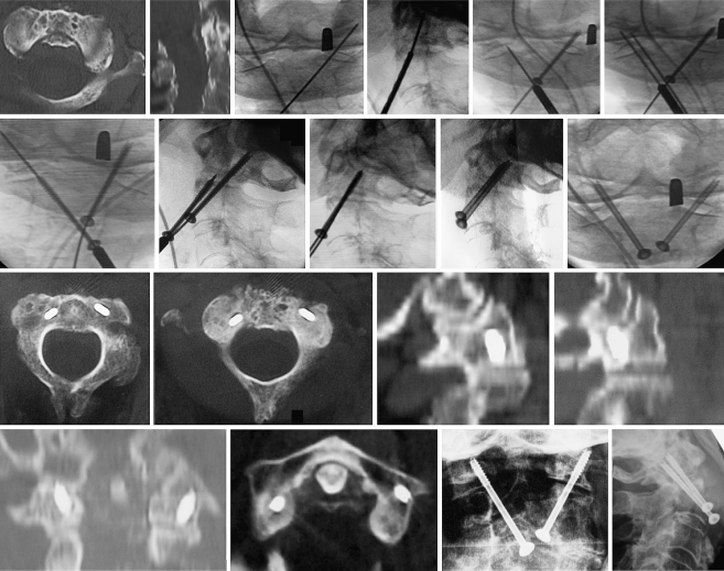
Fig. 9.
Case 4: unstable odontoid fracture with partially ankylosed atlantodental joint. Stiff neck did not enable k-wire and screw placement underneath pinafore C2. First k-wire placement is on the right too far medial. Correct k-wire placement is on the left. As there was correct rotation C1-2, the third k-wire was passed parallel to the first right-sided one. It guided to the lateral rim of the right lateral mass C1. Finally, solid screw purchase inside C1-2 was achieved. Operation time was 42 min. As suggested in final X-rays, there was some breaching of the right atlantooccipital joint without any clinical consequences. After 5 months, follow-up demonstrated solid screw anchorage, stable atlantoaxial joints, and a pain-free clinical result
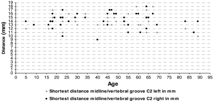
The distance between the mid-sagittal-line C2 and left medial border of the VAG was measured with 14.0±1.95 mm (10–18) and between the mid-sagittal-line C2 and right medial border of the VAG was measured with 14.2±2.0 mm (9–18) on average. At all, this distance measured 14.1±1.95 mm (9–18) in average. In females, this distance measured 13.3±1.95 mm (11–17) and 14.1±1.84 mm (10–16), respectively. In males, this distance measured 14.4±1.86 mm (11–18) and 14.4±2.14 mm (9–18), respectively.
As supposed, average and maximum distances measured in males were greater when compared to females. The depth of the body C2 at the level of aforementioned measurements was 14.72±2.22 mm (9–19) on average.
From these data, the calculated workspace C2 in frontal plane between both vertebral arteries is 28.7±3.56 mm (22–25) in males and 27.4±3.12 mm (21–32) in females. Interestingly, there was no trend towards a decreased distance between the mid-sagittal-line C2 and medial border of VAG in elderly patients (see Graph 1).
Graph 1.
Template showing age-related distances between mid-sagittal-line C2 and medial border of VAG in 42 patients. There was no trend towards decreased distances in young or elderly patients
In view of other morphometric studies (Figs. 2, 3, 4, 7) our data confirm, that in average there is at least 14 mm space in coronal plane inside C2 to place and angulate a 3.5 mm lag screw between the mid-sagittal-plane C2 and the medial border of the VAG.
Discussion
Brief history and techniques of ATS C1-2
ATS using the anterior retropharyngeal approach has been reported to be an effective alternate for stabilization of the atlantoaxial joint avoiding posterior approach and its inherent crop damage. In 1971, Barbour [3] described a technique in which transarticular screws were used to stabilize the lateral atlantoaxial joints in patients with odontoid fractures. Du Toit used this technique in an odontoid fracture and presented modifications with favourable outcome [7, 48]. In 1987, Leson et al. [31] described a modified technique in which the entry point for the screws was given lateral the mid-sagittal line at the small groove of the lateral mass beneath the facets. The technique has successfully been performed in seven patients with usual indications, such as nowadays for PTS. Apostolides et al. extended these aforementioned techniques to a triple anterior screw fixation C1-2 for stabilization of an unstable atlas and odontoid fracture. After anterior odontoid screw fixation, the atlantoaxial joints were decorticated and the grooves between the junction of the C2 articular facets and the body represented the drill entry point for placement of C1-2 transarticular lag screws. Clinical course depicted solid union C1-2 [1]. After successful fusion of a pseudoarthrosis C1 utilizing the aforementioned method of Barbour, Vaccaro et al. performed anterior C1-2 screw fixation in a chronically displaced non-united odontoid fracture type II. He recommended a starting point, where the guide wire is placed at the mid-point of the C2 body in the superior and inferior plane and at the medial third of the C1-2 articulation, which is at the base of the sulcus formed as the prominent C2 central body slopes and merges with the lateral mass. The angulation of the screws was approximately 25° medio-lateral from the sagittal and 0° in coronal plane [52]. In 1999, Knöller et al. demonstrated successful results in 11 patients with pseudoarthrosis of odontoid fractures treated with interfragmentary bone grafting and ATS. Although the latter technique was not further described, transarticular screw fixation was performed in the aforementioned subfacettal trajectory as depicted in their figures [28]. After solid osseous fusion of the odontoid pseudoarthrosis and external support by a HALO device for 3 months, the screws were removed to restore atlantoaxial motion. Finally, Reindl et al. reported on an odontoid fracture type II in association with C1 ring disruption treated with anterior odontoid screws and ATS. Four-month follow-up demonstrated a successful stabilization without hardware failure. In the largest single-institution series, Reimann et al. performed bilateral ATS with or without anterior ondontoid screws for stabilization of odontoid fractures in 16 cases with significant osteoporosis. Mean age was 84 years, there were four screw misplacements, whereby one necessitated revision surgery. As depicted, encroachment of the VAG in one case did not cause vascular symptoms. Screw placement was far lateral off the mid-sagittal line beginning at the tip of the anterior lip of the axis vertebra [42]. The benefit of little crop damage and short operation time with ATS are emphasized [42, 43].
Modified technique of ATS
Since the introduction of ATS in our department in 2004, seven patients have been operated in a modified Barbour’s technique until submission of this article. Our indications for ATS comprise traumatic and tumorous instabilities C1-2. Case characteristics are summarized in Table 2. Due to short follow-up period, the preliminary character of our clinical results is emphasized.
After the first case performed, growing experience allows to describe an ideal technique of ATS.
Preoperatively a computer tomography is performed (Fig. 1). After three-dimensional reconstruction fine coronal CT-scans are worked up to measure (1) the appropriate lateral screw inclination preventing encroachment of the VAG, and the resulting point of intersection with the superior rim of the lateral mass C1 is determined as a landmark for intraoperative guidance; (2) the lateral thresholds resembled by the distances between mid-sagittal line C2 and VAG; (3) the width between mid-sagittal line C2 and medial offset of superior facet C2 including the ‘real’ pedicle C2, its lateral border represents the medial border for screw passage inside C2; (4) the distance between mid-sagittal line C1 and medial border of VA C1; (5) the width of the lateral mass C1 and depth of vertebral body C2. (6) In coronal CT scans the minimal height of the lateral mass C1 is measured for both sides giving a safe screw length inside C1 without breaching the atlantooccipital joints. The preoperative dimensions are helpful to get firm with calculations and placement of 3.5 mm screws inside the atlantoaxial bones intraoperatively.
The patient is placed supine on a radiolucent table and two C-arms are brought into position for lateral and AP views. The neck is fixed in slight lordosis and the C1-2 joints are reduced to radiographical concruency. As demonstrated (Fig. 10), it is of paramount importance to avoid atlantoaxial rotatory misalignment to prevent screw misplacement.
Fig. 10.
Prior to k-wire and screw placement in ATS, malrotation C1-2 is to be excluded. Otherwise, misplacement of the screws with instability will result
A straightforward high anterolateral approach is performed. The entry point for the first, left threaded k-wire in a right-sided approach is close to the mid-line C2 underneath the pinafore of C2. It is to be controlled radiographically in both planes. In the lateral X-ray beam, the first k-wire should be placed underneath the pinafore of C2 about 2 mm posteriorly to the anterior cortex of the VB-C2 to ease passage of the second screw. In the AP view, an entry point close to the mid-sagittal-line C2 is important to achieve screw inclination in direction towards the lateral rim of the lateral mass C1. This enables long screw passage inside C1-2 (Fig. 6). In the lateral view, the k-wire should be guided to that point where it intersects the posterior cortex of VB-C2 and rostral border of Harris-Ring-C2 (Figs. 4, 6), respectively. Concerning the CT based measurements and radiological anatomy intraoperatively, the k-wire is angulated laterally and driven straightforward for about 5 mm into C2. At this step, inclination of the X-ray beam (see beneath) can be useful to confirm k-wire placement close to the ring projection of the medial cortex of the pars interarticularis C2, and therefore medially to the VAG (Fig. 6f). Finally, the first k-wire is driven upward into C1.
Next, the right k-wire is placed in same fashion to prevent atlantoaxial malrotation during screw insertion. After radiographic control of k-wire placement, drilling with a cannulated 2.7 mm drill is performed on the left side up to 8 mm into the lateral mass C1. The screw length is then measured from the partially withdrawn k-wire (withdrawn up to 8 mm of purchase inside the lateral mass C1). The first screw is now inserted tightly. Sometimes, the first k-wire lifts up the lateral mass C1 when entering the facet cortex of the atlas. Inserting the lag screw, one can observe falling down of the lateral mass C1 onto the superior facet of C2 confirming solid purchase of the taps inside C1.
The thickness of cartilage covering the osseous parts of the atlantoaxial joint is 1.5–1.9 mm at the site of the axis [30]. Hence, if there is no malrotation with slipping down of the facets C1-2 on each other, radiographically there remains an atlantoaxial gap of about 3 mm after compression osteosynthesis.
The second screw is the right-sided one, which is placed in the same aforementioned manner. Both screws should be placed close to the mid-sagittal-line C2 and underneath the pinafore C2 to prevent anterior or lateral cut-out of the screws at that point where they transect the pinafore C2 (Fig. 5). This happened in two of our cases, one of it required revision surgery (Case 3). After final X-rays, wound closure, drainage for 2 days, and applying of a semi-rigid cervical collar for 4 weeks finishes the procedure. Pitfalls and correct screw placement in ATS are depicted in Figs. 4, 5 and 6.
Anatomic landmarks for ATS
Nowadays, there are sufficient data supporting safe screw placement inside the atlantoaxial bones for ATS, PTS and LM/ISF. Morphometric data of value to know are depicted in Figs. 2, 3, 4 and 7. Specific details are given in the following text.
Atlas
For ATS, it is important to remember that the osseous parts of the C1 lateral mass joints are biconcave and angulated medially, where the superior concavity is embedded deep inside the walls of the lateral mass C1 and the inferior facet is more flattened. Unfortunately, the superior facets are often worse outlined fluoroscopically. The medial height of the lateral mass C1 on average is 8.6±1.08 mm (5.8–11.2) [26], the lateral height of the lateral mass C1 is 17.4±1.65 mm (13.2–21.8) [26], and the middle height of lateral mass is 12.7±1.0 mm (10.3–14.8) on average [22] (Fig. 7). The superior facet angle of lateral mass C1 was measured with 29.7±5.4 (20–38) in males, 26.9±4.9 (18–35) in females [32], and 22.4±1.52 (16.5–29.2) on average [26], respectively (Figs. 3, 7). Correct k-wire placement and screw length inside C1 is determined as a purchase of 5 mm [34]. Concerning these data, safe placement of a partially threaded lag screw without violating the atlantooccipital joints is achieved when the taps do not exceed the lowest heights of the lateral mass C1 for about 8 mm. The preoperatively measured medial height of the lateral mass C1 from coronal CT scans resembles this threshold intraoperatively (Fig. 1). To avoid encroachment of the C0-1 joints, we ordered customized cannulated, and partially threaded self-tapping 3.5 mm lag screws (lengths 34–38 mm) with tap lengths of 8 mm. This eases referencing screw placement inside the lateral mass C1 intraoperatively.
The distance between mid-sagittal-line C1 and medial border of the transverse foramen of the VA C1 was measured with 24.61±1.25 mm [50], 23.0±1.7 mm (20.2–26.2) [22], 18.2 mm (14.3–19.7) [6] (all the three measurements in cadavers from Asian origin), 25.8±3.14 mm (23.0–33.0) [26], and 26.2 mm (22–29.5) [30] (Fig. 2). The distance between mid-sagittal-line C1 and medial border of the lateral mass C1 measures 7.9±1.37 mm (6.1–10.6) [26] and 8.2 mm (6–9.5) [30], respectively (Fig. 2). The inferior facet width C1 in coronal plane measures 16.1±1.7 mm (13–20) in males and 15.5±1.4 mm (13.8–18.4) in females [32], 12.8±1.14 mm (10.7–14.9) [33], 17.5±2.97 mm [50], and 11.6±1.4 mm (8.9–14.5) [22] (both latter ones in cadavers from Asian origin), (Fig. 2). This data resemble medio-lateral thresholds for lateral screw inclination and direction of the tip of the lag screws inside the lateral mass C1. Intraoperatively, the preoperatively measured distances from coronal CT scans are taken for as a reference (Fig. 1).
The sagittal depth at the centre of the lateral mass C1 measured 22.3±2.04 mm (17.0–26.7) [26] (Fig. 2), the inferior facet length measured 17.1±1.8 mm (14–20) in males and 16.2±1.6 mm (14–19) in females [32]. Intraoperatively, the preoperatively measured distances from sagittal CT-scans resemble thresholds for safe screw placement inside the lateral mass C1 (Fig. 1).
Axis
Concerning screw passage through the axis vertebra, the anatomic key parameters to the measure are depicted in Fig. 1.
Our data show that the distance between mid-sagittal-line C2 and medial border of the VAG is 14.1±1.95 mm (9–18) (Fig. 3). In a cadaver-based study by Kandizora et al. [26], this distance was 14.9±1.51 mm (10.0–18.3) anatomically and 14.9±1.42 mm (19.3–17.8) in CT scans. Their measurements are almost equal to our CT based measurements.
In a cadaver-based study by Cacciola et al. [6] on specimen from the Asian origin, the distance of the tip of the VA loop from mid-sagittal-line C2 was 11.7 mm (6.1–16.2). The VAG extended into the superior facet up to its medial third in ten cases, middle third in 18 cases and up to its lateral third in 12 cases. In none of the cases did the VAG extend into the body of the axis vertebra or in the pars interarticularis. In the same specimen, more than 75% of transverse extend of the superior facet of C2 was occupied by the VA in only two cases, 50–75% of the facet was occupied by the VA in five cases, 25–50% in eight cases and less than 25% in five cases. Moreover, there was a large venous plexus circumferating the VA in its course through the VB-C2. Accordingly, the occupancy ratio VA/bony confements of the VAG was measured with 79% on average (34–100%). The extra space is filled up with venous plexus and periostal tissue [6]. The distance of the osseous dome of the VAG to the tip of the VA measured 2.7 mm (0–4.2 mm) [6] (Fig. 3). Madawi et al. measured out the internal height of the lateral mass C2 underneath the superior facet, posteriorly to the anterior cortex of lateral mass, with 3.9±1.4 mm (1.8–9.0 mm) [34] and 4.4±1.8 mm (0.8–9.0) [35], respectively (Figs. 3, 4). The space between articular surface, including cartilage and aforementioned inner osseous height of the lateral mass C2, and the venous plexus resemble an additional ‘safe-zone’ for medio-lateral inclination of screws in ATS.
The medial inclination of the Isthmus C2 in transverse plane measures 35.2° (29°–41°) and its rostro-caudal inclination measures 38.8° (22°–52°) [23], 33.3°±2.9° (26°–40°) for males/32.7°±3.4° (28°–41°) for females and 20.4±4.0° (14°–30°) for males/20.0°±3.8° (13°–25°) for females [55], respectively. If the X-ray beam is angulated in the direction of the Isthmus C2 intraoperatively, its outer cortical borders form a ring. As mentioned above, the medial bow of this ring projection outlines the most lateral limit for screw passage inside the VB-C2 (Fig. 6).
The width between mid-sagittal-line C2 and medial offset of the superior facet C2 including the ‘real’ pedicle C2 in coronal plane can be calculated from published data [26] to 7.95 mm in average. Accordingly, preoperative measurements in coronal CT scans give the medial border for intraoperative screw placement C1-2, avoiding screw passage inside the spinal canal (Fig. 1).
The superior body depth measured 12.2±0.83 mm (8.8–14.4) [26] and 10.7±1.2 mm (8.3–12.0) in males/9.3±1.0 mm (7.2–11.1) in females, respectively [32] (Fig. 4). Further postero-laterally, the lateral body depth measured 11.9±0.86 mm (10.0–13.9) [26], whereas the oblique superior facet depth measured 17.0±1.1 mm (13.5–20.2) [26], 16.9±1.1 mm in males/16±1.1 mm in females [9], and sagittally 18.2±1.5 mm (16–23) in males/17.1±1.1 mm (15–19) in females [55] (Fig. 4). This increase in depths represents the overhang of the superior facet C2 on the Isthmus C2 (Fig. 4). Accordingly, the posterior border of the facets of C2 ends posteriorly to the posterior cortex of the axis body and the ‘real’ pedicle of C2, respectively. The latter one is outlined in lateral X-rays as the upper posterior bow of the Harris-Ring-C2 (Fig. 4) and resembles the posterior limit in intraoperative lateral X-rays to be passed by the lag screws (Fig. 4).
The inferior vertebral body width C2 measured 16.5 mm (1.40–2.03) [40] and mid-vertebral body width 19.0±2.0 mm (14–23) in males and 18.7±2.5 mm (15–25) in females [55], respectively (Fig. 3). The calculated workspace in coronal plane between the medial borders of the VAG in our patients measured 28.7±3.56 mm (22–25) in males and 27.4±3.12 mm (21–32) in females. Concerning the entry point of two 3.5 mm lag screws and position of their heads in coronal plane, particularly when the first screw is shifted more posteriorly and screwed deeper inside the promontory of C2, sufficient workspace exists.
Lu and Ebraheim proposed anatomic parameters for safe ATS in means of Lesoin’s method. Using the antero-lateral concavity of the anterior cortex C2 as a landmark, given with 4 mm above the inferior edge of the C2 arch at the lateral border of the C2 vertebral body, the authors performed ATS on 15 cadavers with fluoroscopic guidance. An angulation of the screw trajectory between 5°–25° laterally and 10°–25° posteriorly enabled safe purchase without violating the VA and spinal canal. The larger angulations enabled longer pathways of the screws inside C1-2 [32]. With our modified technique utilizing an entry point underneath the body of C2, away from the entry of the VA, a longer transcorporal pathway is possible.
Biomechanical considerations
In a biomechanical comparison of anterior and posterior methods for stabilization C1-2, Kim et al. also examined the biomechanical value of ATS. In their cadaver-based set-up, ATS was conducted using single 4 mm diameter self-tapping cancellous screws with lengths of 25–30 mm placed bilaterally in each facet C1-2 passing the anterior surface of the VB-C2. They demonstrated, that biomechanical results for ATS were comparable to PTS and LM/ISF. It was recommended as a safe and effective method [27]. Similar results were drawn by Milan et al. in a comparative set-up of ATS, PTS and PTS with sublaminar wiring [37]. Whereas ATS and PTS achieved almost similar results, PTS with sublaminar wiring formed a stiffer construct only in flexion–extension testing. As dominant movement of C1–C2 articulations is rotation, the authors judged ATS as sufficient technique. Concerning the small joints C1-2, the authors also did not hold on bone grafts [37].
Although biomechanical results suggest that PTS with laminar fixation is superior to isolated PTS [25, 38, 47], PTS without additional laminar wire-based fusion demonstrated sufficient stability in our and other clinical experience [37]. Screw breakage seems to be a concern in isolated PTS without—less with [12, 49]—posterior wiring and grafting in up to 6.5–7.5% [2, 5, 12, 49, 54]. A larger core diameter of the screws can avoid this [12] and there was no clinical consequences in four patients with uni- or bilateral screw breakage in a series of 78 patients [49]. Interestingly, the reviewed articles using ATS did not mention any implant related complications such as screw breakage or failure of the stabilization.
After osseous fusion of C1-2 fractures takes place, fibrous and partly osseous ankylosis of the atlantoaxial joints occurs, stabilizing sufficiently the atlantoaxial complex. The question whether indications for decortication of the C1-2 joints in ATS [1] exist has to be assessed in further studies.
Considering our modifications of previous ATS with transcorporal pathway of the screws inside the vertebral body of C2, the increased screw purchase inside the bone of the promontory of C2, which shows the highest bone mineral density [26], increases osseous encroachment and adds stability to the construction. This should enhance stability of ATS.
In the cases of odontoid fracture with gross instability and ankylosed atlantodental joints, in which ATS is indicated, we do not recommend triple screw osteosynthesis using transcorporal screw trajectories. The risk of screw cut-out with three screws inside the pinafore of C2 increases, as seen in one of our cases. Barbour’s subfacettal technique should be preferred in these cases.
Breaching of the C1-2 joints is also known in PTS [51]. Although it was not symptomatic in any of our cases, it should be avoided and the screw length inside the lateral mass C1 should respect its medial height.
Conclusion
We confirmed the anatomic feasibility of ATS and sketched a suitable technique for stabilization of atlantoaxial instabilities. Concerning stable atlantoaxial joints, osseous union of treated fractures C1-2, and clinical course, our first cases show favourable preliminary outcomes. The indications are the same as for PTS in the case of traumatic and pathologic atlantoaxial instabilities, and particularly in anatomic circumstances which preclude PTS. ATS is a sound alternate to the equal demanding PTS. Further studies with larger sample size and long-term results should show its value in clinical practice. CAS will ease and increase accuracy in ATS. The authors hereby state, that they did not receive any grants or financial support for performance of the submitted paper.
References
- 1.Apostolides PJ, Theodore N, Karahalios DG, Sonntag VK (1997) Triple anterior screw fixation of an acute combination atlas-axis fracture. J Neurosurg 87:96–99 [DOI] [PubMed]
- 2.Bading S, Pape HC, Lange U, Bastian L, Krettek C (2004) Reosteosynthesis in dens pseudarthrosis. Case report and review of the literature (in german). Unfallch 107:149–153 [DOI] [PubMed]
- 3.Barbour JR (1971) Screw fixation in fractures of the odontoid process. S Aust Clinics 5:20
- 4.Blauth M, Dienst M, Schmidt U, Krettek C (1997) Instrumentarium zur perkutanen Verschraubung C1/C2. Oper Orthop Traum 9:242–248 [DOI] [PubMed]
- 5.Bremerich FH, Dvorak J, Mannion AF, Grob D (2003) Long-term results after posterior transarticular C1–C2 fusion lecture. CSRS-E, Barcelona, Spain
- 6.Cacciola F, Umesh P, Goel A (2004) Vertebral artery in relationship to C1–C2 vertebra: an anatomical study. Neurol India 52:178–184 [PubMed]
- 7.Du Toit G (1976) Lateral atlanto-axial arthrodesis. A screw fixation technique. S Afr J Surg 14:9–12 [PubMed]
- 8.Ebrahim NA, Misson JR, Rongming Xu, Yeasting RA (2000) The optimal transarticular C1-2 screw length and the location of the hypoglossus nerve. Surg Neurol 53:208–210 [DOI] [PubMed]
- 9.Ebrahim NA, Tao SS, Xu R, Yeasting RA (1999). An anatomic study for optimal screw placement into the C2 lateral mass. Presented at the Annual Meeting of AAOS, Poster
- 10.Florensa R, Noboa R, Munoz J, Colet S, Cladellas JM, Rodriguez MA, Ley A (2002) Resultados de la fijacíon transarticular C1–C2 en una serie de 20 pacientes [in spain]. Neurocirucía 13:429–436 [PubMed]
- 11.Gebhard F, Weidner A, Liener UC, Stockle U, Arand M. (2004) Navigation at the spine. Injury 35(Suppl 1):35–45 [DOI] [PubMed]
- 12.Gluf WM, Schmidt MH, Apfelbaum RI (2005) Atlantoaxial screw fixation: a review of surgical indications, fusion rate, complications, and lessons learned in 191 adult patients. J Neurosurg Spine 2:155–163 [DOI] [PubMed]
- 13.Goel A, Laheri V (1994) Plate and screw fixation for atlanto-axial subluxation. Acta Neurochir 129:47–53 [DOI] [PubMed]
- 14.Gorek J, Acaroglu E, Berven S, Yousef A, Puttlitz CM (2005) Constructs incorporating intralaminar C2 screws provide rigid stability for atlantoaxial fixation. Spine 30:1513–1518 [DOI] [PubMed]
- 15.Grob D, Crisco JJ, Panjabi MM, Wang P, Dvorak J (1992) Biomechanical evaluation of four different posterior atlantoaxial fixation techniques. Spine 17:480–490 [DOI] [PubMed]
- 16.Grob D, Jeanneret B, Aebi M, Markwalder TM (1991) Atlantoaxial fusion with transarticular screw fixation. J Bone Joint Surg 73-B:972–976 [DOI] [PubMed]
- 17.GuptaS, Goel A (2000) Quantitative anatomy of the lateral masses of the atlas and axis vertebra. Neurol India 48:120–125 [PubMed]
- 18.Haid RW Jr (2001) C1–C2 transarticular screw fixation: technical aspects. Neurosurg 49:71–74 [DOI] [PubMed]
- 19.Hanson PB, Montesano PX (1991) Anatomic and biomechanical assessment of transarticular screw fixation for atlantoaxial instability. Spine 16:1141–1145 [DOI] [PubMed]
- 20.Harms J, Melcher RP (2001) Posterior C1–C2 fusion with polyaxial screw and rod fixation. Spine 26:2467–2471 [DOI] [PubMed]
- 21.Hein C, Richter HP, Rath SA (2002) Atlantoaxial screw fixation for the treatment of isolated and combined unstable jefferson fractures—experiences with 8 patients. Acta Neurochir (Wien) 144:1187–1192 [DOI] [PubMed]
- 22.Hong X, Dong Y, Yunbing C, Qingshui Y, Shizheng Z, Jingfa L (2004) Posterior screw placement on the lateral mass of Atlas: an anatomic study. Spine 29:500–503 [DOI] [PubMed]
- 23.Howington JU, Kruse JJ, Awasthi D (2001) Surgical anatomy of the C2-pedicle. J Neurosurg (Spine1) 95:88–92 [DOI] [PubMed]
- 24.Igarashi T, Kikuchi S, Sato K, Kayama S, Otani K (2003) Anatomic study of the Axis for surgical planning of transarticular screw fixation. Clin Orthop Rel Res 408:162–166 [DOI] [PubMed]
- 25.Kandiziora F, Kerschbaumer F, Starker M, Mittlmeier T (2000) Biomechanical assessment of transoral plate fixation for atlantoaxial instability. Spine 25:1555–1561 [DOI] [PubMed]
- 26.Kandiziora F, Schulze-Stahl N, Khodadayan-Klostermann C, Schröder R, Mittlmeier T (2001) Screw placement in transoral atlantoaxial plate systems: an anatomical study. J Neursurg (Spine 1) 95:80–87 [DOI] [PubMed]
- 27.Kim SM, Lim TJ, Paterno J, Hwang TJ, Lee KW, Balabhadra RS, Kim DH. (2004) Biomechanical comparison of anterior and posterior stabilization methods in atlantoaxial instability. J Neurosurg (3 Suppl Spine 3) 100:277–283 [DOI] [PubMed]
- 28.Knöller S, Jeszensky D, Willms R, Harms J (1999) Transaxiale Spongiosaplastik und ventrale, temporäre atlantoaxiale Fixation zur Therapie der Denspseudoarthrose [in german]. Z Orthop 137:232–235 [DOI] [PubMed]
- 29.Kuroki H, Rengachary SS, Goel VK, Holekamp SA, Pitkänen V, Ebrahim NA (2005) Biomechanical comparison of two stabilizazion techniques of the atlantoaxial joints: Transarticular screw fixation versus screw and rod fixation. Operat Neurosurg 1:151–157 [DOI] [PubMed]
- 30.Lang J (1991) Klinische Anatomie der Halswirbelsäule. Thieme, Stuttgart, New York, pp 56–70, 112–117
- 31.Lesoin F, Autricque A, Franz K, Villette L, Jomin M (1987) Transcervical approach and screw fixation for upper cervical spine pathology. Surg Neurol 27:459–465 [DOI] [PubMed]
- 32.Lu J, Ebraheim NA, Yang H, Heck BE, Yeasting RA (1998) Anatomic considerations of anterior transarticular screw fixation for atlantoaxial instability. Spine 23:1229–1236 [DOI] [PubMed]
- 33.Ma XY, Yin QS, Wu ZH, Xia H, Liu JF, Zhong SZ (2005) Anatomic considerations for the pedicle screw placement in the first cervical vertebra. Spine 30:1519–1523 [DOI] [PubMed]
- 34.Madawi AA, Casey AT, Solanki GA, Tuite G, Veres R, Crockard HA (1997). Radiologic and anatomical evaluation of the atlantoaxial transarticular screw fixation technique. J Neurosurg 86:961–968 [DOI] [PubMed]
- 35.Madawi AA, Solanki G, Casey ATH, Crockard HA (1997) Variation of the groove in the Axis vertebra for the vertebral artery—implications for instrumentation. JBJS 79-B:820–823 [DOI] [PubMed]
- 36.Mc Guire RA, Harkey HL (1995) Modification of technique and results of atlantoaxial transfacet stabilization. Orthopedics 18:1029–1032 [DOI] [PubMed]
- 37.Milan KS, Steffen T, Beckman L, Tsantrizos A, Reindl R, Aebi M (2005) Atlantoaxial fusion using anterior transarticuar screw fixation of C1–C2: Technical innovation and biomechanical study. Eur Spine J 14:512–518 [DOI] [PMC free article] [PubMed]
- 38.Naderi S, Crawford NR, Song GS, Sonntag VKH, Dickman CA (1998) Biomechanical comparison of C1–C2 posterior fixation 1998. Spine 23:1946–1956 [DOI] [PubMed]
- 39.Paramore CG, Dickman CA, Sonntag VKH (1996) The anatomical suitability of the C1–2 complex for transarticular screw fixation. J Neurosurg 85:221–224 [DOI] [PubMed]
- 40.Povacz P, Ritter E, Aschauer E, Resch H (2002) Anatomische Überlegungen zur Zugschraubenosteosynthese bei Densfrakturen. Eur J Trauma E-Suppl 1 (in german)
- 41.Rath SA, Braun JW. Navigierte Stabilisierungsoperationen der oberen HWS. 10. Jahrestagung der dt. Gesellschaft für Wirbelsäulenchirurgie 1999, Jena, Germany (abstract/lecture)
- 42.Reimann B, Eggers C (2004) Die transartikuläre Verschraubung von ventral zur Stabilisierung der Dens-Axis-Fraktur bei Osteoporose im hohen Alter. Eine gering invasive Alternative zum dorsalen Vorgehen. 68th Annual Meeting DGU, Berlin, Germany (lecture)
- 43.Reindl R, Sen M, Aebi M (2003) Anterior instrumentation for traumatic C1–C2 instability. Spine Epub 28:329–333 [DOI] [PubMed]
- 44.Richter M (2003). Dorsale Insturmentierung der Halswirbelsäule mit dem ‚neon occipito-cervical system’. Operat Orthop Traumatol 15:70–89 [DOI]
- 45.Richter M, Mattes T, Cakir B (2004) Computer-assisted posterior instrumentation of the cervical and cervico-thoracic spine. Eur Spine J 13:50–59 [DOI] [PMC free article] [PubMed]
- 46.Richter M, Schmidt R, Cakir B. Transarticular screws C1/2—conventional vs. computer assisted placement. Presented at the Spineweek 2004, Porto, Portugal (poster 104)
- 47.Richter M, Schmidt R, Claes L, Puhl W, Wilke HJ (2002) Posterior atlantoaxial fixation. Spine 27:1724–1732 [DOI] [PubMed]
- 48.Simmons E, Du Toit G (1978) Lateral atlantoaxial arthrodesis. Orthop Clin North Am 9:1101–114 [PubMed]
- 49.Suchomel P, Stulik J, Chrobok KZ, Krbec LR, Magerl F (2004) Transarticular fixation of C1–C2: a multicenter retrospective study [in Czech]. Acta Chir Orthop Traumatol Czech 71:6–12 [PubMed]
- 50.Tan M, Wang H, Wang Y, Zhang G, Yi P, Li Z, Wei H, Yang F (2003) Morphometric evaluation of screw fixation in Atlas via posterior arch and lateral mass. Spine 28:888–895 [DOI] [PubMed]
- 51.Tannoury T, Crowl AC, Battaglia TC, Chan DPK, Anderson G (2005) An anatomical study comparing standard fluoroscopy and virtual fluoroscopy for the placement of C1-2 transarticular screws. J Neurosurg Spine 2:584–588 [DOI] [PubMed]
- 52.Vaccaro AR, Lehman AP, Ahlgren BD, Garfin SR (1999) Anterior C1–C2 screw fixation and bony fusion through an anterior retropharyngeal approach—operative technique. Orthopedics 22:1165–1170 [DOI] [PubMed]
- 53.Weidner A, Wähler M, Chiu ST, Ulrich CT (2000) Modification of C1–C2 transarticular screw fixation by image-guided surgery. Spine 20:2668–2674 [DOI] [PubMed]
- 54.Wright NM, Lauryssen C (1998) Verterbal artery injury in C1–C2 transarticular screw fixation: results of survey of the AANS/CNS section on disorders of the spine and peripheral nerves. Neurosurgery 88:634–640 [DOI] [PubMed]
- 55.Xu R, Nadaud MC, Ebraheim NA, Yeasting RA (1995) Morphology of the second cervical vertebra and the posterior projection of the C2 pedicle axis. Spine 20:259–263 [DOI] [PubMed]


