Abstract
We implemented molecular dynamics simulations of the 13-residue antimicrobial peptide indolicidin (ILPWKWPWWPWRR-NH2) in dodecylphosphocholine (DPC) and sodium dodecyl sulfate (SDS) micelles. In DPC, a persistent cation–π interaction between TRP11 and ARG13 defined the structure of the peptide near the interface. A transient cation–π interaction was also observed between TRP4 and the choline group on DPC lipids. We also implemented simulation of a mutant of indolicidin in the DPC micelle where TRP11 was replaced by ALA11. As a result of the mutation, the boat-shaped conformation is lost and the structure becomes significantly less defined. On the basis of this evidence, we argue that cation–π interactions determine the experimentally measured, well-defined boat-shaped structure of indolicidin. In SDS, the lack of such interactions and the electrostatic binding of the terminal arginine residues to the sulfate groups leads to an extended peptide structure. To the best of our knowledge, this is the first time that a cation–π interaction between peptide side chains has been shown to stabilize the structure of a small antimicrobial peptide. The simulations are in excellent agreement with available experimental measurements: the backbone of the peptide is more ordered in DPC than in SDS; the tryptophan side chains pack against the backbone in DPC and point away from the backbone in SDS; the rms fluctuation of the peptide backbone and peptide side chains is greater in SDS than in DPC; and the peptide backbone order parameters are higher in DPC than in SDS.
Introduction
Antimicrobial cationic peptides are host defense molecules produced by the innate immune system of organisms all across the evolutionary spectrum. Research in the area aims to reduce the toxicity of existing antimicrobial peptides (AMPs) for use as novel antibiotics in the clinic. Indolicidin (ILP WKW PWW PWR R–NH2) is a 13-residue cationic cathelicidin peptide isolated from bovine neutrophils.1 Indolicidin (IND) has activity against a variety of bacterial1 and fungal2 species but is also toxic to lymphocytes and erythrocytes.3 IND has also been found to have anti-HIV properties.4,5 The high percentage of proline and tryptophan residues makes IND a unique AMP in terms of both its sequence and its structure. Unlike most other AMPs, the structure of IND is not a well-defined helix or a β-turn near membrane interfaces.6 Like most other cationic AMPs, IND was initially thought to kill cells by membrane permeation.7 Falla et al.7 showed that IND made discrete pores in planar supported bilayer, and Ladokhin et al.8 showed that IND caused leakage from bilayer vesicles. However, the peptide concentrations used in the latter study are as high as 30 μM. Mellittin, in perspective, can cause leakage at concentrations are low as 2 μM. Leakage of bilayer vesicles was also observed by Schibli and co-workers9 as well, although at a high peptide: lipid ratio of 1:10. Atomic force microscopy (AFM) images10 of IND in mixed planar supported bilayers failed to detect pores, although IND did insert into the fluid-phase domains of zwitterionic lipids. Ha and coworkers11 however, did observe formation of transient pores in purely anionic supported lipid bilayers. In FTIR-ATR experiments with planar supported anionic and zwitterionic bilayers, IND was found to be readily incorporated into the acyl chains of the lipids but did not cause any significant perturbation of the C–H stretching modes.12 There is thus insufficient and contradictory evidence as to whether IND could kill bacterial cells solely by lysis of the plasma membrane at low concentrations of the peptide. On the other hand, there is an increasing amount of data which suggests that membrane insertion of IND is just a means to localize the peptide into the cytoplasm, where it may bind several other intracellular targets like DNA,13,14 Ca+2–calmodulin,15 and phospholipase A216 and thereby mediate cell death. In summary, it seems that although membrane insertion is essential for the antimicrobial activity of indolicidin, the peptide does not form stable pores in membranes and thus cell death is not caused by leakage of cellular contents alone, as in the case of most antimicrobial peptides. Translocation through the membrane remains essential to the microbicidal and toxic properties of IND. Thus, investigation of the modes of interaction of indolicidin with lipid membranes is very worthwhile.
Although various sequence analogues of IND have been synthesized and tested with the goal of attenuating toxicity and improving antimicrobial properties,3,5,17–21 none of these efforts are based on its three-dimensional structural characteristics. This is mainly because information about the dynamic structure of IND near membranes has been debated and lacking for a long time and IND does not fit into the usual AMP structural paradigms of helices and turns. In 2000, Rozek et al.6 described the structure of IND near dodecylphosphocholine (DPC) and sodium dodecyl sulfate (SDS) micelles. These structures were confirmed in independent investigations by Hsu et al.14 The peptide structure was well defined for ~70% of the residues in DPC. However, not much insight was obtained about the interactions of the peptide with the micellar lipids and the specific influence of the lipids on peptide structure. Furthermore, there are still no experimental measurements of the structure and localization of IND in lipid bilayers. Efforts to design better IND analogues are hampered by the lack of detailed information of peptide–membrane interactions.
From their NMR experiments, Rozek et al. suggested a well-defined amphipathic fold for IND, especially in DPC micelles.6 The peptide was localized near the membrane interface and had an extended structure in both micelles. The central region composed of proline and tryptophan residues was well defined and interacted with the micellar interface. In DPC, the tryptophan residues of IND were neatly packed against the peptide backbone. In SDS, however, the tryptophan side chains were less defined and point away from the backbone. This is the most important difference in the structure of IND in DPC (which is zwitterionic) vs SDS (which is anionic). Experiments did not clearly reveal the determinants responsible for the different structures of IND in DPC and SDS micelles. Additionally, the experimental measurements do not provide a description of specific peptide–lipid interactions that drive the binding of the peptide to the micelles. In order to answer some of these questions, we implemented molecular dynamics simulations of the indolicidin peptide in a DPC and an SDS micelle. The simulations will provide a high-resolution, fully atomistic insight into the structure and dynamics of the peptide–micelle complex. This will not only help interpret experimental measurements of IND structure, but also aid the design of new rational analogues of indolicidin with improved microbicidal activity.
Methods
The starting coordinates of the DPC micelle–water complex were obtained from simulations carried out by Wymore et al.22 This structure was obtained after extensive minimization and dynamics of about 1 ns in a cubic simulation cell. We placed the micelle consisting of 60 DPC molecules and 4377 waters in a cubic simulation box of cell size 56.15 Å. The cell dimensions were so setup to obtain the equilibrium bulk water density (0.033/Å3) far away from the interface. Water was modeled using the TIP3P potential.23 Five Na+ and Cl− ions as 0.15 mM electrolyte were randomly distributed in the aqueous phase. In addition, four Cl− ions were added to keep the system electrostatically neutral. The initial structure of IND was obtained from the experimental measurements of Rozek et al. (pdb ids: 1G89 in DPC and 1G8C in SDS).6
NMR experiments of IND suggest that the peptide preferred an interfacial position in the micelles.6,14 In the simulations, the peptide was initially placed in the simulation box with its center of mass coinciding with that of the micelle. Owing to the spherical symmetry of the micelle, the initial orientation of the peptide is unimportant. This starting configuration guarantees that there is no preferential bias toward the final interface-bound state of the peptide.
To prevent penetration of water into the micelle during equilibration and allow lipids to relax around the peptide, the peptide and bulk water were kept under weak harmonic constraints with spring constants of 10 and 5 kcal/mol Å, respectively. The constraints were gradually removed in 20 000 steps of minimization (steepest descent method). The entire system was then minimized for 20 000 more steps without any constraints. Thereafter, the system consisting of about ~16 000 atoms was gradually heated to 303 K. The entire assembly was subjected to NPT dynamics at pressure P = 1 atm and temperature T = 303.15 K for 46 ns. The constant pressure–temperature module of CHARMM24 was used for the simulation with a leapfrog integrator and a time step of 2 fs. The temperature was set at 303.15 K using a Hoover temperature control.25 For the extended system pressure algorithm employed, all components of the piston mass array were set to 500 amu.26 The electrostatic interactions were computed using the particle mesh Ewald (PME) summation27 without truncation and a real space Gaussian width of 0.25 Å−1, a β-spline order of 4, and a FFT grid of about one point per Å. The nonbonded van der Waals interactions were smoothly switched off over a distance of 3.0 Å, between 9 and 12 Å. SHAKE was used to eliminate the fastest degrees of freedom involving bonds with hydrogen atoms. The simulation was carried out using CHARMM version c30b2 with the all atom param22 parameter set. We have shown earlier that unusual π helices are not formed with the param22 parameter set in peptide–micelle simulation setups.28 Because the equilibrium steady state was reached after 30 ns (see later), ensemble average properties were calculated for the last 16 ns of the simulation. For calculation of most dynamical properties, trajectories were sampled every 10 ps.
The simulations in the SDS micelle were carried out as described in our previous work.28 Standard protocols of non-bonded cutoffs, PME, and constraint-based equilibration were the same as for the DPC simulation. The simulation in SDS was run for 41 ns, and ensemble averages were drawn from the last 11 ns.
Simulation of the W11A Mutant in DPC
To confirm the structural importance of the TRP11-ARG13 interactions (see Results section), we implemented simulations of a W11A mutant in the DPC micelle. In this mutant TRP11 was replaced by ALA11. The initial coordinates of the peptide were the same as those used for the IND simulation in DPC. TRP11 was mutated to ALA11, and the structure was minimized in vacuum for 3000 steps, while keeping the backbone under weak harmonic constraints. The resulting structure was placed in the micelle–water complex, and the simulation was carried out for 50 ns using the same procedure as described above.
Results
Overall Peptide Location and Structure
As predicted by NMR,6,14 IND diffused to the interfacial region in both DPC and SDS. Diffusion occurred within 25 ns in DPC and in 12 ns in SDS (Figure 1). Diffusion was faster in SDS because of the electrostatic attraction of the cationic peptide to the anionic surface of the SDS micelle. Thereafter, the position of the peptide with respect to the center of mass of the micelle remained constant. Snapshots from the beginning and the end of the DPC simulations are shown in Figure 2. The simulation was carried out for a total of 46 ns in DPC and 41 ns in SDS. All ensemble averages were calculated after the first 30 ns of simulation. A clustering algorithm of peptide backbone dihedral angles (ϕ,ψ) was implemented in order to check if new peptide conformations were observed in the production period. Time series of the peptide dihedral angles were obtained from different initial timepoints tini in the trajectory. tini was varied from tini = 0 to 36.0 ns with a 2 ns interval. Thus, each set of time series contained the dihedral angle values for the peptide for a trajectory window starting at time tini, till the end of the simulation. Each set of time series was clustered using the ART-2 clustering algorithm in CHARMM.29 The number of clusters thus obtained is a good measure of the number of different peptide conformations sampled during a trajectory window. No new clusters of dihedral angles were observed in the production period (>30 ns) in either DPC or SDS, thus indicating stabilization of peptide secondary structure at the interface and equilibration of the simulation. In Figure 3 the backbones from 10 simulation snapshots (taken every 50 ps for the last 5 ns of each simulation) have been aligned. Two things immediately become clear from these snapshots. First, there is significantly more fluctuation of the peptide structure in SDS compared to DPC. Second, the boat-shaped structure in DPC and the extended structure in SDS as deduced in the NMR measurements of Rozek et al.6 and Hsu et al.14 are both well reproduced in the simulations. These observations are quantitatively described in the following paragraphs.
Figure 1.
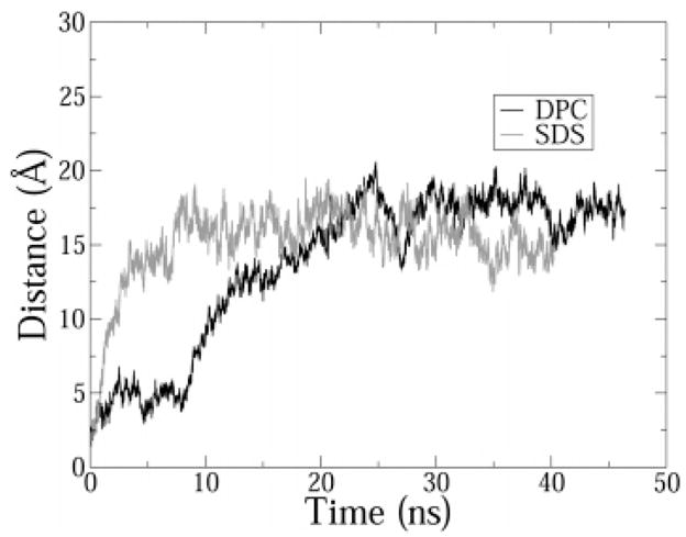
Distance between the center of mass of the micelle and the peptide. Trajectories were sampled every 4 ps. A 5-point average is shown for clarity.
Figure 2.
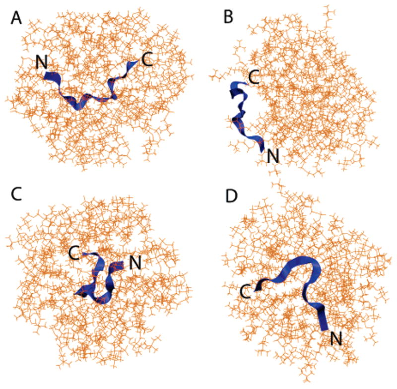
Initial (A and C) and final (B and D) snapshots of the DPC simulation: (A) top view and (C) side view. Snapshots were taken at t = 0 and 45 ns. The N terminus and C terminus have been marked N and C, respectively.
Figure 3.
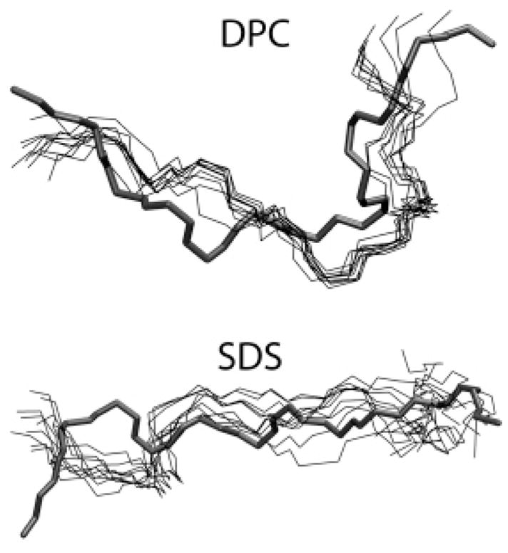
Superimposition of simulations snapshots of the peptide backbone (thin lines) from the last 5 ns of each simulation over the initial structure of the peptide used to start the simulation (thick line). The snapshots were taken every 0.5 ns. The N terminus and C terminus have been marked N and C, respectively.
For the DPC simulation, the average dihedral angles obtained in the simulation are compared to those obtained from all NMR models in Figure 4. Although the absolute values of the (ϕ,ψ) angles from the simulations were quantitatively different from NMR data, they capture the key qualitative structural feature of the peptide: the boat-shaped amphipathic formation. However, in the simulation results, the turns which lead to the boat structure are slightly shifted toward the C terminus, leading to a slightly “skewed-boat”-type of structure (Figure 3). We did not find any backbone–backbone H bonds in the simulation. The dihedral angles of the peptide in the simulations in SDS were similar to those obtained from NMR experiments (data not shown). More importantly, the extent of backbone order predicted by simulations matched experimentally measured order parameter profiles along the peptide backbone. An important difference in the structure of IND in DPC and SDS is that the peptide backbone is more ordered in DPC. Rozek et al. quantify this by using an order parameter as defined by Hyberts et al.30
Figure 4.
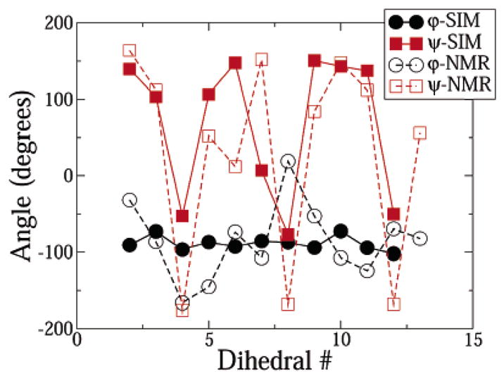
Average dihedral angles of the peptide in the DPC micelle in the simulations and experiments. The experimental data was obtained from the work of Rozek et al.
where N is the total number of structures and αij is a 2D unit vector with phase equal to the dihedral angle αi. Here, i represents the residue number and j stands for the number of the calculated structure. The order parameter formulation clearly defines two limits of an exactly defined angle (S = 1) and a completely random distribution of the angle (S = 0). An easy way to calculate S from the simulations is to use the following semiempirical relationship between S and the standard deviation of the dihedral angle30
where σ(α) is the standard deviation of angle α. In the NMR experiments, the backbone order parameters for angles (ϕ,ψ) are ~1 for residues 3–11 in DPC. The backbone of IND in SDS was predicted to be less ordered compared to that in DPC. In the simulations, the average order parameters obtained for the ψ angle for residues 2–12 are 0.89 and 0.75 for DPC and SDS, respectively (residue 1 was excluded from the average because it has a freely fluctuating N-terminal ψ dihedral). These values indicate that the simulations successfully captured the higher order of the peptide backbone in the DPC micelle. The order parameters for ϕ are comparable in the DPC and SDS simulations. Additionally, in both the DPC and SDS simulations, the order parameters for ϕ are calculated to be greater at the C terminus and N terminus compared to experiments. For residue 2, the simulation value in DPC is 0.95, compared to the experimental value of 0.65. For residues 12 and 13, the simulation values for DPC are 0.98 and 0.99, while the experimental values are 0.48 and 0.77. The experimental order parameters are smaller possibly because not all peptides would be bound to the micelle. This may prevent fluctuations in ϕ leading to higher order parameters in the simulations.
The average root-mean-square (rms) deviation of the backbone C-α atoms from the experimentally obtained structure was 3.4 Å in the case of SDS and 3.9 Å in the case of DPC. Thus, the overall structure of the peptide from the simulations does differ from the experimentally measured structure. The profile of the rms fluctuation from the average structure obtained from the simulations has been shown in Figure 5. The backbone of the peptide deviated significantly more from the average conformation in SDS compared to DPC. This observation is in direct agreement with experiments, where the average rms deviation from the average structure was 0.31 and 0.49 Å in DPC and SDS, respectively.6 The numbers are much lower in experiments because the averages were only calculated for residues 3–11 in DPC and residues 5–11 in SDS. Except for TRP4, all side chains of the peptide fluctuate more in SDS than in the DPC micelle. Again, this is in excellent agreement with experiments, where the average numbers are 0.98 and 1.52 Å in DPC and SDS. Remarkably, just like the simulations, experiments also predict a much higher uncertainty in the location and orientation of the tryptophan-4 residue in DPC micelles.
Figure 5.
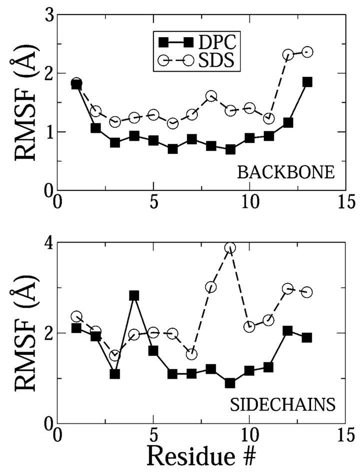
rms fluctuations of the backbone and side-chain heavy atoms in DPC and SDS. The fluctuations were calculated with respect to the ensemble averaged simulation structure.
Orientation of the Tryptophan Side Chains
In NMR experiments in DPC, the tryptophan indole rings were found to be more ordered and packed against the backbone in an approximately parallel fashion. In SDS, on the other hand, the indole rings were extended away from the backbone. This was the main difference between the molecular shape of the peptide in DPC and SDS.6 In order to quantify the orientation of the indole rings, we calculated the angle between the least-squares plane formed by the heavy atoms on the indole ring and the least-squares plane formed by the backbone heavy atoms of the peptide. For the indole rings at residues 4, 6, 8, and 9, the backbone heavy atoms of residues 3–10 were chosen to form the backbone plane. For residue 11, the backbone heavy atoms of residues 3–11 were chosen. The C-terminal and N-terminal backbone atoms were left out from the calculation because these parts of the backbone are not well defined in either micelle. The results of the calculation are presented in Figure 6. The shorter error bars in DPC imply that the tryptophan indole rings were much more ordered in DPC than in SDS, in compliance with experiments. Furthermore, the angle between the planes was smaller in DPC than SDS at all positions except position 8. This observation is entirely consistent with experiments, where the indole ring at position 8 was observed to point away from the backbone in DPC. Notice, however, that the average orientation of the indole rings was not parallel to the backbone in DPC as predicted by experiments. The reason for this is not clear, but the cause might be the differences in the conformation of the backbone in the simulations and experiments. However, it is clear that the indole rings point further away from the backbone in SDS than in DPC, which agrees with experimental measurements. In the following section we propose that cation–π interactions lead to this topology of side chains in DPC.
Figure 6.
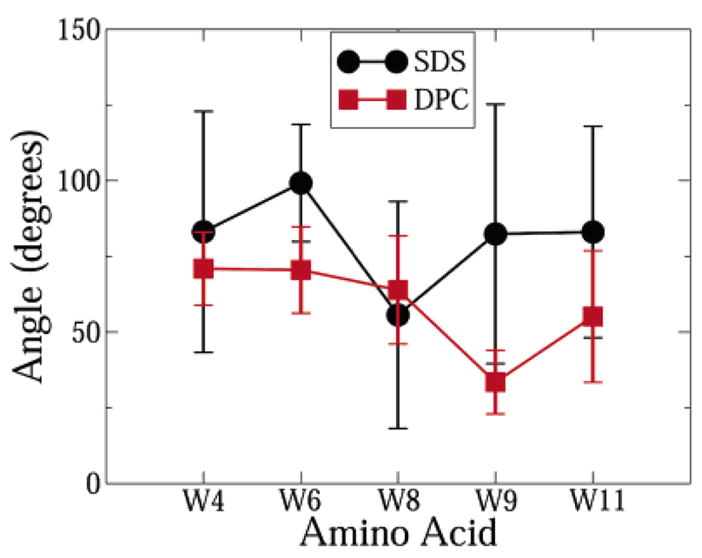
Angle between the least-squares plane of the tryptophan indole rings and the least-squares plane of the peptide backbone atoms.
Role of Individual Amino Acids: Cation–π Interactions
Cation–π interactions between the guanidium ion of arginine and the π-electron cloud from aromatic groups have been known to stabilize protein structures.31 In the DPC micelle–peptide complex, intramolecular cation–π interactions may occur within the peptide, between the indole rings of the tryptophan residues and the positively charged side chains of LYS5, ARG12, and ARG13. Additionally, there is the possibility of formation of cation–π bonds of the tryptophan residues with the cationic choline group on the lipids of the DPC micelle.
In order to calculate cation–π interactions, two parameters were defined. Dπ–cat was defined as the distance between the planes of the cationic group and the planar group, and γ was defined as the angle between them. Cation–π interactions can have two conformations. In the planar conformation, the plane of the aromatic group and the plane of the cationic group stack against each other. For this conformation the γ angle fluctuates between 0–45° and 135–180°. In the T-shaped conformation, the two planes are perpendicular and the angle γ fluctuates between 45° and 145°. In either conformation the typical distance Dπ–cat is about 5 Å.32 Figure 7a is an illustration of a stacked cation–π interaction.
Figure 7.
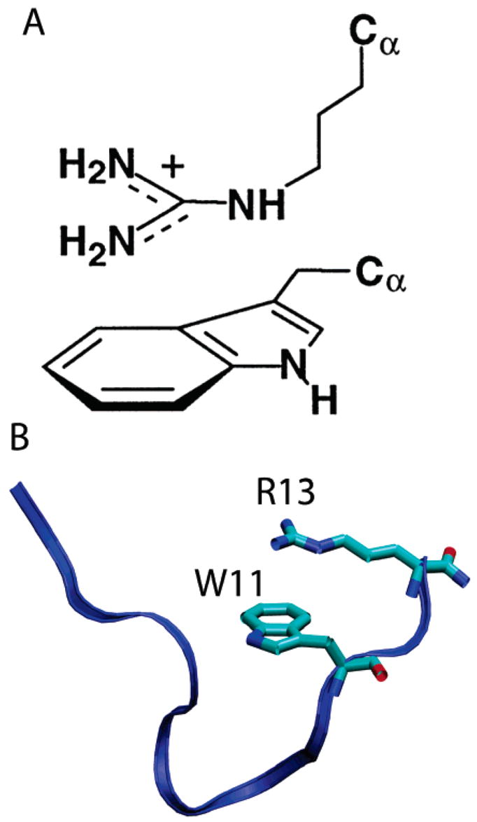
(A) Schematic representation of a stacked (planar) cation–π interaction between a tryptophan residue and a guanidium side chain of arginine. (B) Simulation snapshot (t = 45 ns) of the cation–π interaction between TRP11 and ARG13.
In indolicidin there is a distinct possibility of formation of a cation–π bond between the indole rings of TRP9 and TRP11 and the guanidium ions of ARG12 and ARG13. Because the peptide has an extended structure, TRP4, TRP6, and TRP8 are too far from ARG12 or ARG13 to form cation–π interactions. Furthermore, no cation–π interaction was observed between LYS5 and any of the tryptophan residues. In DPC, the LYS5 side chain always points away from the micelle into the aqueous phase. Distance and angle analysis revealed formation of a single distinct planar cation–π interaction between TRP11 and ARG13 in the DPC micelle. For most of the production period (>30 ns) the angle γ fluctuated between 0° and 45° and the distance Dπ–cat stabilized at 5 Å (Figure 8). The simulation snapshot in Figure 7B shows the stacked geometry of the interaction. In the experimental structure of IND (which was used to start the simulations), the distance Dπ–cat was indeed 5 Å. As the peptide diffused to the micellar interface, the distance increased to about 12 Å. However, once the peptide equilibrated at the micellar interface, Dπ–cat again stabilized to 5 Å and the fluctuation in Dπ–cat progressively diminished with simulation time (Figure 8).
Figure 8.
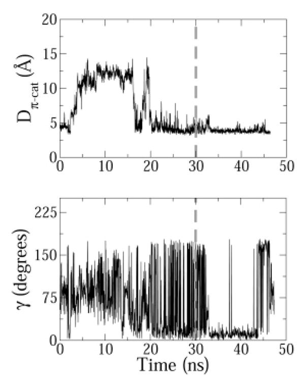
Distance Dπ–cat and angle γ time profiles for the cation–π interaction between TRP11 and ARG13. For clarity purposes, a gray dashed vertical line is drawn at t = 30 ns, the time after which ensemble averages were calculated.
During the ensemble averaging period of the simulation the interaction energy between the indole ring of TRP11 and the guanidium ion of ARG13 was calculated to be −14.83 ± 3.84 kcal/mol, of which the electrostatic component was −12.33 kcal/mol. The TRP11–ARG13 cation–π binding is thus a favorable electrostatic interaction. In perspective, ab initio computational studies of the binding of single Na+ cations to the π face of a naphthalene ring calculated the binding energy to be −32.6 kcal/mol in the optimized geometry configuration.33
Importantly, no such interaction was observed in the SDS micelle. In SDS, the cationic side chains on both arginine residues had a preference for the negatively charged sulfate moieties on SDS molecules and thus did not bind the indole rings of tryptophan. Radial distribution functions (rdfs) of the charged side chains with the sulfate headgroups confirmed this. The rdfs were drawn between the side chain heavy atoms of the amino acid residues and the heavy atoms on the headgroups of DPC and SDS lipids (Figure 9). Because ARG13 was involved in the cation–π interaction in DPC, the ARG13 peak was lower than the ARG12 peak. In SDS, the height of these two peaks was comparable. However, ARG13 had a higher peak in SDS (0.075), compared to the peak in DPC (0.05) because in SDS ARG13 was bound strongly to the lipid headgroups and not to the indole ring of TRP11. In Figure 10 we attempted to give the reader an idea of the relative positions of the headgroups to residues TRP11 and ARG13 in both DPC and SDS. These observations from the simulations offer an interesting interpretation of experimental measurements. It is apparent that the cation–π interaction between TRP11 and ARG13 stabilizes the structure of the peptide in DPC and may also cause the bend at the C terminus. Evidence from the simulations suggests that the interaction is very persistent and would thus lead to stability in the structure of the peptide in DPC. In SDS, on the other hand, the cation–π bond is not formed within the peptide side chains. The indole rings on the tryptophans are thus free to adopt various conformations in space, thus leading to an overall less constrained structure of the peptide in the SDS micelle.
Figure 9.
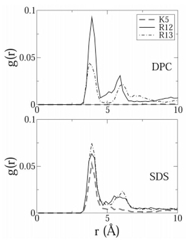
Radial distribution functions between the positively charged side chains of the peptide and the headgroups of SDS and DPC. Hydrogen atoms were excluded from the calculation. The functions were normalized by the number of atoms in the first selection (peptide atoms) and by a density of 0.01.
Figure 10.
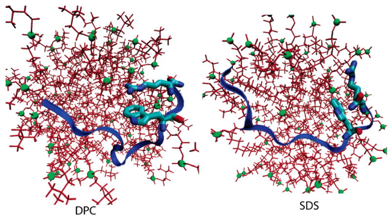
Illustration of the position of TRP11 and ARG13 with respect to the headgroups in DPC (left) and SDS (right). The snapshots were taken at t = 45 ns in DPC and t = 40 ns in SDS. The headgroups are shown as green spheres, and the relative sizes of the molecules are inversely proportional to their distance from the camera (perspective drawing).
The possibility of formation of cation–π interactions between the peptide and micelle was also investigated. A distance matrix between tryptophan side chains and the choline headgroups of each DPC molecule was constructed. All TRP–DPC pairs, which had a distance below the cutoff value of 10 Å at any time during the simulation, were scanned for cation–π interactions using the distance and angle criteria described earlier. The only pair to satisfy the criteria of was TRP4–DPC14 pair (the DPC molecules were numbered arbitrarily). For one-half of the production period, the Dπ–cat distance between TRP4 and DPC14 was about 5 Å (Figure 11). The angle γ is not well defined for the DPC14–W4 pair because the choline group has a tetrahedral geometry. Nevertheless, to make the analysis complete, a least-squares plane which passes through the centroid of the choline group was calculated and γdefined as the angle between this plane and the plane of the guanidium. The angle fluctuated between 45° and 145° but does not necessarily indicate a T-shaped cation–π interaction because γ is ill defined. The distance Dπ–cat was more than 5 Å for about one-half of the sampling period (Figure 11), indicating that this cation–π interaction may be transitional. Nevertheless, there is a distinct possibility that the TRP4–DPC14 cation–π interaction may also stabilize the N-terminal bend of indolicidin near the DPC micelle.
Figure 11.
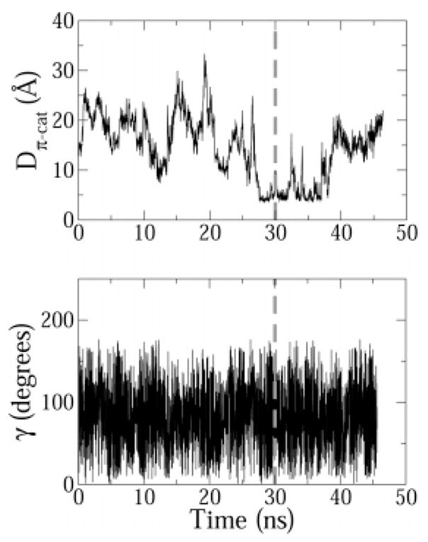
Distance Dπ–cat and angle γ time profiles for the cation–π interaction between TRP4 and DPC14. For clarity purposes, a gray dashed vertical line is drawn at t = 30 ns, the time after which ensemble averages were calculated.
Radial distribution functions of the tryptophan side chains with the micellar core revealed that in DPC, TRP8 and TRP9 penetrated deepest into the micelle (Figure 12). TRP11 did not penetrate as deep because it was involved in a cation–π interaction with ARG13. In SDS, on the other hand, TRP11 also penetrated into the micelle because there was no cation–π interaction. Interestingly, the rdfs indicate that TRP4 did not insert into the membrane core in either SDS or DPC. In DPC, this allowed the indole ring of DPC to form a cation–π interaction with a DPC headgroup choline moiety.
Figure 12.
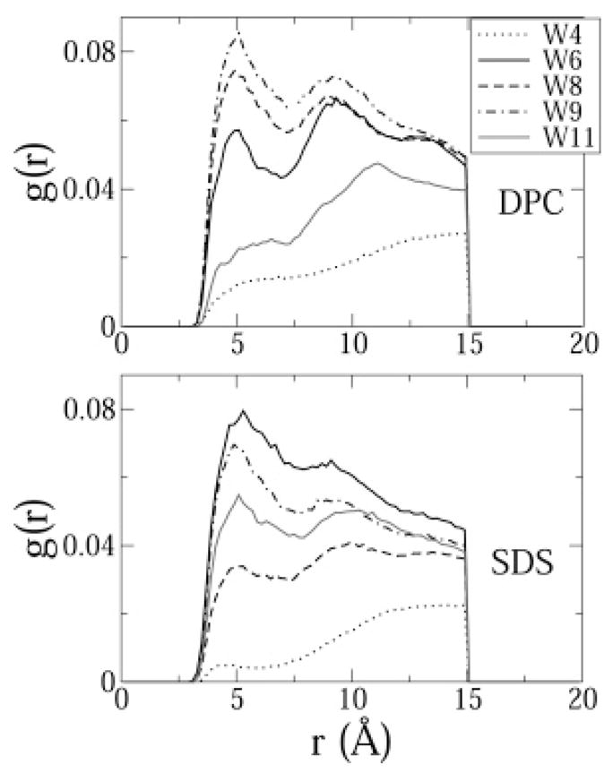
Radial distribution functions between the indole rings on the tryptophan residues and the hydrocarbon tails of SDS and DPC. Hydrogen atoms were excluded from the calculation. The functions were normalized by the number of atoms in the first selection and by a density of 0.01.
Results from the W11A Mutant Simulation
To further strengthen the argument that the TRP11–ARG13 cation–π interaction has a significant influence on the structure of the peptide in DPC, a simulation of the W11A mutant peptide was carried out in the DPC micelle. The W11A peptide diffused to the surface of the DPC micelle in ~38 ns. The simulation was carried out for a further 12 ns for a total simulation time of 50 ns. Ensemble averages were drawn from the last 10 ns of the simulation. For the sake of brevity, we will only show data that directly compares the structural characteristics and conformational stability of W11A in DPC vs that of the stability of IND in the DPC and the SDS simulation. In Table 1 we summarized some average structural properties of the peptide in the three simulations. In general, the W11A mutation led to structural instability of the peptide in DPC. The following measurements provide adequate evidence that the TRP11–ARG13 cation–π interaction is critical for the well-defined amphipathic structure of the indolicidin peptide in DPC. (1) The average order parameters of the backbone dihedral angles were lower for W11A than for IND in DPC. (2) Although the average rmsf of the peptide backbone was only slightly higher for W11A than for IND, the average rmsf of residues 8–13 is significantly higher while the average rmsf of residues 1–5 is slightly lower in W11A than in IND. These data indicate that loss of the boat-shaped structure of W11A in DPC is driven by a disordering of residues 8–13. (3) The orientation of the tryptophan side chains had a greater average fluctuation in W11A than for indolicidin in DPC. In this respect, the W11A peptide structure was similar to the structure of indolicidin in SDS. Like in SDS (Figure 6), the indole rings of TRP4, TRP8, and TRP9 were oriented away from the peptide backbone in W11A (data not shown).
TABLE 1.
Comparison of Ensemble Averaged Structural Properties of the Peptide in the Three Simulations, Averaged over the Entire Sequencea
| Property | DPC | W11A | SDS |
|---|---|---|---|
| 〈order parameter (φ)〉 | 0.986 | 0.982 | 0.983 |
| 〈order parameter (ψ)〉 | 0.889 | 0.760 | 0.754 |
| 〈RMSD from NMR structure〉 (Å) | 3.912 | 4.029 | 3.532 |
| 〈backbone RMSF〉: entire sequence (Å) | 1.03 | 1.13 | 1.51 |
| 〈backbone RMSF〉: residues 1–5 (Å) | 1.09 | 0.92 | 1.38 |
| 〈backbone RMSF〉: residues 8–13 (Å) | 1.11 | 1.48 | 1.73 |
| 〈fluctation in orientation of W4, W6, W8, and W9〉 | 13.50 | 29.75 | 34.75 |
Order parameters were averaged over residues 2–12.
In Figure 13 the backbone traces from 10 simulation snapshots (taken every 50 ps for the last 5 ns) of the W11A-DPC simulation have been aligned to the starting conformation. As described above, the W11A mutation led to significant disordering of the peptide C terminus. The well-defined bend at the C terminus, (and hence the boat-shaped structure), which was one of the hallmarks of the peptide structure in DPC, was thus lost in the W11A mutant. Furthermore, the average interaction energy between the ALA11 and ARG13 side chain was unfavorable: 1.33 ± 1.04 kcal/mol.
Figure 13.
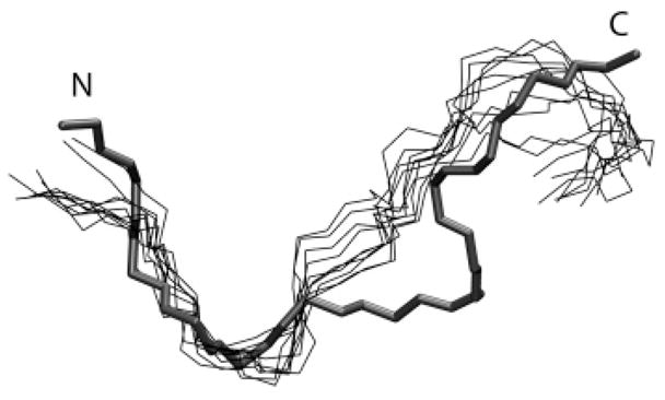
Superimposition of simulation snapshots of the peptide backbone (thin lines) from the last 5 ns of the W11A simulation over the initial structure of the peptide used to start the simulation (thick line). The snapshots were taken every 0.5 ns. The N terminus and C terminus have been marked N and C, respectively. The initial structure for the simulation was obtained after backbone-restrained minimization of the pdb-derived structure of indolicidin in DPC.
Discussion
Indolicidin is a fascinating antimicrobial peptide because of its novel tryptophan-rich sequence and because it lacks well-defined secondary structural elements. Despite its small length, its extended structure can span the width of the lipid bilayer and at high enough concentrations the peptide can cause leakage of the contents of large unilamellar vesicles. Deduction of the structure of IND in DPC and SDS micelles from NMR experiments6 provided the basis for a detailed structural analysis of the possible mechanism of action of the peptide. However, the experiments did not elaborate upon the forces which drive folding of IND into specific, different structures in DPC and SDS. In the current work, we attempted to identify specific lipid–peptide and peptide–peptide interactions that lead to the folding of the peptide near the interface.
The key differences between the structure of IND in DPC and SDS are its better-defined shape and the greater order of the tryptophan side chains in DPC. Additionally, the relative orientation of the tryptophan side chains is different in DPC and SDS micelles. The following observations from the simulations agree with experimental measurements on all these counts. (1) The order parameter of the backbone dihedral angles was smaller in SDS. (2) The backbone rms fluctuation from the average structure was higher in SDS. (3) The tryptophan side chains were oriented more parallel to the backbone in DPC compared to SDS. NMR measurements showed that TRP8 was an exception which was oriented away from the backbone in DPC. In the simulations too, TRP8 was oriented perpendicular to the backbone. (4) The fluctuation in the orientation of the tryptophan indole rings was higher in SDS.
The average root-mean-squared deviation of the simulated conformations from the native structure is not negligible: 3.9 Å in DPC and 3.4 Å in SDS. Additionally, the backbone dihedral angles for a few residues are significantly different, both in DPC and in SDS. Thus, there are appreciable quantitative differences in the simulated conformations and the peptide conformations predicted from experiments. However, even in the NMR experiments,6,14 the peptide structure was well defined only for 69% of the residues (residues 3–11) in DPC and 53% of the residues (residues 5–11) in SDS. In light of the inherently high conformational freedom of the indolicidin peptide, the simulations have been remarkably successful in accurately reproducing several structural and dynamic features of the peptide as discussed in the previous paragraph. Moreover, the amphipathic structure of indolicidin in DPC and its extended structure in SDS are qualitatively very well reproduced in the simulations.
Importantly, the simulations were started with the peptide initially placed along a micelle diameter and still converged to the experimentally observed conformations of a surface-bound state.
The tryptophan residues in indolicidin are expected to lower the conformational free energy of the micelle-bound peptide by hydrophobic interactions with the micelle’s hydrophobic core. Indeed, radial distribution functions (Figure 12) indicate that TRP6, TRP8, and TRP9 were embedded in the micellar core both in DPC and in SDS. In DPC, TRP11 was sequestered by ARG13 and thus did not insert into the micelle while it did so in SDS. Hydrophobic interactions of the peptide with the micelle should have a significant impact on the structure of the peptide. However, these interactions are similar in both DPC and SDS micelles. The differences in the structure of IND in DPC and SDS micelles alone cannot be explained by hydrophobic interactions.
Our calculations indicate that cation–π interactions stabilize the structure of IND in the DPC micelle. We observed formation of a highly persistent cation–π interaction between the indole ring of TRP11 and the guanidium group of ARG13. To confirm the importance of the TRP11–ARG13 cation–π bond, we carried out a simulation of the W11A mutant in a DPC micelle. Compared to indolicidin, the mutant had significantly increased rms fluctuations and backbone dihedral angle order parameters, especially for residues 8–13, which are spatially near the point of mutation. Importantly, W11A had an extended, ill-defined structure at the C terminus, and the peptide no longer adopted the boat-shaped conformation, which was observed for the native peptide. The results from the W11A simulation confirm beyond doubt that molecular interactions involving TRP11 have a significant contribution to peptide structural stability. As described earlier, simulations of native indolicidin demonstrate that this stabilizing influence is mediated by the cation–π interaction with ARG13. Staubitz et al.20 synthesized various IND analogues and measured their minimum inhibitory concentrations (MIC) against M. luteus. Indeed, they found that IND analogues where TRP11 was replaced by ALA11 had an MIC 400% of that of the native peptide. Similar mutations to the tryptophan residues at positions 6, 8, and 9 only caused a 200% increase in MIC (Table 2). Mutation of ARG12 to A12 led to no reduction in antibacterial activity, but a mutation of ARG13 to A13 led to a 50% reduction in activity. However, a 50% reduction in activity was also achieved by single-residue alanine mutants of residues LYS5, TRP6, TRP8, and TRP9. The experiments of Staubitz and co-workers20 thus confirmed the importance of the TRP11–ARG13 cation–π with respect to the drastic reduction in the activity of the W11A mutant, but the reduction in the activity due to the R13A mutation was replicated by mutations at other points in the sequence as well.
TABLE 2.
Comparison of MIC (μM) against M. luteus (Staubitz et al.20)
| ILPWKWPWWPWRR | 0.4 |
| ILPWKWPWWPARR | 1.6 |
| ILPWKWPWAPWRR | 0.8 |
| ILPWKWPAWPWRR | 0.8 |
| ILPWKAPWWPWRR | 0.4 |
| ILPAKWPWWPWRR | 0.4 |
| ILPWKWPWWPWRA | 0.8 |
| ILPWKWPWWPWAR | 0.4 |
The simulations suggest that there is a direct correlation between the TRP11–ARG13 interaction and the structural stability of the peptide in DPC micelles. However, owing to the uncertainty in the mechanism of antimicrobial action of indolicidin, care must be taken while making a direct correlation between the specific structure of the peptide and its biological activity. The boat-shaped conformation of IND is biologically relevant because it probably influences the translocation of IND through membranes. Once the peptide diffuses to the cytoplasm, however, it may have a different conformation in its active state (when bound to the intracellular target) or when floating in the cytoplasm. Therein, the inherent structural flexibility of IND may facilitate binding to various targets. A mutant of IND where all proline residues were replaced by alanine residues was found to be more active against gram-positive bacteria than the native peptide.19 Because this mutant had an α-helical structure, it may be argued that the boat-shaped conformation of the native peptide may not be biologically indispensable to function. However, the drastically different structure and significantly different sequence (23%) of the mutant may cause it to insert into membranes differently, have different intracellular targets than indolicidin, and thus operate by an entirely distinct mechanism of action. To summarize, based on the already available experimental measurements and our simulations it is difficult to determine the biologically relevant conformation of IND if it binds to an intracellular target.
Cation–π interactions have been known to stabilize protein structures, but to the best of our knowledge, this is the first time that these interactions have been shown to play an important role in the structural stability of small antimicrobial peptides. The good agreement between NMR data and the simulations, especially near the C terminus, is further evidence of the possible involvement of the cation–π interaction. While this article was being prepared, Petersen et al.34 suggested that peptide–lipid cation–π interactions were important in the binding of the gramicidin peptide to POPE and POPC lipids bilayers and for protein–lipid interactions in general. In the simulations a transient cation–π interaction was detected between TRP4 and a DPC molecule which might help the peptide anchor to the DPC micelle (or to zwitterionic lipids in general).
On the basis of the boat-shaped structure of IND in DPC micelles, Rozek et al.6 suggested two possible orientations of IND in lipid bilayers. The peptide could either be in a transmembrane orientation, with the positive charges projecting from the opposite ends of the bilayer, or insert into one leaflet of the bilayer in a boat-shaped conformation, with the charged ends projecting out on the same side of the bilayer. Although the current study provides useful molecular insights into the structure of IND near micelles, it is not adequate to provide a sufficiently detailed model for the interaction of the peptide with lipid bilayers. Although DPC lipids have a choline headgroup similar to membrane phospholipids, there is a distinct possibility that the curvature of the micelle might influence the way the peptide positions itself near the interface and hence its overall structure. The obvious next step will be to implement simulations of the peptide in lipid bilayers. Meanwhile, experimental measurements of the structure and orientation of indolicidin in bilayers will be valuable.
Acknowledgments
This work was supported by a grant from the NIH (GM 070989). Computational support from the Minnesota Supercomputing Institute (MSI) is gratefully acknowledged. This work was also partially supported by National Computational Science Alliance under MCB030027P.
References and Notes
- 1.Selsted ME, Novotny MJ, Morris WL, Tang YQ, Smith W, Cullor JS. J Biol Chem. 1992;267:4292. [PubMed] [Google Scholar]
- 2.Lee DG, Kim HK, Kim SA, Park Y, Park SC, Jang SH, Hahm KS. Biochem Biophys Res Commun. 2003;305:305. doi: 10.1016/s0006-291x(03)00755-1. [DOI] [PubMed] [Google Scholar]
- 3.Falla TJ, Hancock REW. Antimicrob Agents Chemother. 1997;41:771. doi: 10.1128/aac.41.4.771. [DOI] [PMC free article] [PubMed] [Google Scholar]
- 4.Robinson WE, Jr, McDougall B, Tran D, Selsted ME. J Leukocyte Biol. 1998;63:94. doi: 10.1002/jlb.63.1.94. [DOI] [PubMed] [Google Scholar]
- 5.Krajewski K, Marchand C, Long YQ, Pommier Y, Roller PP. Bioorg Med Chem Lett. 2004;14:5595. doi: 10.1016/j.bmcl.2004.08.061. [DOI] [PubMed] [Google Scholar]
- 6.Rozek A, Friedrich CL, Hancock RE. Biochemistry. 2000;39:15765. [PubMed] [Google Scholar]
- 7.Falla TJ, Karunaratne DN, Hancock REW. J Biol Chem. 1996;271:19298. doi: 10.1074/jbc.271.32.19298. [DOI] [PubMed] [Google Scholar]
- 8.Ladokhin AS, Selsted ME, White SH. Biophys J. 1997;72:794. doi: 10.1016/s0006-3495(97)78713-7. [DOI] [PMC free article] [PubMed] [Google Scholar]
- 9.Schibli DJ, Epand RF, Vogel HJ, Epand RM. Biochem Cell Biol. 2002;80:667. doi: 10.1139/o02-147. [DOI] [PubMed] [Google Scholar]
- 10.Shaw JE, Alattia JR, Verity JE, Prive GG, Yip CM. J Struct Biol. 2006;154:42. doi: 10.1016/j.jsb.2005.11.016. [DOI] [PubMed] [Google Scholar]
- 11.Ha TH, Kim CH, Park JS, Kim K. Langmuir. 2000;16:871. [Google Scholar]
- 12.Bahng MK, Cho NJ, Park JS, Kim K. Langmuir. 1998;14:463. [Google Scholar]
- 13.Subbalakshmi C, Sitaram N. FEMS Microbiol Lett. 1998;160:91. doi: 10.1111/j.1574-6968.1998.tb12896.x. [DOI] [PubMed] [Google Scholar]
- 14.Hsu CH, Chen C, Jou ML, Lee AYL, Lin YC, Yu YP, Huang WT, Wu SH. Nucleic Acids Res. 2005;33:4053. doi: 10.1093/nar/gki725. [DOI] [PMC free article] [PubMed] [Google Scholar]
- 15.Sitaram N, Subbalakshmi C, Nagaraj R. Biochem Biophys Res Commun. 2003;309:879. doi: 10.1016/j.bbrc.2003.08.095. [DOI] [PubMed] [Google Scholar]
- 16.Zhao H, Kinnunen PK. Antimicrob Agents Chemother. 2003;47:965. doi: 10.1128/AAC.47.3.965-971.2003. [DOI] [PMC free article] [PubMed] [Google Scholar]
- 17.Osapay K, Tran D, Ladokhin AS, White SH, Henschen AH, Selsted ME. J Biol Chem. 2000;275:12017. doi: 10.1074/jbc.275.16.12017. [DOI] [PubMed] [Google Scholar]
- 18.Subbalakshmi C, Bikshapathy E, Sitaram N, Nagaraj R. Biochem Biophys Res Commun. 2000;274:714. doi: 10.1006/bbrc.2000.3214. [DOI] [PubMed] [Google Scholar]
- 19.Friedrich CL, Rozek A, Patrzykat A, Hancock RE. J Biol Chem. 2001;276:24015. doi: 10.1074/jbc.M009691200. [DOI] [PubMed] [Google Scholar]
- 20.Staubitz P, Peschel A, Nieuwenhuizen WF, Otto M, Gotz F, Jung G, Jack RW. J Pept Sci. 2001;7:552. doi: 10.1002/psc.351. [DOI] [PubMed] [Google Scholar]
- 21.Rozek A, Powers JP, Friedrich CL, Hancock RE. Biochemistry. 2003;42:14130. doi: 10.1021/bi035643g. [DOI] [PubMed] [Google Scholar]
- 22.Wymore T, Gao XF, Wong TC. J Mol Struct. 1999;485–486:195. [Google Scholar]
- 23.Jorgensen WL, Chandrasekhar J, Medura JD, Impey RW, Klein ML. J Chem Phys. 1983;79:926. [Google Scholar]
- 24.Brooks BR, Bruccoleri RE, Olfson BD, States DJ, Swaminathan S, Karplus K. J Comput Chem. 1983;4:187. [Google Scholar]
- 25.Hoover WG. Phys Rev A. 1985;31:1695. doi: 10.1103/physreva.31.1695. [DOI] [PubMed] [Google Scholar]
- 26.Feller SE, Zhang Y, Pastor RW, Brooks BR. J Chem Phys. 1995;103:4613. [Google Scholar]
- 27.Essmann U, Perera L, Berkowitz ML, Darden T, Lee H, Pedersen LG. J Chem Phys. 1995;103:8577. [Google Scholar]
- 28.Khandelia H, Kaznessis Y. Peptides. 2005;26:2037. doi: 10.1016/j.peptides.2005.03.058. [DOI] [PubMed] [Google Scholar]
- 29.Karpen ME, Tobias DJ, Brooks CL., III Biochemistry. 1993;32:412. doi: 10.1021/bi00053a005. [DOI] [PubMed] [Google Scholar]
- 30.Hyberts SG, Goldberg MS, Havel TF, Wagner G. Protein Sci. 1992;1:736. doi: 10.1002/pro.5560010606. [DOI] [PMC free article] [PubMed] [Google Scholar]
- 31.Burley SK, Petsko GA. FEBS Lett. 1986;203:139. doi: 10.1016/0014-5793(86)80730-x. [DOI] [PubMed] [Google Scholar]
- 32.Aliste MP, MacCallum JL, Tieleman DP. Biochemistry. 2003;42:8976. doi: 10.1021/bi027001j. [DOI] [PubMed] [Google Scholar]
- 33.Mecozzi S, West AP, Jr, Dougherty DA. PNAS. 1996;93:10566. doi: 10.1073/pnas.93.20.10566. [DOI] [PMC free article] [PubMed] [Google Scholar]
- 34.Petersen FN, Jensen MO, Nielsen CH. Biophys J. 2005;89:3985. doi: 10.1529/biophysj.105.061804. [DOI] [PMC free article] [PubMed] [Google Scholar]


