Abstract
An empirical model is developed to capture the electrostatics of finite-length single-walled armchair carbon nanotubes for biological applications. Atomic partial charges are determined to match the electrostatic potential field computed at the B3LYP/6-31G* level of density functional theory, and a tight-binding Hamiltonian is selected which permits one to reproduce the dielectric properties in good agreement with density functional theory results. The new description is applied to study movement of a water molecule through a finite-length nanotube channel in order to demonstrate the method’s feasibility. We find that atomic partial charges on the tube edges dominate the interaction between the nanotube and the entering water molecule, while the polarization of the nanotube lowers the electrostatic energy of the water molecule significantly inside the tube.
Introduction
Carbon nanotubes (CNTs), as building blocks of nanotechnology, hold great promise for biological applications, in particular, as molecular channels conducting water,1–4 protons,5,6 ions,7 polymers,8 and nucleic acids.9 In principle, molecular dynamics (MD) simulations serve as a powerful tool to investigate and characterize such systems. For example, MD simulation studies predicted that water molecules are able to enter the hydrophobic interior of single-walled carbon nanotubes (SWNTs) forming well-organized structures,1–4 which were later verified by neutron scattering experiments.10 Despite the successful predictions, the nanotube models used in existing classic MD simulations provide an incomplete description of nanotube electrostatics and overlook nanotube polarizability, which may compromise accurate modeling of transport through SWNT channels. First of all, existing models employ non-saturated open-ended SWNTs with each carbon atom assumed to be neutral. However, density functional theory (DFT) calculations11 on open-ended finite-length SWNTs suggest that dramatic geometry reconstruction occurs at the non-saturated end by forming C-C triple bonds, and an appreciable local dipole moment appears at the tube edge. At the hydrogen-saturated end, one also needs to account for edge dipole moments.11 Naturally, the edge dipole interacts with the environment and affects the translocation of molecules. Second, since the π-electrons of SWNTs respond strongly to external fields, neglecting their dielectric screening effect in the MD simulations is not justified. It is known that the dielectric response of a SWNT stabilizes charged species inside the tube during their transport6,12 or during chemical reactions.13
Attempts have been made to employ ab initio MD methods5,6 to study water and proton transport through SWNTs, but the computational cost limits their applications in MD settings. Recently, a third-nearest-neighbor (third-NN) tight-binding (TB) approach12 was proposed by the authors to calculate the dielectric response of finite-length armchair SWNTs. Implementing this method into MD simulations provides an efficient way to take into account SWNT polarizability. However, the reliability of the TB model has not been fully examined, for example, by comparing its results with those of first principle methods. Furthermore, the atomic partial charges assumed in empirical MD force fields need to be adjusted as well. Thus, it is highly desirable to develop a SWNT model for atomic partial charges and polarization effects that can be used in conjunction with MD simulations.
In this study, we propose a saturated SWNT model, since chemically shortened SWNTs are saturated by carboxylic acid groups at the open ends,14 and since the edge-termination also prevents large geometry reconstruction originating from the dangling bonds of edge carbon atoms. For this purpose, we adopt a simplified SWNT model with hydrogen termination. As we demonstrate below, optimization of ideal hydrogen-terminated SWNTs only slightly perturbs the overall structure. In our model, the atomic partial charges are parameterized to reproduce the DFT electrostatic potential field. For short tube segments, atomic partial charges are suggested for both ideal and optimized geometries. For long tube segments, which are too demanding for DFT calculations, empirical expressions are derived to evaluate partial charges. The dielectric response of SWNTs is treated through a self-consistent third-NN TB Hamiltonian, for which good agreement with DFT predictions is seen for key properties including band gaps and dielectric constants.
The paper is arranged as follows. We first introduce the partial charge fitting scheme and the TB Hamiltonian. Then atomic partial charges of SWNT segments at various lengths are presented. Next, we compare band gap and parallel (perpendicular) dielectric constants from the TB method and DFT to quantify the reliability of the TB method in describing the polarizability. Corrections arising from hydrogen termination and the SWNT curvature are discussed. Finally, we study the interaction between a water molecule and a short ideal (6,6) nanotube segment and summarize our conclusions.
Model and Methods
An ideal SWNT can be considered a hollow cylinder rolled up from a single graphene layer with lattice constant .15 Different SWNTs are classified according to their chiral indices (n, m). The system under study consists of finite-length (6,6) SWNT segments terminated by hydrogen atoms. Segments with different lengths are labeled by l, the number of carbon atom sections. C-C and C-H bond lengths in the ideal geometry are fixed at dCC = 1.44 Å15 and dCH = 1.09 Å.16 Single point calculations and geometry optimizations are carried out using the DFT (B3LYP/6-31G*17) model implemented in the Gaussian 03 package.18 Symmetry (D6h/D6d) constrains are always enforced unless an external field is applied.
Millefiori et al.19 investigated the static dipole polarizability of ethene, benzene and naphthalene by ab initio and DFT methods using a variety of basis sets. They found excellent agreement between the experimental data and DFT calculations adopting the B3LYP exchange-correlation functional in conjunction with suitably extended and diffuse basis sets, e.g., the augmented correlation-consistent polarized valence double-zeta20 and the Huzinaga split valence21 basis sets. To estimate the performance of the B3LYP/6-31G* model in describing the dielectric property of arene molecules, we calculated the dipole polarizability of benzene and naphthalene. Compared with experimental values, the average polarizability of benzene and naphthalene were underestimated by 19% and 15%, respectively. With less than 10% error coming from the in-plane components, the major deviation lies in the out-of-plane component, which is attributed to a lack of diffuse functions in the basis set. For SWNTs, however, the polarization is mainly due to charge redistribution within the cylindrical surface, and therefore is less dependent on diffuse functions of basis sets. In addition, the B3LYP/6-31G* model is found to reproduce well the experimental geometry of a fullerene derivative.22
Determination of atomic partial charges for the system of interest is an essential ingredient in modern approaches for empirical force field development. As the atomic partial charge is not an experimentally observable quantity, various schemes are adopted by different force field approaches in use today.23–25 In the present study, atomic partial charges of SWNT segments are determined under the restricted electrostatic potential (RESP) fitting scheme.26,27 This scheme employs a grid-fitting procedure to match the surrounding electrostatic potential (ESP) built by atomic partial charges to the ESP from quantum chemistry calculations. Adopting RESP charges also ensures compatibility of our nanotube model to the Amber 94 force field,23 which interprets atomic partial charges in the same way.
RESP charges of ideal and optimized (6,6) nanotube segments from 2 to 12 sections are obtained as follows. ESP points are generated from B3LYP/6-31G* level single point calculations, where tight convergence is always required. Six concentric ESP layers and a density of eight points per Å 2 are chosen to ensure sufficient sampling. A standard two-step fitting procedure26 is then applied, where only the charges on the hydrogen atoms are not restrained and symmetry constrain is forced in the second step. This model is referred to below as model α, and notations idl_α and opt_α stand for model α of ideal and optimized geometry, respectively. We also propose a simple 3-parameter RESP scheme, referred to as model β, to efficiently parameterize partial charges for even longer SWNT segments without degrading the quality of the electrostatics of our model. For SWNTs with more than four sections, equal partial charges are enforced in model β on carbon atoms other than H, C1 and C2 (see Fig. 1) at step two of the fitting procedure. As a result, there are only three independent variables under the charge neutrality condition. The remainder of the fitting scheme is the same as for model α.
Figure 1.
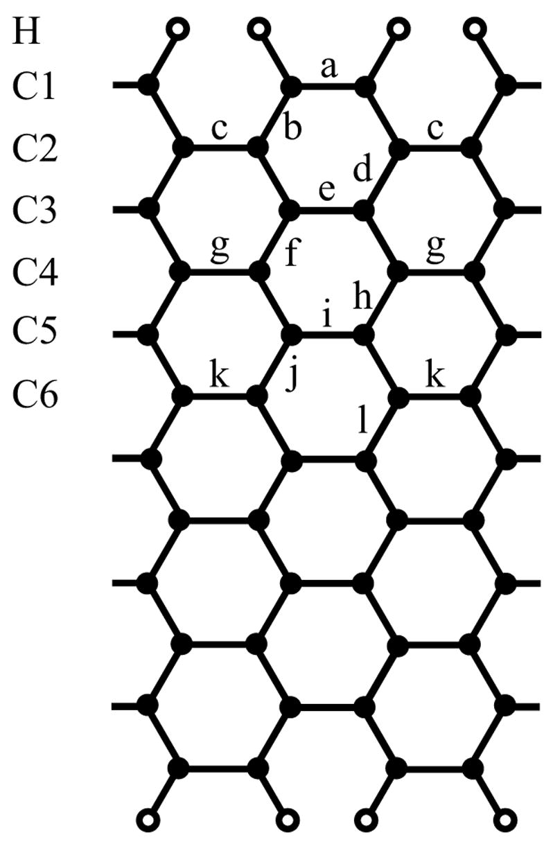
Schematic view of a 12-section armchair SWNT. Carbon atoms are shown as solid circles and hydrogen atoms as open circles.
The quality-of-fit is measured by the relative root mean square deviation (RRMSD). Define Vi as the quantum chemistry ESP at grid point i, and V̂i as the one calculated from RESP charges. The RRMSD is given by26
| (1) |
Another figure of merit of the RESP scheme is the lowest non-zero multipole moment. Since the SWNT segments in our study are charge neutral and non-polar, net charge and dipole moments vanish. We compare axial quadrupole moments, Qzz, obtained from DFT and RESP methods. Due to the symmetry of the system, the traceless quadrupole moment obeys the relationship, , while off-diagonal quadrupole moments vanish. Therefore, Qzz characterizes the quadrupole moment entirely.
The dielectric properties of the SWNTs were investigated with both DFT (B3LYP) and semi-empirical (self-consistent third-NN TB) methods. In the TB model, we consider only the π-electrons and neglect effects of hydrogen termination and curvature. Denoting by i the π-orbital at the i-th carbon atom, the single-electron self-consistent TB Hamiltonian is given by
| (2) |
where pairs < i, j > are confined to include up to third nearest neighbors. γi,j are the hopping integrals derived previously28 with values γ0 = −2.97 eV, γ1 = −0.073 eV, γ2 = −0.33 eV for the first-, second- and third-NN hopping integrals, respectively. Uext is the external potential, and Uint is the electron-electron Coulomb interaction from a non-uniform charge distribution, which is expressed in a smoothed form by . U0 = 14.6 eV29 is the on-site Hubbard energy, and δqj = qj − 1 is the change of occupation number of π-electrons from the bulk value at site j, where qj is associated with the projection of occupied molecular orbitals on the jth atomic orbital. To ensure self-consistency of charges and total potential, the Hamiltonian in Eq. 2 is diagonalized iteratively. An initial guess of δqj is first assumed, and Eq. 2 is then solved to yield another set of δqj constructed from the eigenvectors. At the next iteration, δqj is obtained from a linear combination of values at the previous and current iterations. The procedure continues until charges and total potential converge.
The energy gaps between the levels for the highest occupied molecular orbital (HOMO) and the lowest unoccupied molecular orbital (LUMO) are computed as a function of the tube length. The dielectric behavior is probed by turning on a uniform electric field parallel and perpendicular to the nanotube axis and extracting corresponding changes in the electrostatic potential profile on the nanotube wall. We find that inclusion of non-zero overlap integrals increases the overall asymmetry of the electron band and hole band, while exerting little influence on the low energy properties. A difference of about 5% is found for both the band gap and the dielectric constant when a non-orthogonal basis is used. For the sake of simplicity, we neglect the overlap integrals in the following TB description.
Atomic Partial Charges
Optimized structures were obtained for SWNTs with 2 to 12 sections. The bond ordering, as defined earlier,22 is shown in Fig. 1. Bond lengths for optimized structures with l = 2, 3, 11 and 12 are listed in Table 1, and we refer the reader to the literature22 for structures with 4 to 10 sections. The major change in the geometry occurs at the open ends with bond α contracting from 1.44 Å to 1.36 – 1.39 Å, while the lengths of other C-C bonds, for most cases, change by less than 0.03 Å. Except for the cases l = 2 and 6, where dCH measures 1.089 Å and 1.086 Å, respectively, the optimized C-H bond length is 1.085 Å.
Table 1.
Bond Lengths (in Å) of Optimized (6,6) SWNTs with 2, 3, 11, and 12 Sections
| la | a | b | c | d | e | f | g | h | i | j | k | l |
|---|---|---|---|---|---|---|---|---|---|---|---|---|
| 2 | 1.357 | 1.455 | ||||||||||
| 3 | 1.390 | 1.410 | 1.491 | |||||||||
| 11 | 1.370 | 1.433 | 1.441 | 1.420 | 1.436 | 1.431 | 1.413 | 1.434 | 1.421 | 1.424 | 1.432 | |
| 12 | 1.380 | 1.420 | 1.459 | 1.418 | 1.432 | 1.436 | 1.420 | 1.421 | 1.439 | 1.420 | 1.428 | 1.433 |
RESP charges of both ideal and optimized structures are summarized in Table 2. As mentioned in the previous section, idl and opt denote ideal and optimized structures, while α and β denote the standard and the 3-parameter RESP fitting schemes. A distinct feature noted from Table 2 is that partial charges accumulate on the edge atoms. As a hydrogen atom has a lower electronegativity than a carbon atom,30 each hydrogen atom loses 0.13 – 0.14 electrons in model idl_α and 0.10 – 0.12 electrons in model opt_α as a result of local charge transfer. The magnitude of partial charges in the middle of the SWNTs decays quickly and is usually an order of magnitude smaller than the edge charges. The RRMSD values increase slightly with the length of segments and are generally larger for optimized structures. At l = 12, the RRMSD values are 0.1743 and 0.2118 for idl_α and opt_α, respectively. We note that a RRMSD value between 0.1 and 0.3 is typical for small alcohol and amine molecules.27
Table 2.
RESP Charges for (6,6) SWNTs of Different Lengths
| l | model a | H | C1 | C2 | C3 | C4 | C5 | C6 | RRMSD |
|---|---|---|---|---|---|---|---|---|---|
| 2 |
idl_α
opt_α |
0.1286
0.1061 |
−0.1286
−0.1061 |
0.1664
0.1873 |
|||||
| 3 |
idl_α
opt_α |
0.1252
0.1047 |
−0.1534
−0.1161 |
0.0563
0.0228 |
0.1592
0.1808 |
||||
| 4 |
idl_α
opt_α |
0.1432
0.1158 |
−0.1981
−0.1503 |
0.0549
0.0346 |
0.1321
0.1800 |
||||
| 5 |
idl_α(β)
opt_α(β) |
0.1354
0.1142 |
−0.1700
−0.1387 |
0.0121
0.0098 |
0.0450
0.0294 |
0.1419
0.1790 |
|||
| 6 |
idl_α(β)
opt_α(β) |
0.1361
0.1131 |
−0.1746
−0.1288 |
0.0350
−0.0049 |
0.0035
0.0206 |
0.1605
0.1899 |
|||
| 7 |
idl_α
idl_β opt_α opt_β |
0.1396
0.1336 0.1134 0.1115 |
−0.1824
−0.1699 −0.1360 −0.1319 |
0.0358
0.0358 0.0139 0.0143 |
0.0307
0.0004 0.0157 0.0040 |
−0.0474
0.0004 −0.0140 0.0040 |
0.1496
0.1567 0.1937 0.1946 |
||
| 8 |
idl_α
idl_β opt_α opt_β |
0.1373
0.1345 0.1145 0.1131 |
−0.1751
−0.1737 −0.1397 −0.1392 |
0.0269
0.0424 0.0181 0.0271 |
0.0299
−0.0016 0.0176 −0.0005 |
−0.0189
−0.0016 −0.0105 −0.0005 |
0.1490
0.1534 0.1933 0.1946 |
||
| 9 |
idl_α
idl_β opt_α opt_β |
0.1379
0.1357 0.1150 0.1133 |
−0.1768
−0.1755 −0.1327 −0.1392 |
0.0334
0.0439 −0.0028 0.0280 |
0.0199
−0.0016 0.0341 −0.0008 |
−0.0190
−0.0016 0.0024 −0.0008 |
0.0093
−0.0016 −0.0319 −0.0008 |
0.1670
0.1707 0.2008 0.2095 |
|
| 10 |
idl_α
idl_β opt_α opt_β |
0.1385
0.1356 0.1137 0.1139 |
−0.1781
−0.1752 −0.1336 −0.1409 |
0.0329
0.0442 0.0091 0.0300 |
0.0270
−0.0015 0.0180 −0.0010 |
−0.0297
−0.0015 0.0002 −0.0010 |
0.0095
−0.0015 −0.0074 −0.0010 |
0.1601
0.1647 0.2027 0.2065 |
|
| 11 |
idl_α
idl_β opt_α opt_β |
0.1378
0.1353 0.1142 0.1143 |
−0.1757
−0.1747 −0.1370 −0.1419 |
0.0301
0.0441 0.0169 0.0313 |
0.0273
−0.0013 0.0140 −0.0011 |
−0.0230
−0.0013 −0.0059 −0.0011 |
−0.0014
−0.0013 −0.0003 −0.0011 |
0.0100
−0.0013 −0.0035 −0.0011 |
0.1572
0.1613 0.2034 0.2052 |
| 12 |
idl_α
idl_β opt_α opt_β |
0.1383
0.1359 0.1153 0.1147 |
−0.1768
−0.1751 −0.1332 −0.1425 |
0.0327
0.0441 −0.0004 0.0321 |
0.0238
−0.0012 0.0339 −0.0011 |
−0.0230
−0.0012 −0.0021 −0.0011 |
0.0065
−0.0012 −0.0289 −0.0011 |
−0.0016
−0.0012 0.0154 −0.0011 |
0.1743
0.1777 0.2118 0.2191 |
idl, ideal geometry; opt, optimized geometry; α, standard RESP fitting; β, 3-parameter RESP fitting. (see text for explanation).
The axial quadrupole moments, Qzz, are summarized in Table 3. The longer the segment, the larger the quadrupole moment. It is found that RESP charges reproduce the DFT quadrupole moments with an accuracy of above 91% for idl_α and 86% for opt_α. We also find that Mulliken charges extracted from DFT calculations largely underestimate Qzz, with accuracies at l = 12 of only 59% and 52% for idl_α and opt_α, respectively.
Table 3.
Axial Quadrupole Moment Qzz (in Debye Å)
| l | idl_DFT | idl_α | idl_β | opt_DFT | opt_α | opt_β |
|---|---|---|---|---|---|---|
| 2 | 22.78 | 20.92 | 13.43 | 10.59 | ||
| 3 | 31.83 | 28.34 | 25.00 | 20.99 | ||
| 4 | 39.19 | 36.06 | 29.76 | 24.51 | ||
| 5 | 47.44 | 43.67 | 43.67 | 36.34 | 30.50 | 30.50 |
| 6 | 57.63 | 52.19 | 52.19 | 47.61 | 40.69 | 40.69 |
| 7 | 66.03 | 60.55 | 60.23 | 55.06 | 46.81 | 46.84 |
| 8 | 74.92 | 68.97 | 68.63 | 63.19 | 53.93 | 53.83 |
| 9 | 86.23 | 78.40 | 78.12 | 75.55 | 65.32 | 64.26 |
| 10 | 95.58 | 87.55 | 87.19 | 84.00 | 72.47 | 71.90 |
| 11 | 105.29 | 96.95 | 96.55 | 92.90 | 80.28 | 79.96 |
| 12 | 117.64 | 107.23 | 106.87 | 106.24 | 92.29 | 91.07 |
DFT stands for direct quadrupole output from B3LYP/6-31G* level calculations. Definitions of idl, opt, α and β are the same as in Table 2.
The RESP and Mulliken atomic charges at l = 12 are shown in Fig. 2(a) and their ESP profiles along the SWNT axis are compared with DFT results in Fig. 2(b). The partial charges on H atoms are found to be almost identical in both RESP and Mulliken schemes, while the RESP charge on C1 is less negative. The magnitude of Mulliken charges on carbon atoms decays monotonically and more quickly toward the tube center than do RESP charges, a feature seen in SWNTs of all lengths. The ESP profiles of the two methods are quite different as shown in Fig. 2(b). The DFT profile features a wide potential well of about −0.32 V inside the SWNT. The profile is largely reproduced by the RESP method except for an overall shift of −0.08 V. The Mulliken profile, however, shows an artificial barrier of 0.32 V in the middle of the tube, resulting in distorted channel energetics.
Figure 2.
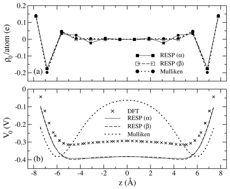
(a) Atomic partial charges determined from RESP (model α and β) and Mulliken population analysis for a (6,6) SWNT segment of 12 sections. (b) Corresponding electrostatic potential along the tube axis in comparison with results from DFT calculations.
DFT calculations are simply too expensive for obtaining RESP charges of even longer (l > 12) SWNTs. For this reason, we developed a 3-parameter RESP model (model β) with empirical expressions for atomic partial charges of ideal structures. Despite the small number of parameters, the resulting charges and quadrupole moments of model β are found to be within the same level of accuracy as those of model α (see Table 2 and 3). The ESP profiles in Fig. 2(b) also show good agreement between the two models. For SWNTs with 5 to 12 sections, charges on H and C1 atoms show little deviation from their mean values, which we assume still to be true for even longer SWNT segments. Their partial charges for ideal structures are determined to be (0.1353 ± 0.0008)e for each H atom and (−0.174 ± 0.002)e for each C1 atom. The charge on C2 atoms exhibits an exponential dependence on the number of sections l, which can be fitted to a function of the form qc2(l) = α1 − α2 e−a3 l with α1 = (0.044 ± 0.001) e, α2 = (5 ± 4) e, and α3 = 1.0 ± 0.2. The charge for other carbon atoms, e.g., C3, C4, … (see Fig. 1), can be calculated readily from the charge neutrality condition. Using the stated empirical expressions, one can determine rather easily partial charges for an ideal (6,6) SWNT with more than twelve sections.
Electronic Properties
In the following, we consider the length dependence of the HOMO/LUMO gaps and the dielectric behavior of finite-length armchair SWNTs, and discuss the correlation between these electronic properties. Unless specified otherwise, we refer to properties calculated for the ideal SWNT geometry.
Band Gap Oscillation
The band gaps of nanotubes with ideal geometry computed with B3LYP and TB methods are shown in Fig. 3 as a function of l. The two band gap curves exhibit similar oscillation patterns, and clearly fall into three classes characterized through lengths l = 3s + w, with s being an integer and w = 0, ±1 specifying the classes. The TB band gap is systematically lower than the B3LYP band gap by ~ 1 eV at short lengths, because TB parameters used here were derived by fitting the band structure of graphene to pure DFT results,28 with the latter known for underestimating the band gap.16 On the other hand, as a hybrid DFT variant, the B3LYP method17 should improve the accuracy of the band gap by using a mixture of the Hartree-Fock exchange and the DFT exchange-correlation functional. As the TB band gap minima always occur at l = 3s − 1, the B3LYP band gap minima switch from l = 3s − 1 to l = 3s when s > 2. This difference is caused by the neglect of the curvature effect in our TB model, which plays less of a role for SWNTs with larger radii, e.g., for a (10,10) SWNT.12,16
Figure 3.
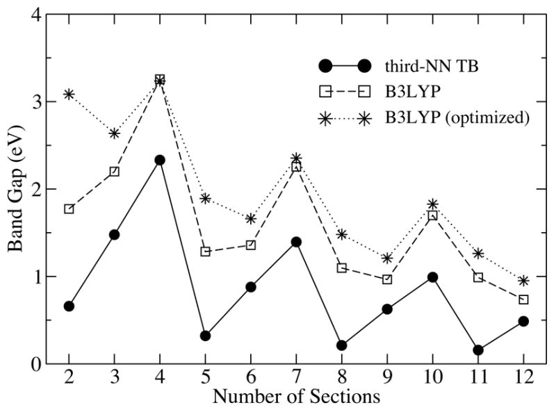
Band gap variation of a (6,6) nanotube as a function of tube length computed by both TB (circles) and B3LYP (squares) methods for the ideal nanotube geometry. Band gaps for the energy optimized geometry from the B3LYP calculation are also shown (stars).
The HOMO and LUMO obtained from the B3LYP and TB methods are also analyzed, and the nodal structures are found to be almost identical except for l = 3s + 1. Without considering the curvature, HOMO (LUMO) and the next HOMO (LUMO) at l = 3s + 1 are very close in energy, and the inclusion of curvature causes their relative positions in the energy spectrum to switch. Accordingly, HOMO and LUMO predicted by the TB method become the next HOMO and the next LUMO in the B3LYP method.
Upon structure optimization, the energy levels shift, including those of the HOMO and LUMO. The B3LYP band gaps for optimized (6,6) SWNTs are found to be noticeably larger than those for an ideal geometry at l = 3s and l = 3s− 1 (see Fig. 3). At l = 3s+1, the band gap is almost unchanged, though a closer examination reveals that the separation between the next HOMO and next LUMO increases by about a few hundred meV after optimization.
Dielectric Response
In the following, we discuss the dielectric screening parallel and perpendicular to the tube axis in SWNTs.
Axial dielectric screening
The dielectric screening ability of SWNTs can be characterized by defining the dielectric constant ε = Vext/Vtot, where Vext and Vtot are the external and total electrostatic potential on the SWNT surface. Shown in Fig. 4 is the total electrostatic potential on a 12-section (6,6) SWNT in response to an external electric field E = 25.7mV/Å applied along the tube axis. The B3LYP and third-NN TB potential profiles agree generally, except at the edges, where a steeper potential variation between carbon and hydrogen atoms is observed in case of the TB results. This can be explained by the fact that the TB model employs an all π-electron approximation and neglects the polarization between hydrogen and carbon atoms, which effectively screens out the external potential at the edge. The axial dielectric constants, ε||, are extracted from the middle region of the potential profiles, i.e., the region more than two sections away from the edge. We found and .
Figure 4.
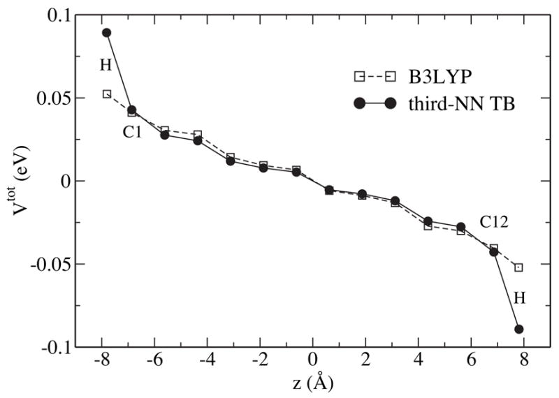
Total electrostatic potential on a (6,6) SWNT segment with 12 sections in a uniform axial field of strength E = 25.7mV/Å.
The corresponding dielectric constants of short SWNTs of 6 – 12 sections are plotted in Fig. 5. Both TB and B3LYP methods show very similar patterns of ε|| as a function of l, except that assumes slightly higher values (~ 10%) than . This can be partly attributed to the fact that the pure DFT method, used in the TB parameterization, usually overestimates the dielectric constant. Moreover, as mentioned earlier, neglecting the nonzero overlap integrals increases by ~ 5%. The σ electrons, which are not included in the TB method, also influence the overall screening ability.
Figure 5.
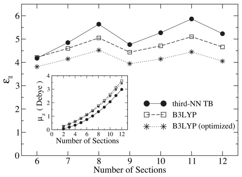
Parallel dielectric constant, ε||, for (6,6) SWNT segments with 6–12 sections. Inset: Induced dipole moment under a parallel field of E = 25.7mV/Å as a function of SWNT length.
The inset of Fig. 5 shows the induced axial dipole moment, μz, of the SWNT under a parallel electric field as calculated by the TB and B3LYP methods. Both curves exhibit a quadratic increase of μz with the tube length, though the B3LYP values are larger than the TB values, since the hydrogen termination causes nanotubes in the B3LYP description to be effectively longer than those in the TB description. The difference in the effective length yielded from a numerical fit is ΔL ≈ 1.9 Å, which is the same as the extra tube length due to the H atoms at the tube edges, i.e., 2dCH sin(π/3). Therefore, hydrogen atoms not only stabilize the system by saturating the dangling bonds, but also extend the range of dielectric screening.
It is interesting to notice a few important features of the length dependence of ε|| in Fig. 5. First, there is no direct correspondence between and the inverse of the band gap ( in Fig. 6). This can be understood from the special symmetry of armchair SWNTs. Under a uniform field along the axis, electronic transitions only occur between states with the same angular momentum and same parity about the vertical mirror reflection σv, which excludes the HOMO-LUMO transition.12 The lowest symmetry-allowed transition energy ΔE|| is plotted in Fig. 6, and one immediately recognizes a strong correlation between and as a function of l. Second, unlike in the case of the band gap, curvature effects do not influence the oscillation pattern because curvature only shifts the Fermi point along the axial direction12,31 and does not affect the relative energy separation between transition-allowed states near the Fermi point. Third, structure optimization is found to lower the screening capability, which is not surprising since structure optimization always tends to increase the energy separation between occupied states and unoccupied states, resulting in larger ΔE|| and smaller ε|| values.
Figure 6.
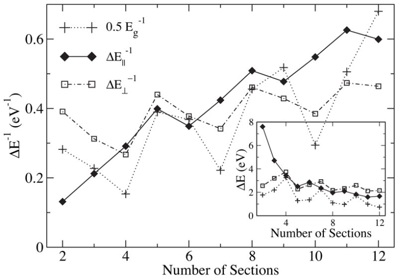
Inverse of the lowest transition energies ΔE|| and ΔE⊥ (see text) as a function of tube length computed at the B3LYP/6-31G* level of theory. The inverse of the HOMO/LUMO gap, Eg, is shown for comparison. is scaled by 0.5 to fit into the figure. Transition energies and the HOMO/LUMO gap are shown in the inset.
Perpendicular dielectric screening
For fields perpendicular to the tube axis, the quantity characterizing the dielectric screening, ε⊥, measures ~ 5 for infinitely long SWNTs.32 At finite length, the value of ε⊥ oscillates with l. Shown in Fig. 7 is ε⊥ calculated by means of TB and B3LYP methods for l = 4 to 12. The oscillation patterns for both methods are similar, except that at l = 3s is larger than that at l = 3s + 1, while behaves in the opposite manner. In addition, is found to be systematically higher than , which is related to the neglect of contributions from σ-electrons in the TB model. The inset in Fig. 7 shows for SWNT segments up to 30 sections long. One can discern that the behavior of clearly splits into two tails: l = 3s or 3s + 1, and l = 3s − 1. of the first tail converges monotonically to the limiting value , while of the second tail converges to in an oscillating fashion and more quickly. We plot in Fig. 6 the inverse of the lowest transition energy, , under a perpendicular field. One can recognize a close match of its length dependence to that of . Similar to the case of the parallel dielectric response, structure optimization tends to systematically lower the screening capability in the perpendicular direction.
Figure 7.
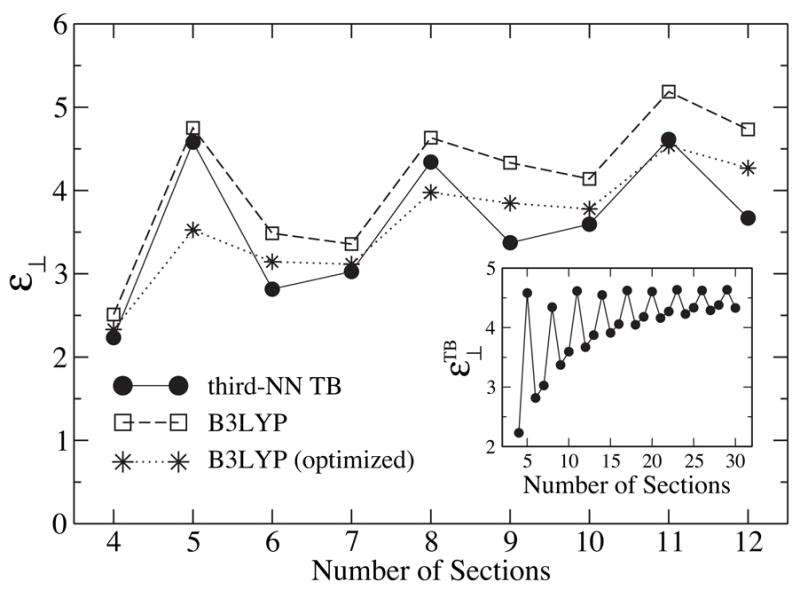
Dielectric constant ε⊥ for (6,6) SWNT segments with 4–12 sections. Inset: Third-NN TB dielectric constant, , for SWNTs with up to 30 sections.
Interaction Between a Water Molecule and a SWNT Segment
For applications of CNTs as biosensors and molecular channels, it is essential to understand their interaction with biomolecules in an aqueous environment. The interaction includes the short-range van der Waals interaction, UL–J, the Coulomb interactions arising from the atomic partial charges, U0, and interactions with charges induced on the SWNT, Uind. For an illustration, we present the potential energy between a water molecule and an ideal 12-section SWNT segment. As shown in Fig. 8, the oxygen atom of a water molecule is moved along the tube axis z, and the hydrogen atoms are symmetrically placed giving the water molecule a fixed orientation. Geometry and atomic partial charges of the water molecule are assumed to be those of the TIP3P model,33 i.e., dOH = 0.9572 Å, θHOH = 104.52°, and q(O) = −2 q(H) = −0.834 e. Amber 94 force field parameters23 are used for the C-O Lennard-Jones potential, i.e., UL–J (r) = 4.0 εco [(sco/r)12 − (sco/r)6], where εco = 0.1143 kcal/mol and sco = 3.2752 Å.
Figure 8.
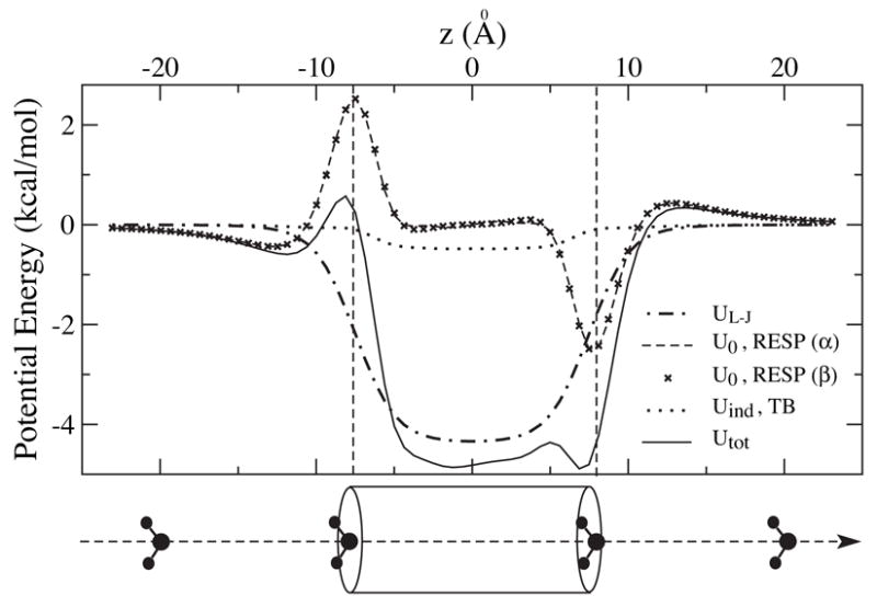
Potential energy profiles for an ideal 12-section (6,6) SWNT interacting with a water molecule of fixed orientation at various positions along the tube axis.
As one can see in Fig. 8, UL–J is symmetric with a simple potential well of −4.34 kcal/mol in the middle of the tube. In contrast, U0 is anti-symmetric. The potential profiles from the standard RESP fitting (model α) and the 3-parameter RESP fitting (model β) are nearly identical. The edge dipoles of the SWNT strongly affect the energetics of water entering the tube. At the left side, a water molecule encounters a shallow potential well of −0.44 kcal/mol followed by a high potential barrier of 2.97 kcal/mol. It experiences a small barrier and a deep well when entering the SWNT from the right side in the given, fixed orientation. In the middle of the tube, the potential is nearly vanishing. Uind has a similar shape as UL–J, but is an order of magnitude smaller.
In summing up the above three contributions, the total potential, Utot, exhibits several characteristic features. Its major contribution stems from UL–J, but at the edges, the shape is dominated by U0. The existence of edge dipoles also creates bumps in Utot, which may slow down the transport of water molecules through SWNTs. Compared to the bare UL–J, the potential well of Utot is lowered by 0.55 kcal/mol mainly due to Uind. A previous study34 indicated that water flow is primarily limited by the barriers at the entry and exit of the nanotube, so it becomes more important to improve the potential profile near the tube edges by including U0 in our model.
Although Uind is small compared to other contributions in Fig. 8, it becomes significant for ions and charged molecules. For instance, the interaction energy between a point charge of +e at the tube center and its image charges on the same SWNT segment as considered above is found to be 15.2 kcal/mol.12 It is also interesting to consider the effect of external electric fields on the molecules inside SWNTs.7,35 Neglecting the screening ability of SWNTs should exaggerate the impact of external fields. Consequently, results obtained under a field of 0.15 V/nm7 or an even stronger field of 1 V/nm35 without considering the polarization effects of the SWNT may have to be reexamined.
Conclusion
In this study, we developed an empirical finite-length armchair SWNT model, in which atomic partial charges are derived from DFT calculations, and the dielectric response is described by a TB model, which shows good agreement with DFT results for key dielectric properties. Our model can characterize SWNT-based molecular channels and can also account for the effect of external electric fields. As an illustration, the interaction between a single water molecule and a short SWNT segment has been closely examined. It was found that the atomic partial charges on the tube edges greatly contribute to the total interaction energy, while the polarization of the SWNT lowers the electrostatic energy weakly, but significantly, once the water molecule moves inside the nanotube. The properties described should influence water molecules and polar solutes entering, moving through, and reorienting inside SWNTs.
Acknowledgments
The authors thank Ioan Kosztin, Slava Rotkin, Michael Strano, Peter Albrecht, and Markus Dittrich for valuable discussions. L.D. and L.Y. were partly supported by the Institute for Theoretical Sciences, a joint institute of Notre Dame University and Argonne National Laboratory, funded through DOE contract W-31-109-ENG-38. This work was funded by NIH grant P41-RR05969, by NSF grants MCB 02-34938, CCR 02-10843, CCR 01-21616, and by the ARMY DURINT contract SIT527826-08. Computer time was provided through grant MCA93S028 from the National Resource Allocations Committee.
References
- 1.Hummer G, Rasaiah JC, Noworyta JP. Nature. 2001;414:188–190. doi: 10.1038/35102535. [DOI] [PubMed] [Google Scholar]
- 2.Noon WH, Ausman KD, Smalley RE, Ma J. Chem Phys Lett. 2002;355:445–448. [Google Scholar]
- 3.Mashl RJ, Joseph S, Aluru NR, Jakobsson E. Nano Letters. 2003;3:589–592. [Google Scholar]
- 4.Zhu F, Schulten K. Biophys J. 2003;85:236–244. doi: 10.1016/S0006-3495(03)74469-5. [DOI] [PMC free article] [PubMed] [Google Scholar]
- 5.Dellago C, Naor MM, Hummer G. Phys Rev Lett. 2003;90:105902. doi: 10.1103/PhysRevLett.90.105902. [DOI] [PubMed] [Google Scholar]
- 6.Mann DJ, Halls MD. Phys Rev Lett. 2003;90:195503. doi: 10.1103/PhysRevLett.90.195503. [DOI] [PubMed] [Google Scholar]
- 7.Joseph S, Mashl RJ, Jakobsson E, Aluru NR. Nano Letters. 2003;3:1399–1403. [Google Scholar]
- 8.Wei C, Srivastava D. Phys Rev Lett. 2003;91:235901. doi: 10.1103/PhysRevLett.91.235901. [DOI] [PubMed] [Google Scholar]
- 9.Yeh IC, Hummer G. Proc Natl Acad Sci USA. 2004;101:12177–12182. doi: 10.1073/pnas.0402699101. [DOI] [PMC free article] [PubMed] [Google Scholar]
- 10.Kolesnikov AI, Zanotti JM, Loong CK, Thiyagarajan P, Moravsky AP, Loutfy RO, Burnham CJ. Phys Rev Lett. 2004;93:035503. doi: 10.1103/PhysRevLett.93.035503. [DOI] [PubMed] [Google Scholar]
- 11.Hou S, Shen Z, Zhao X, Xue Z. Chem Phys Lett. 2003;373:308–313. [Google Scholar]
- 12.Lu D, Li Y, Rotkin SV, Ravaioli U, Schulten K. Nano Lett. 2004;4:2383–2387. [Google Scholar]
- 13.Halls MD, Schlegel HB. J Phys Chem B. 2002;106:1921–1925. [Google Scholar]
- 14.Chen J, Hamon MA, Hu H, Chen Y, Rao AM, Eklund PC, Haddon RC. Science. 1998;282:95–98. doi: 10.1126/science.282.5386.95. [DOI] [PubMed] [Google Scholar]
- 15.Saito R, Dresselhaus G, Dresselhaus MS. Physical Properties of Carbon Nanotubes. Imperial College Press; London: 1998. [Google Scholar]
- 16.Rochefort A, Salahub DR, Avouris P. J Phys Chem B. 1999;103:641–646. [Google Scholar]
- 17.Becke AD. J Chem Phys. 1993;98:5648–5652. [Google Scholar]
- 18.Frisch MJ, et al. Gaussian 03, Revision C.01. Gaussian Inc; Wallingford, CT: 2004. [Google Scholar]
- 19.Millefiori S, Alparone A. J Mol Struct. 1998;422:179–190. [Google Scholar]
- 20.Woon DE, Dunning TH., Jr J Chem Phys. 1993;98:1358–1371. [Google Scholar]
- 21.Huzinaga S, Andzelm J, Klobukowski M, Radzio-Andzelm E, Sasaki Y, Tatewaki H. Gaussian Basis Sets for Molecular Calculations. Elsevier; Amsterdam: 1984. [Google Scholar]
- 22.Matsuo Y, Tahara K, Nakamura E. Org Lett. 2003;5:3181–3184. doi: 10.1021/ol0349514. [DOI] [PubMed] [Google Scholar]
- 23.Cornell WD, Cieplak P, Bayly CI, Gould IR, Merz KM, Jr, Ferguson DM, Spellmeyer DC, Fox T, Caldwell JW, Kollman PA. J Am Chem Soc. 1995;117:5179–5197. [Google Scholar]
- 24.MacKerell AD, Jr, et al. J Phys Chem B. 1998;102:3586–3616. doi: 10.1021/jp973084f. [DOI] [PubMed] [Google Scholar]
- 25.Lindahl E, Hess B, van der Spoel D. J Mol Model. 2001;7:306–317. [Google Scholar]
- 26.Bayly CI, Cieplak P, Cornell WD, Kollman PA. J Phys Chem. 1993;97:10269–10280. [Google Scholar]
- 27.Cornell WD, Cieplak P, Bayly CI, Kollman PA. J Am Chem Soc. 1993;115:9620–9631. [Google Scholar]
- 28.Reich S, Maultzsch J, Thomsen C, Ordejón P. Phys Rev B. 2002;66:035412. doi: 10.1103/PhysRevLett.92.075501. [DOI] [PubMed] [Google Scholar]
- 29.Esfarjani K, Kawazoe Y. J Phys: Condens Matter. 1998;10:8257–8267. [Google Scholar]
- 30.Sutton AP. Electronic Structure of Materials. Oxford University Press; New York: 1996. [Google Scholar]
- 31.Kleiner A, Eggert S. Phys Rev B. 2001;64:113402. [Google Scholar]
- 32.Li Y, Rotkin SV, Ravaioli U. Nano Letters. 2003;3:183–187. [Google Scholar]
- 33.Jorgensen WL, Chandrasekhar J, Madura JD, Impey RW, Klein ML. J Chem Phys. 1983;79:926–935. [Google Scholar]
- 34.Kalra A, Garde S, Hummer G. Proc Natl Acad Sci USA. 2003;100:10175–10180. doi: 10.1073/pnas.1633354100. [DOI] [PMC free article] [PubMed] [Google Scholar]
- 35.Vaitheeswaran S, Rasaiah JC, Hummer G. J Chem Phys. 2004;121:7955–7965. doi: 10.1063/1.1796271. [DOI] [PubMed] [Google Scholar]


