

Abstract
Sustained release of proteins from aligned polymeric fibers holds great potential in tissue-engineering applications. These protein–polymer composite fibers possess high surface-area-to-volume ratios for cell attachment, and can provide biochemical and topographic cues to enhance tissue regeneration. Aligned biodegradable polymeric fibers that encapsulate human glial cell-derived neurotrophic factor (GDNF, 0.13 wt%) were fabricated via electrospinning a copolymer of caprolactone and ethyl ethylene phosphate (PCLEEP) with GDNF. The protein was randomly dispersed throughout the polymer matrix in aggregate form, and released in a sustained manner for up to two months. The efficacy of these composite fibers was tested in a rat model for peripheral nerve-injury treatment. Rats were divided into four groups, receiving either empty PCLEEP tubes (control); tubes with plain PCLEEP electrospun fibers aligned longitudinally (EF-L) or circumferentially (EF-C); or tubes with aligned GDNF-PCLEEP fibers (EF-L-GDNF). After three months, bridging of a 15 mm critical defect gap by the regenerated nerve was observed in all the rats that received nerve conduits with electrospun fibers, as opposed to 50% in the control group. Electrophysiological recovery was seen in 20%, 33%, and 44% of the rats in the EF-C, EF-L, and EF-L-GDNF groups respectively, whilst none was observed in the controls. This study has demonstrated that, without further modification, plain electrospun fibers can help in peripheral nerve regeneration; however, the synergistic effect of an encapsulated growth factor facilitated a more significant recovery. This study also demonstrated the novel use of electrospinning to incorporate biochemical and topographical cues into a single implant for in vivo tissue-engineering applications.
1. Introduction
Electrospun fibrous scaffolds have found increasing popularity in the field of tissue engineering over the past few years. These scaffolds have been applied to various areas of tissue engineering, including cardiovascular tissue engineering,[1–3] musculoskeletal tissue engineering,[4–6] neural tissue engineering,[7] and stem cell engineering.[8–10] The popularity of electrospun scaffolds partially stems from their high surface-area-to-volume ratio available for cell attachment and also from the possibility of mimicking the extracellular matrix (ECM) architecture, thereby enhancing tissue regeneration.
A possible improvement to the electrospun scaffold system is to include biochemical cues by encapsulating proteins into the fibers to form a protein–polymer composite system.[11] These composite fibers will not only possess a large network of interconnected pores that is conducive to tissue ingrowth, but also a high surface area to provide local and sustained delivery of biochemical signals to the site of injury. To evaluate the potential of such protein–polymer composite fibers as a tissue-engineering platform, aligned electrospun protein-encapsulated fibers were investigated for the treatment of peripheral nerve injury.
Peripheral nerve regeneration and functional recovery is often disappointing over long-lesion gaps despite surgical interventions and entubulation of the injured nerve. By far, the most common method of treatment is the use of autografts for long-lesion gaps. However, drawbacks, such as the requirement of a second surgery and the lack of available donor nerves,[12–14] fuel the continuing search for better alternatives. The use of empty synthetic nerve conduits has been one of the popular choices. These synthetic tubes, however, are only successful in bridging short nerve gaps (e.g., ≤10 mm) in the rat model.[13,15–18] In addition, there appears to be a species-dependent critical defect gap size, for example, 15 mm in rats, beyond which the regeneration of injured nerves seldom occurs in these empty synthetic nerve guides.[12,17,19]
The lack of nerve regeneration across large-lesion gaps may be partially due to the inadequate formation of the extracellular matrix during the initial phase of recovery.[17] It can also be the lack of neurotrophic factors from the distal nerve stump to provide a conducive microenvironment for regeneration.[12,13] As a result, different approaches have been taken to enhance nerve regeneration, such as prefilling nerve conduits with ECM proteins;[17,18] introducing contact guidance,[14–18,20–23] and delivering neurotrophic factors to the site of injury via microspheres for controlled release[19,24] or via cells.[23–29]
Human glial cell-derived neurotrophic factor (GDNF) has potent survival effects on motor neurons both in vitro and in vivo.[30,31] During chronic injuries to the adult rat sciatic nerve, a rapid and dramatic up-regulation of GDNF messenger RNA (mRNA) expression in Schwann cells is observed.[24,32] GDNF mRNA expression is also upregulated in various human neuropathies and in traumatized human nerves.[32] Hoke et al. demonstrated that GDNF promotes the myelination of nerve fibers and the proliferation of Schwann cells in vitro.[32]
In this study, nerve conduits were fabricated to comprise the biodegradable copolymer poly(ε-caprolactone-co-ethyl ethylene phosphate) (PCLEEP) and aligned GDNF-PCLEEP electrospun fibers. The inclusion of aligned protein–polymer composite fibers effectively combines biochemical and topographical cues for enhanced sciatic nerve regeneration across a 15 mm critical defect in rats. The significance of the topographical cues provided by the aligned electrospun fibers in enhancing sciatic nerve regeneration is also addressed.
2. Results
Figure 1 shows the synthesis of PCLEEP and a schematic of the nerve guide fabrication process.
Figure 1.
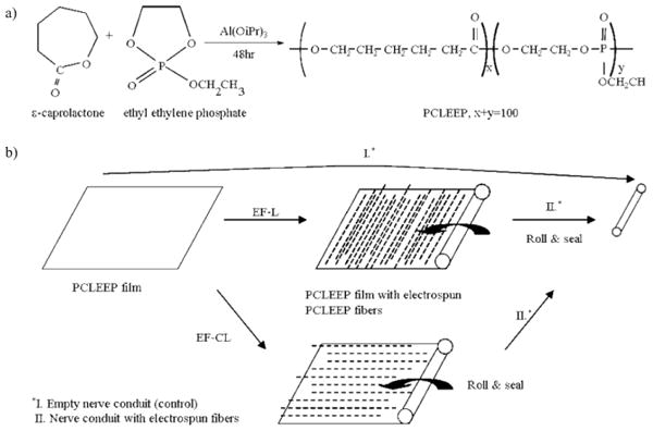
a) Synthesis of PCLEEP. b) Fabrication of nerve conduits. iPr: isopropyl.
2.1. In Vitro Protein Release Kinetics and Protein Distribution
Figure 2a shows the in vitro release profile of encapsulated GDNF from GDNF-PCLEEP electrospun fibers. After an initial burst release of about 30%, the remaining protein was released in a fairly sustained manner for almost two months before leveling off. The cumulative amount of GDNF released per mass of composite fibers is also shown in Figure 2a. With ca. 3.5 mg of GDNF-PCLEEP composite fibers in each nerve guide, the total amount of GDNF released per nerve guide after three months in vitro was ca. 17.7 ng. As shown in Figure 2b, the proteins were distributed uniformly throughout the polymer matrix in aggregates.
Figure 2.
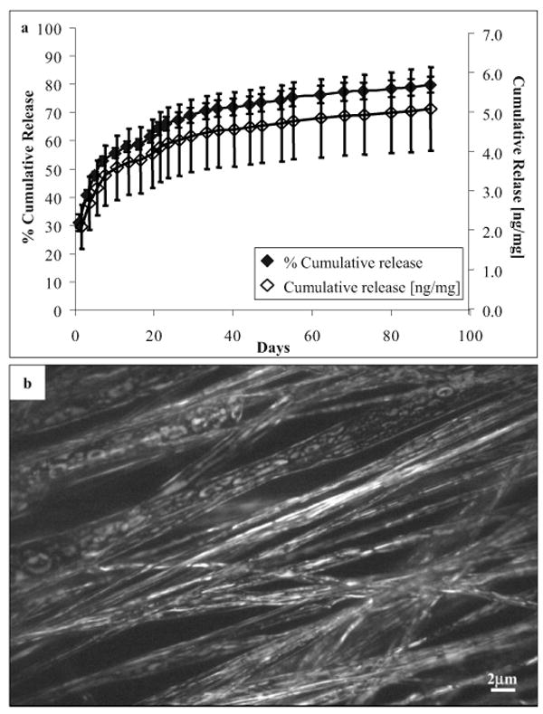
a) In vitro cumulative release profile of GDNF from aligned electrospun GDNF-PCLEEP composite fibers incubated at 37 °C under static conditions for three months. n = 4, mean ± standard error of the mean (SEM). b) Fluorescent image of protein distribution throughout GDNF-PCLEEP electrospun fibers.
2.2. Structure and Appearance of Nerve Guide Conduits
Figure 3a and b shows the cross sections and the inner surfaces of nerve conduits with longitudinally and circumferentially aligned electrospun fibers, respectively. The average inner diameter and wall thickness of the nerve guides were (1.5 ± 0.2) mm and (83.2 ± 2.9) μm, respectively. Figure 3c shows the alignment of the electrospun fibers on the inner surface of the nerve guides. The diameters of plain and GDNF-encapsulated PCLEEP fibers were (5.08 ± 0.05) mm and (3.96 ± 0.14) mm respectively. The inner surface of the empty control tube was generally smooth, as shown in Figure 3d.
Figure 3.
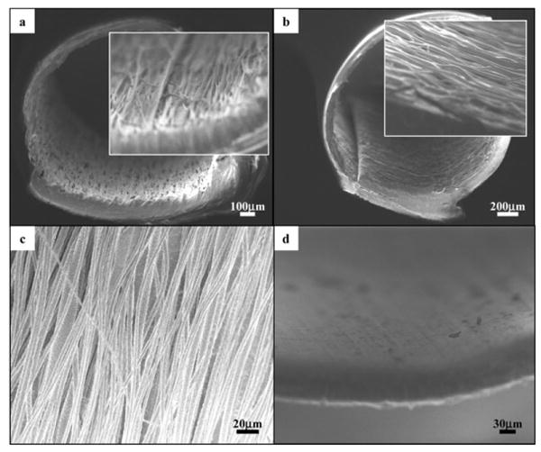
Cross-sectional views of nerve conduits with aligned electrospun fibers, a) EF-L and b) EF-C. Insets: higher-magnification views of the cross sections. c) Aligned PCLEEP fibers in nerve guide conduits, GDNF-encapsulated fiber diameter, φ=(3.96 ±0.14) μm and plain PCLEEP fiber φ= (5.08 ± 0.05) μm. d) Inner surface of an empty nerve guide conduit.
2.3. Morphological Evaluation
Light images of the cross-sections of the regenerated sciatic nerve are shown in Figure 4. All rats that received nerve guides with electrospun fibers (with or without GDNF) had regenerated sciatic nerve at 15 mm from the proximal end, as opposed to only 3 out of 6 in the group with empty nerve guides. Only 4 out of 6 rats in this control (empty nerve guide) group had regenerated sciatic nerve at 8–10 mm from the proximal end, out of which only 2 rats had myelinated axons at the same location. The results are summarized in Table 1.
Figure 4.
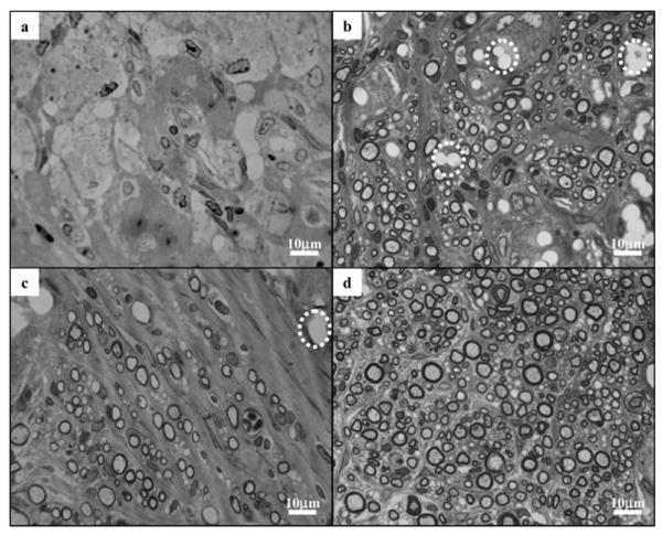
Light images of the cross-sections of regenerated sciatic nerves, 8–10 mm from the proximal end of nerve conduits in a) control; b) EF-L; c) EF-C; and d) EF-L-GDNF groups. Dashed circle: voids left over by PCLEEP electrospun fibers.
Table 1.
Total number of rats in each experimental group and the extent of sciatic nerve regeneration.
| Total no. of rats | Rats with regenerated sciatic nerve at 8–10 mm from proximal end | Rats with regenerated sciatic nerve at 15 mm from proximal end | Rats with myelinated axons at 8–10 mm from proximal end | Rats showing functional recovery | |
|---|---|---|---|---|---|
| Empty nerve guide | 6 | 4 | 3 | 2 | 0 |
| EF-C | 10 | 10 | 10 | 10 | 2 |
| EF-L | 9 | 9 | 9 | 9 | 3 |
| EF-L-GDNF | 9 | 9 | 9 | 9 | 4 |
Empty spaces taking the shape of fiber bundles, as identified by the dashed circles in Figure 4b, were observed in the nerve cross-sections from the EF-L group. The empty spaces are likely to be bundles of electrospun fibers that remained at the site of injury but dissolved during histology sample processing. Similar voids were observed in the nerve cross sections from the EF-C group, as indicated in Figure 4c. Protein–polymer composite fibers, however, were not found in any of the sciatic nerves from the EF-L-GDNF group.
The total number of myelinated axons, Mtot, and the nerve cross-sectional area, Atot, for each experimental group are shown in Figures 5a and 5b; respectively. With the inclusion of electrospun fibers, either longitudinally or circumferentially aligned but without GDNF, Mtot and Atot were significantly higher compared to the empty conduits. There is, however, no significant difference between the two different orientations of the aligned fibers. The introduction of exogenous growth factor significantly improved nerve regeneration. Figure 5c shows the G ratio of the experimental groups. In the case of the controls, the G ratio was computed based on the 2 animals that had myelinated axons at 8–10 mm from the proximal end of the nerve guide. No significant difference in G ratio was observed between the experimental groups.
Figure 5.
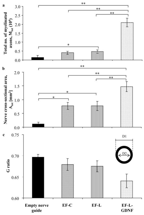
a) Total number of myelinated axons, Mtot at 8–10 mm from the proximal end of each regenerated sciatic nerve, *p < 0.05, **p < 0.01. b) Cross-sectional area of regenerated nerve Atot at 8–10 mm from proximal end, *p < 0.05 and **p < 0.01. c) G ratio, defined as the ratio of the diameter of the axon to the diameter of the entire myelinated fiber (D2/D1).
Typical transmission electron microscopy (TEM) images of the cross-sections of the regenerated sciatic nerves are shown in Figure 6. The regenerated nerves in the control group consisted mainly of fibrous tissues, with little or no myelinated axons observed. On the contrary, large numbers of myelinated axons were found in other experimental groups. Figure 6b illustrates the tendency of myelinated axons regenerating in close proximity to the electrospun fibers.
Figure 6.
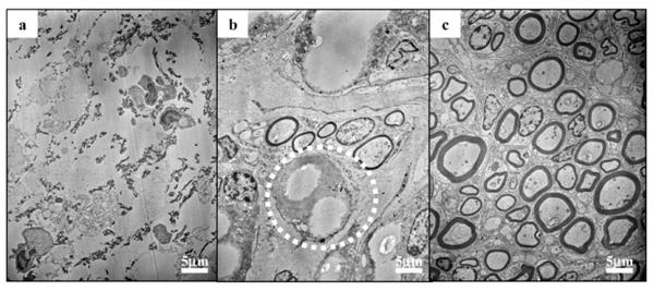
TEM images of cross sections of regenerated sciatic nerve, 8–10 mm from the proximal end of nerve conduits. a) In the control group, showing the absence of myelinated axons and the presence of fibrous tissues. b) In the EF-L group, showing the tendency of myelinated axons regenerating in close proximity to PCLEEP fibers (circled). c) In the EF-L-GDNF group, demonstrating the presence of a large number of myelinated axons.
2.4. Immunofluorescent Staining and Histological Evaluation
Figure 7a shows the fluorescent image for ED1 immunostaining of the nerve cross section. For all experimental groups, activated macrophages were found mostly along the periphery of the regenerated nerve, which was in close contact with the nerve conduit. The haematoxylin & eosin (H&E) staining of the nerve cross sections from experimental groups that received nerve guides with plain PCLEEP fibers is shown in Figure 7b. The image reveals the absence of an acute immune response in close proximity to the fibers (identified by dashed circles), indicating the noninflammatory nature of the PCLEEP fibers.
Figure 7.
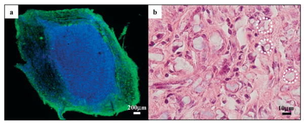
a) Immunofluorescent image of the cross section of a regenerated sciatic nerve 5–8 mm from the proximal end. Activated macrophages are found mostly along the periphery of the sciatic nerve. Green: ED1; blue: DAPI. b) Light image of the cross section of a regenerated sciatic nerve from EF-L, 5–8 mm from the proximal end, under H&E staining. No acute immune response was observed. Dashed circles: PCLEEP electrospun fibers.
2.5. Electrophysiological Assay—Evoked Motor Responses
Evoked motor responses at one and two months post-implantation revealed no recovery in any of the rats. However, electrophysiological recovery was observed three months post-implantation. The inclusion of GDNF-PCLEEP composite fibers led to partial functional recovery in four out of nine rats (Fig. 8a). Although not statistically significant, the inclusion of plain PCLEEP fibers also resulted in functional recovery in a portion of rats, as compared to none in the control group. Two out of ten rats and three out of nine rats in the EF-C and EF-L groups, respectively, showed electrophysiological recovery.
Figure 8.
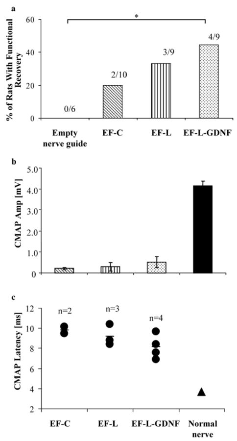
a) Percentage of rats per group that showed functional recovery, *p < 0.1, Fisher–Irwin test. b) CMAP amplitude. c) CMAP latency. EF-C: n = 2, EF-L: n = 3, EF-L-GDNF: n = 4.
Figure 8b and c illustrates the amplitudes of the CMAP and their corresponding latency, respectively. The amplitude and the latency of the CMAP of the animals that received GDNF-encapsulated nerve guides appeared to be better than those receiving nerve guides with plain electrospun fibers, although the results are not statistically significant because of the small number of animals that showed functional recovery. The values of the amplitude and latency remained inferior to a normal nerve.
3. Discussion
Poly(ε-caprolactone) is a biodegradable and biocompatible polymer that has been widely studied for medical device and drug delivery applications.[33,34] Its low degradation rate, however, makes it less optimal for some tissue-scaffolding applications. To enhance the biodegradability and flexibility of this polymer, addition of a phosphate group to the polymer backbone was carried out, forming PCLEEP. The choice of PCLEEP as the material for electrospinning protein–polymer composite fibers stems from our previous findings.[11] A sustained release of partially bioactive nerve growth factor (NGF) was obtained for a period of three months in vitro by encapsulating the protein in this biodegradable copolymer via electrospinning.[11]
Growth factors typically are labile. For example, the biologic half-lives of platelet-derived growth factor (PDGF), basic fibroblast growth factor (bFGF), and vascular endothelial growth factor (VEGF) are 2, 3, and 50 min, respectively, when intravenously administered.[35] As a result, the use of polymeric drug-delivery vehicles in the form of microspheres, nanospheres, and hydrogels to maintain a sustained localized delivery to the target site is attractive.[31,36,37] The choice of electrospun fibers as a drug-delivery vehicle has an added incentive in that they possess large surface areas and interconnected pores for tissue ingrowth. Although cells can be used as a source of growth factor, the isolation and expansion requirement may be a potential drawback of this approach for practical usage.[21,28,38]
The total volume of protein solution used in this study was restricted to 50 μL to minimize jet breakages during electrospinning. Being highly potent by nature, only minute amounts of growth factors (picograms to nanograms) are often required to elicit biological activity. While the exact concentration of GDNF required to elicit a biological response in the rat model using our experimental approach is unknown, the amount of GDNF loaded was the maximum given the experimental restrictions imposed by the electrospinning process.
The initial burst release observed for GDNF is mainly a result of the release of proteins localized on the surface of the fibers. Subsequent protein release occurs via diffusion.[11] Although in vitro protein release kinetics are expected to differ from those in vivo, the release profile nonetheless suggests the availability of bioactive GDNF to the regenerating neurons for at least one to two months. The formation of protein aggregates throughout the polymer matrix originates from the phase separation between the protein aqueous solution and the polymer solution.
As shown here, electrospinning not only enables one to produce fibers with diameters ranging from micrometers to sub-micrometer, but also allows the easy fabrication of protein–polymer composite fibers. Besides proteins; drugs[39–42] and even DNA[43] may be easily incorporated into the polymer fibers via electrospinning.
3.1. Morphological Analysis
With the inclusion of aligned electrospun fibers, the Mtot and Atot significantly increased. We have previously speculated that the contact guidance provided by the longitudinally aligned fibers, along with the increase in surface area available for cell attachment and growth, would enhance the nerve regeneration. The control group of circumferentially aligned fibers, EF-C, was an attempt to uncouple these two factors. As morphometric analysis revealed no significant differences, the conclusion leans towards a more adhesive surface rather than the effects of contact guidance.
The further significant improvement in nerve regeneration with the addition of exogenous GDNF demonstrates the effectiveness of the growth factor in enhancing nerve regeneration. The improved nerve regeneration in the presence of GDNF may also be attributed to a possible increase in macrophage invasion in response to the presence of the human protein during early stages of recovery. The macrophage invasion is manifested in the faster degradation of the electrospun fibers. Because macrophages have been found to release cytokines such as interleukin-1 (IL-1) that stimulate NGF production from cells like Schwann cells,[18] this may in turn add to the GDNF effect.
A normal rat sciatic nerve contains (7115 ± 413) myelinated nerve fibers.[44] Clearly, the regenerated sciatic nerve in the empty conduit group is far inferior to a normal nerve, even after three months of recovery. The number of axons in the groups that received plain electrospun fibers, aligned in either direction, is close to that of a normal sciatic nerve. In contrast, the value from the EF-L-GDNF group lies well above the normal. The larger than normal number of myelinated axons is not uncommon. It has been observed that the number of regenerated nerve fibers can be larger than the normal number, even after seven months of recovery.[12,45] Regenerating neurons can support multiple branching from the site of injury so as to maximize the possibility of each neuronal cell to reach its target organ.[27,45]
A G ratio of about 0.7 is ideal for nerve conduction,[25] and it hovers around 0.6–0.7 in normal uninjured nerves.[26] From Figure 5c, the G ratios of the groups that received electrospun fibers lie well within the range of the normal nerve. In general, a decreasing trend in the G ratio was observed in the presence of electrospun fibers and the introduction of GDNF, respectively, indicating an enhancement in maturation of the myelinated axons compared to an empty nerve conduit.
Both light and electron microscopy revealed the presence of plain PCLEEP fibers in the nerve guides at the time of sacrifice. However, no GDNF-PCLEEP composite fibers could be found in the EF-L-GDNF group. While the exact reason behind this observation is unclear, it appears that a more pronounced immune response towards the encapsulated and released human GDNF from the fibers, as manifested by activated macrophages found in the periphery of the regenerated nerve, has accelerated the degradation of the fibers, leading to complete degradation within three months.
3.2. Electrophysiological Assay—Evoked Motor Responses
The success in achieving electrophysiological recovery in a significant portion of animals highlights the efficacy of the electrospun protein–polymer composite fibers. This study also differs from many others in which the filaments included in the nerve guide were of diameters between 20 to 100 μm, much larger than the ones used in this study.[14,16,18] While many studies evaluated the state of nerve regeneration through morphological analyses,[14,16–18,20] we adopted a stringent electrophysiological assay to measure the muscle action potential at the most distal foot muscles after sciatic nerve stimulation. A functional assay is important because recovery is not always guaranteed even though nerve regeneration has occurred, because of possible failure of regenerating axons to reach the appropriate target.[21]
Whilst morphological analyses revealed significant differences in axonal regeneration and myelination between the EF-L-GDNF group and other experimental groups, the difference in functional recovery between the EF-L-GDNF and the EF-L and EF-C groups was less significant. This discrepancy may be due to the fact that the functional test was conducted in the most distal muscles in the rats, as opposed to the more proximal location (8–10 mm from the proximal end of the site of injury) where morphological evaluation was carried out. At only three months post-implantation, there might not have been sufficient time for complete regeneration of the sciatic nerve to occur. Perhaps functional evaluation at longer time points might show more significant differences between the experimental groups.
3.3. Contact Guidance versus Surface Area Effect
As with most other studies, this study started with the aim to introduce contact guidance to enhance nerve regeneration. The main difference, however, is that contact guidance was introduced along the walls instead of the center of the nerve guides. Because the presence of aligned filaments along the center of nerve guides have not been shown to effectively enhance functional recovery in sciatic nerve injuries,[14,16,18] inclusion of aligned fibers along the walls of the nerve guides was adopted. Such a design was also an attempt to overcome the problems of uneven distribution of fibers within the center of the nerve guide at low packing densities, and the hindrance of nerve regeneration at high packing densities, as experienced previously by Ngo et al.[18] The nature of the electrospinning process, along with the fact that electrospun fibers are at least an order of magnitude smaller in diameter than the filaments used in previous studies,[14,16,18] also made it easier to include electrospun fibers on the walls by directly electrospinning aligned fibers onto the nerve guides instead of stuffing the aligned fibers into the center of the nerve guides.
The inclusion of electrospun fibers not only introduces contact guidance, but also increases the total surface area available for cell ingrowth. Even though aligned fibers were electrospun onto the walls of the nerve guides, numerous aligned fibers were found to be incorporated into the cross sections of the regenerated sciatic nerves, particularly in the EF-L group (Figs. 4b,c and 7b). Myelinated axons were also found to grow in close proximity to the electrospun fibers (Fig. 6b). The detachment of the aligned fibers from the walls of the nerve guides is caused by the weak nonspecific bonding between the electrospun fibers and the nerve guides. Effectively, the electrospun fibers provided contact guidance to cells both in the center and along the walls of the nerve guides. However, the insignificant differences in the degree of nerve regeneration between the orientations of the aligned fibers seem to suggest that contact guidance may not play as prominent a role as hypothesized using the current design of the nerve guides. However, the possibility of contact guidance playing a significant role during the initial or early phase of nerve regeneration in our experimental approach cannot be eliminated. Through morphological analyses, Ceballos et al.[17] reported enhanced sciatic nerve regeneration in mice by using aligned collagen gel, as compared to random collagen gels, at 60 days post-implantation. The alignment and elongation of cells on micro-[46,47] and nanoscale topographies[48] are also often observed in in vitro cell cultures within a period of one week. A confirmation of such a hypothesis would require an evaluation of the state of nerve recovery at earlier time points.
4. Conclusions
Electrospun GDNF-PCLEEP composite fibers showed a sustained release of protein for up to two months in vitro. Evaluation of these aligned protein–polymer composite scaffolds as a potential tissue engineering platform was carried out by treatment for peripheral nerve injury. Morphological and functional assays showed enhanced nerve regeneration in the presence of the electrospun fibers. By using the design adopted in this study, the increase in surface area provided by the electrospun fibers for cellular ingrowth appears to be the more dominant factor in enhancing nerve regeneration, as compared to contact guidance at three months post-operation. This study confirms the hypothesis that biochemical cues provided by the exogenous GDNF can lead to improved tissue regeneration. On its own, an increase in surface area can help in tissue regeneration; however, the synergistic effect of the encapsulated protein promotes a more significant recovery. The potential of electrospun protein–polymer composite scaffolds as a tissue-engineering platform is clearly demonstrated. This study also served to show the use of electrospinning as a simple and feasible method to include biochemical and topographic cues into a single implant to enhance tissue regeneration.
5. Experimental
5.1. Poly(ε-caprolactone-co-ethyl ethylene phosphate)
The PCLEEP copolymer with 15 mol% ethyl ethylene phosphate (EEP) (weight-average molecular weight (Mw) 70 760 g mol−1, number-average molecular weight (Mn) 25 800 g mol−1) was synthesized according to a procedure described by Wen et al. [49]. The synthesis is illustrated in Figure 1a. Briefly, ε-caprolactone and EEP were copolymerized in an ampoule using Al(OiPr)3 as the initiator. After vacuum drying for 3 h, the ampoule was sealed and immersed in an oil bath at 100 °C for 48 h. The resulting polymer was dissolved in dichloromethane, washed with saturated NaCl solution three times, and then dried over Na2SO4. After quenching the solution into ether, the precipitated polymer was further purified by dissolving in acetone and quenching in distilled water.
5.2. Nerve Guide Conduit Fabrication
The fabrication process of the nerve conduits is highlighted in Figure 1b. A PCLEEP film was fabricated by subjecting 0.5 g of polymer to a uniaxial compression load of 8 × 10³ kg for 2 min at 65 °C. The film was then rolled and sealed with 8 wt% of PCLEEP-dichloromethane solution into a cylinder to serve as an empty PCLEEP nerve conduit for the control group.
Nerve conduits with PCLEEP fibers were fabricated by electrospinning aligned fibers directly onto the PCLEEP film. Based on previous experiments [11], 12 wt% of PCLEEP in dichloromethane was used as the electrospinning solution. The PCLEEP film was mounted on a grounded aluminum drum, 10 cm in diameter, rotating at 2200 rpm. The distance between the polymer solution and the film was set at 5–6 cm. The polymer solution was dispensed at a flow rate of 6 mL h−1 and an electrical voltage of 8 kV was applied to the solution.
GDNF-encapsulated PCLEEP fibers were fabricated by electrospinning a mixture of protein and polymer solution. The protein solution comprised 45 μL of GDNF (Amgen Inc, 5 mg mL−1) and 5 μL of 30 wt% of bovine serum albumin (BSA) (Sigma-Aldrich Corporation) in phosphate-buffered saline (PBS) (Gibco, Invitrogen Corporation), resulting in a GDNF theoretical loading level of 0.13 wt% in the polymer solution. The protein–polymer solution was vortexed to uniformly distribute the protein suspension throughout the polymer solution. The resulting solution required a dispense rate of 8 mL h−1 and 7.5 kV for electrospinning, while all other processing parameters were kept the same as those used for electrospinning plain PCLEEP fibers.
For each experimental group, one PCLEEP film and 1.0 mL of polymer solution were used for electrospinning. The final composite of film and fibers was then rolled and sealed with 8 wt% of PCLEEP-dichloromethane solution into tubes. The electrospun fibers were aligned either longitudinally (EF-L) or circumferentially (EF-C). The nerve conduits were sterilized by ultraviolet radiation in a laminar flow hood for 30 min prior to surgical implantation. The distance between the nerve guides and the ultraviolet lamp was set at approximately 30 cm.
5.3. Protein Distribution and in vitro Release Kinetics
To visualize the protein distribution throughout the fibers and to study the in vitro protein release kinetics, aligned protein-encapsulated fibers were fabricated by electrospinning 1.0 mL of polymer–protein solution directly onto the grounded rotating drum without a polymer film. Similar processing parameters as those highlighted above were used.
Each aligned protein-encapsulated fibrous mesh, weighing (50.7 ± 4.9) mg, was incubated in 3.0 mL of PBS with 0.01 wt% of sodium azide (Sigma) at 37 °C, under static conditions (n = 4). At various time points, 1.5 mL of supernatant was retrieved from the wells and replaced with the same volume of fresh PBS with sodium azide. The concentration of GDNF was determined by using the Duoset ELISA development kit (R&D Systems, Inc.), following the manufacturer's protocol with the exception that the standard curve was plotted based on various known concentrations of the GDNF from Amgen, Inc. The concentration of BSA was determined by using the MicroBCA Protein Assay Reagent kit (Pierce Biotechnology, Inc.) by assuming that the mass of GDNF released was negligible compared to BSA.
At the end of 3 months, the fibers were dissolved in 1.0 mL of dichloromethane and any residual GDNF was extracted into 1.0 mL of PBS for ELISA. The GDNF extraction efficiency was taken into account to compute for the actual residual GDNF in the fibers. The extraction efficiency was obtained by extracting known masses of GDNF (5 to 500 ng) loaded into a same concentration of PCLEEP solution (50.7 mg mL−1) together with ca. 1.6 mg of BSA. The mass of BSA loaded was obtained by assuming 100% loading efficiency during electrospinning and estimating the mass of residual BSA in the fibers based on the BSA release profile.
To visualize protein distribution, 0.2 wt% of fluorescein isothiocyanate BSA (FITC-BSA, Sigma) was added into the protein solution during electrospinning. The FITC-BSA doped fibers were then observed under the confocal fluorescent microscope (Perkin–Elmer UltraVIEW spinning disk confocal microscope).
5.4. Structure and Appearance of Nerve Guide Conduits
Nerve conduits with and without electrospun fibers were sputter-coated with chromium to a thickness of ca. 2.5–3 nm (Denton Vacuum, DV-502 A), prior to observation under the scanning electron microscope (Leo Field Emission SEM, Leo 1530) at a voltage of 1 kV. The average diameter of the electrospun fibers was determined by measuring at least 50 fibers using ImageJ 1.30v software (National Institutes of Health, USA)
5.5. In vivo Experiments: Surgical Procedure
Thirty-four adult female Sprague–Dawley rats approximately 3.5 months of age were divided into 4 groups, receiving either empty PCLEEP nerve conduits (control, n = 6), nerve conduits with plain electrospun PCLEEP fibers aligned longitudinally (EF-L, n = 9) or circumferentially (EF-C, n = 10), or nerve conduits with GDNF-PCLEEP electrospun fibers aligned longitudinally (EF-L-GDNF, n = 9). The rats were anesthetized under isoflurane (Atlantic Biomedical) delivered at a flow rate of 1 L min−1. The left sciatic nerve was then exposed through a posterior thigh muscle-splitting incision and 6 mm of the nerve was resected to obtain a 15 mm nerve lesion gap. The nerve conduit was sutured to the proximal stump with one 10–0 nylon monofilament (Surgical Specialties Corporation) suture stitch and the distal stump with one 6–0 silk filament (Ethicon Inc.) suture stitch. All nerve conduits, length 16 mm, were filled with 10 μL of PBS prior to implantation. To ensure secured position of the nerve conduit, Tissumend II synthetic absorbable tissue adhesive (Veterinary Products Laboratories) was applied to the ends and the external surface of the center of the nerve conduit. One suture stitch of 10–0 nylon monofilament and stainless steel wound clips (Autoclips) were then used to close the wound.
5.6. Electrophysiology—Motor-Evoked Responses
At 1, 2, and 3 months post-operation, electrophysiological recovery was assessed by motor-evoked responses. All animals were anesthetized under isoflurane (flow rate 1 L min−1) prior to the test. Compound motor action potential (CMAP) recordings in the foot muscles were recorded after stimulation of the sciatic nerve at the sciatic notch by needle electrodes as described before [29]. Both CMAP readings from the left and right sciatic nerves were recorded for each rat.
5.7. Morphological Evaluation
Three months post-implantation, all nerve conduits were retrieved, and nerve cross-sections at 8–10 mm from the proximal end were processed for toluidine blue staining and transmission electron microscopy (TEM). The samples were fixed in a solution of 4 wt% paraformaldehyde and 3 wt% glutaraldehyde for 2 days before being transferred into Sorrensons phosphate buffer (0.2 m) for further processing. The samples were mounted in embedding resin, sectioned on an Ultracut E microtome at 1 μm thickness and stained with 1% toluidine blue for light microscopy. TEM samples were cut on a Reichert Ultracut S microtome in 0.5–0.65 μm thickness, placed on 0.5% formvar coated meshes and stained with 5% uranyl acetate and 0.3% lead citrate.
Samples that were stained with toluidine blue were imaged on a Nikon Eclipse TE2000-U microscope. Morphometric analysis of nerve regeneration was carried out by image analysis using ImageJ. Quantification of the total number of myelinated axons per cross section of each regenerated nerve (Mtot) was carried out by photographing the entire cross section of each nerve at 400× magnification with consecutive non-overlapping shots. The total number of myelinated axons (Mn) and the total nerve area (An) in each photograph was computed for the number of myelinated axons per nerve area (number density, NDn = Mn/An). The final number density for each sciatic nerve cross-section (NDave) was then calculated as the average NDn of all the photos taken for each sciatic nerve. Mtot was calculated from the product of the total cross-sectional area (Atot) of the regenerated nerve (image obtained at 40×) and NDave. Evaluation of the G ratio, which is the ratio of axon diameter to the total diameter of the nerve fiber, was carried out by photographing randomly selected fields of each sciatic nerve cross-section at 1000× magnification. For each sample, at least 80 myelinated axons were measured.
For TEM analyses, nerve cross-sections were viewed under the Hitachi H600 electron microscope, using an accelerating voltage of 75 kV.
5.8. Histological Evaluation
Three months post-implantation, nerve cross-sections at 5–8 mm from the proximal end were retrieved and stored in 4% paraformaldehyde for immunofluorescent and haematoxylin & eosin (H&E) staining. The samples were transferred into 15% and then 30% sucrose solutions after 24 and 48 h, respectively. All samples were stored at 4 °C.
For macrophage staining, the sciatic nerve samples were cryostat-sectioned at 20 μm thickness for immunostaining. The samples were then post-fixed in 4% paraformaldehyde for 30 min. Thereafter, samples were transferred into 0.2% Triton-X for 30 min and then blocked in 10% horse serum (Invitrogen Corporation) for 2 h. Mouse anti-rat CD68 (ED1) antibody (Serotec, Inc.) was then diluted 1:1000 by using 1% horse serum. The samples were incubated in the primary antibody at 4 °C overnight to stain for activated macrophages. Thereafter, samples were transferred into goat anti-mouse (AlexaFluor 488) secondary antibody (Molecular Probes) diluted 1:1000 in 1% horse serum and DAPI (1:2000 dilution) (Molecular Probes) for 1 h of incubation. All incubation steps, except overnight incubation, were carried out at room temperature. The samples were rinsed three times in PBS in between each step. All samples were finally imaged on a confocal microscope.
For H&E staining, the nerve samples were cryostat-sectioned at 10 μm thickness followed by standard H&E staining. All samples were viewed under an Olympus BX51TF upright microscope.
5.9. Data Analysis
All data presented are expressed as mean ± standard error of mean (SEM). One-way ANOVA followed by the Fisher's Least Significant Difference (LSD) method were used for statistical analysis of nerve cross-sectional areas. The Fisher–Irwin test was used for the analysis of the percentage of rats with electrophysiological recovery. All other statistical analyses were carried out using the Kruskal–Wallis test followed by the Mann–Whitney U test.
Footnotes
This work is supported by NIH (EB003447) and the Nanyang Technological University Overseas Scholarship. We would like to thank Dr. Jie Wen for the provision of the PCLEEP polymer.
Contributor Information
Sing Yian Chew, Department of Materials Science & Engineering, Johns Hopkins University, Baltimore, MD 21205 (USA)
Ruifa Mi, Department of Neurology, School of Medicine, Johns Hopkins University, Baltimore, MD 21205 (USA)
Ahmet Hoke, Department of Neurology, School of Medicine, Johns Hopkins University, Baltimore, MD 21205 (USA). Department of Neuroscience, School of Medicine, Johns Hopkins University, Baltimore, MD 21205 (USA)
Kam W. Leong, Department of Biomedical Engineering, Duke University, Durham, NC 27708 (USA), E-mail: kam.leong@duke.edu
References
- 1.Xu C, Inai R, Kotaki M, Ramakrishna S. Tissue Eng. 2004;10:1160. doi: 10.1089/ten.2004.10.1160. [DOI] [PubMed] [Google Scholar]
- 2.Stankus JJ, Guan J, Fujimoto K, Wagner WR. Biomaterials. 2006;27:735. doi: 10.1016/j.biomaterials.2005.06.020. [DOI] [PMC free article] [PubMed] [Google Scholar]
- 3.Stitzel J, Liu J, Lee SJ, Komura M, Berry J, Soker S, Lim G, Van Dyke M, Czerw R, Yoo JJ, Atala A. Biomaterials. 2006;27:1088. doi: 10.1016/j.biomaterials.2005.07.048. [DOI] [PubMed] [Google Scholar]
- 4.Riboldi SA, Sampaolesi M, Neuenschwander P, Cossu G, Mantero S. Biomaterials. 2005;26:4606. doi: 10.1016/j.biomaterials.2004.11.035. [DOI] [PubMed] [Google Scholar]
- 5.Shields KJ, Beckman MJ, Bowlin GL, Wayne JS. Tissue Eng. 2004;10:1510. doi: 10.1089/ten.2004.10.1510. [DOI] [PubMed] [Google Scholar]
- 6.Li WJ, Danielson KG, Alexander PG, Tuan RS. J Biomed Mater Res, Part A. 2003;67A:1105. doi: 10.1002/jbm.a.10101. [DOI] [PubMed] [Google Scholar]
- 7.Yang F, Murugan R, Wang S, Ramakrishna S. Biomaterials. 2005;26:2603. doi: 10.1016/j.biomaterials.2004.06.051. [DOI] [PubMed] [Google Scholar]
- 8.Jin HJ, Chen J, Karageorgiou V, Altman GH, Kaplan DL. Biomaterials. 2004;25:1039. doi: 10.1016/s0142-9612(03)00609-4. [DOI] [PubMed] [Google Scholar]
- 9.Li WJ, Tuli R, Okafor C, Derfoul A, Danielson KG, Hall DJ, Tuan RS. Biomaterials. 2005;26:599. doi: 10.1016/j.biomaterials.2004.03.005. [DOI] [PubMed] [Google Scholar]
- 10.Li WJ, Tuli R, Huang X, Laquerriere P, Tuan RS. Biomaterials. 2005;26:5158. doi: 10.1016/j.biomaterials.2005.01.002. [DOI] [PubMed] [Google Scholar]
- 11.Chew SY, Wen J, Yim EKF, Leong KW. Biomacromolecules. 2005;6:2017. doi: 10.1021/bm0501149. [DOI] [PubMed] [Google Scholar]
- 12.Francel PC, Smith KS, Stevens FA, Kim SC, Gossett J, Gossett C, Davis ME, Lenaerts M, Tompkins P. J Neurosurg. 2003;99:549. doi: 10.3171/jns.2003.99.3.0549. [DOI] [PubMed] [Google Scholar]
- 13.Wang S, Cai Q, Hou J, Bei J, Zhang T, Yang J, Wan Y. J Biomed Mater Res, Part A. 2002;66A:522. doi: 10.1002/jbm.a.10008. [DOI] [PubMed] [Google Scholar]
- 14.Bunting S, Di Silvio L, Deb S, Hall S. J Hand Surg. 2005;30B:242. doi: 10.1016/j.jhsb.2004.11.003. [DOI] [PubMed] [Google Scholar]
- 15.Arai T, Lundborg G, Dahlin LB. Scand J Plast Reconstr Hand Surg. 2000;34:101. doi: 10.1080/02844310050159936. [DOI] [PubMed] [Google Scholar]
- 16.Cai J, Peng X, Nelson KD, Eberhart R, Smith GM. J Biomed Mater Res, Part A. 2004;69A:247. doi: 10.1002/jbm.a.20119. [DOI] [PubMed] [Google Scholar]
- 17.Ceballos D, Navarro X, Dubey N, Wendelschafer-Crabb G, Kennedy WR, Tranquillo RT. Exp Neurol. 1999;158:290. doi: 10.1006/exnr.1999.7111. [DOI] [PubMed] [Google Scholar]
- 18.Ngo TTB, Waggoner PJ, Romero AA, Nelson KD, Eberhart RC, Smith GM. J Neurosci Res. 2003;72:227. doi: 10.1002/jnr.10570. [DOI] [PubMed] [Google Scholar]
- 19.Udina E, Rodriguez FJ, Verdu E, Espejo M, Gold BG, Navarro X. Glia. 2004;47:120. doi: 10.1002/glia.20025. [DOI] [PubMed] [Google Scholar]
- 20.Yoshii S, Shima M, Oka M, Taniguchi A, Taki Y, Akagi M. Neurol Res. 2004;26:145. doi: 10.1179/016164104225013770. [DOI] [PubMed] [Google Scholar]
- 21.Rangappa N, Romero A, Nelson KD, Eberhart RC, Smith GM. J Biomed Mater Res. 2000;51:625. doi: 10.1002/1097-4636(20000915)51:4<625::aid-jbm10>3.0.co;2-u. [DOI] [PubMed] [Google Scholar]
- 22.Dahlin LB, Lundborg G. J Mater Sci Mater Med. 1999;10:549. doi: 10.1023/a:1008968331167. [DOI] [PubMed] [Google Scholar]
- 23.Rutkowski GE, Miller CA, Jeftinija S. J Neural Eng. 2004;1:151. doi: 10.1088/1741-2560/1/3/004. [DOI] [PubMed] [Google Scholar]
- 24.Frostick SP, Yin Q, Kemp GP. Microsurgery. 1998;18:397. doi: 10.1002/(sici)1098-2752(1998)18:7<397::aid-micr2>3.0.co;2-f. [DOI] [PubMed] [Google Scholar]
- 25.Stang F, Fansa H, Wolf G, Reppin M, Keilhoff G. Biomaterials. 2005;26:3083. doi: 10.1016/j.biomaterials.2004.07.060. [DOI] [PubMed] [Google Scholar]
- 26.Fansa H, Dodic T, Wolf G, Schneider W, Keilhoff G. Microsurgery. 2003;23:72. doi: 10.1002/micr.10081. [DOI] [PubMed] [Google Scholar]
- 27.Terenghi G. J Anat. 1999;194:1. doi: 10.1046/j.1469-7580.1999.19410001.x. [DOI] [PMC free article] [PubMed] [Google Scholar]
- 28.Mimura T, Dezawa M, Kanno K, Sawada H, Yamamoto I. J Neurosurg. 2004;101:806. doi: 10.3171/jns.2004.101.5.0806. [DOI] [PubMed] [Google Scholar]
- 29.Heine W, Conant K, Griffin JW, Hoke A. Exp Neurol. 2004;189:231. doi: 10.1016/j.expneurol.2004.06.014. [DOI] [PubMed] [Google Scholar]
- 30.Aszmann OC, Korak KJ, Kropf N, Fine E, Aebischer P, Frey M. Plast Reconstr Surg. 2002;110:1066. doi: 10.1097/01.PRS.0000020990.82332.43. [DOI] [PubMed] [Google Scholar]
- 31.Barras FM, Pasche P, Bouche n, Aebischer P, Zurn AD. J Neurosci Res. 2002;70:746. doi: 10.1002/jnr.10434. [DOI] [PubMed] [Google Scholar]
- 32.Hoke A, Ho T, Crawford TO, LeBel C, Hilt D, Griffin JW. J Neurosci. 2003;23:561. doi: 10.1523/JNEUROSCI.23-02-00561.2003. [DOI] [PMC free article] [PubMed] [Google Scholar]
- 33.Huatan H, Collett JH, Attwood D, Booth C. Biomaterials. 1995;16:1297. doi: 10.1016/0142-9612(95)91044-y. [DOI] [PubMed] [Google Scholar]
- 34.Medlicott NJ, Tucker IG, Rathbone MJ, Holborow DW, Jones DS. Int J Pharm. 1996;143:25. [Google Scholar]
- 35.Chen RR, Mooney DJ. Pharm Res. 2003;20:1103. doi: 10.1023/a:1025034925152. [DOI] [PubMed] [Google Scholar]
- 36.Tornqvist N, Bjorklund L, Almqvist P, Wahlberg L, Stromberg I. Exp Neurol. 2000;164:130. doi: 10.1006/exnr.2000.7411. [DOI] [PubMed] [Google Scholar]
- 37.Bensadoun JC, Pereira de Almeida L, Fine EG, Tseng JL, Deglon N, Aebischer P. J Controlled Release. 2003;87:107. doi: 10.1016/s0168-3659(02)00353-x. [DOI] [PubMed] [Google Scholar]
- 38.Rosner BI, Siegel RA, Grosberg A, Tranquillo RT. Ann Biomed Eng. 2003;31:1383. doi: 10.1114/1.1626118. [DOI] [PubMed] [Google Scholar]
- 39.Jiang H, Fang D, Hsiao D, Chu B, Chen W. J Biomater Sci Polym Ed. 2004;15:279. doi: 10.1163/156856204322977184. [DOI] [PubMed] [Google Scholar]
- 40.Zeng J, Xu X, Chen X, Liang Q, Bian X, Yang L, Jing X. J Controlled Release. 2003;92:227. doi: 10.1016/s0168-3659(03)00372-9. [DOI] [PubMed] [Google Scholar]
- 41.Kim K, Luu YK, Chang C, Fang D, Hsiao BS, Chu B, Hadjiargyrou M. J Controlled Release. 2004;98:47. doi: 10.1016/j.jconrel.2004.04.009. [DOI] [PubMed] [Google Scholar]
- 42.Kenawy ER, Bowlin GL, Mansfield K, Layman J, Simpson DG, Sanders EH, Wnek GE. J Controlled Release. 2002;81:57. doi: 10.1016/s0168-3659(02)00041-x. [DOI] [PubMed] [Google Scholar]
- 43.Luu YK, Kim K, Hsiao BS, Chu B, Hadjiargyrou M. J Controlled Release. 2003;89:341. doi: 10.1016/s0168-3659(03)00097-x. [DOI] [PubMed] [Google Scholar]
- 44.Belkas JS, Munro CA, Shoichet MS, Midha R. Restor Neurol Neurosci. 2005;23:19. [PubMed] [Google Scholar]
- 45.Ceballos D, Valero-Cabre A, Valderrama E, Schuttler M, Stieglitz T. J Biomed Mater Res. 2002;60:517. doi: 10.1002/jbm.10099. [DOI] [PubMed] [Google Scholar]
- 46.Schmalenberg KE, Uhrich KE. Biomaterials. 2005;26:1423. doi: 10.1016/j.biomaterials.2004.04.046. [DOI] [PubMed] [Google Scholar]
- 47.Thompson DM, Beuttner HM. Ann Biomed Eng. 2004;32:1120. doi: 10.1114/b:abme.0000036648.68804.e7. [DOI] [PubMed] [Google Scholar]
- 48.Johansson F, Carlberg P, Danielsen N, Montelius L, Kanje M. Biomaterials. 2005;27:1251. doi: 10.1016/j.biomaterials.2005.07.047. [DOI] [PubMed] [Google Scholar]
- 49.Wen J, Zhuo RX. Polym Int. 1998;47:503. [Google Scholar]