Abstract
α-Scorpion toxins bind in a voltage-dependent way to site 3 of the sodium channels, which is partially formed by the loop connecting S3 and S4 segments of domain IV, slowing down fast inactivation. We have used Ts3, an α-scorpion toxin from the Brazilian scorpion Tityus serrulatus, to analyze the effects of this family of toxins on the muscle sodium channels expressed in Xenopus oocytes. In the presence of Ts3 the total gating charge was reduced by 30% compared with control conditions. Ts3 accelerated the gating current kinetics, decreasing the contribution of the slow component to the ON gating current decay, indicating that S4-DIV was specifically inhibited by the toxin. In addition, Ts3 accelerated and decreased the fraction of charge in the slow component of the OFF gating current decay, which reflects an acceleration in the recovery from the fast inactivation. Site-specific fluorescence measurements indicate that Ts3 binding to the voltage-gated sodium channel eliminates one of the components of the fluorescent signal from S4-DIV. We also measured the fluorescent signals produced by the movement of the first three voltage sensors to test whether the bound Ts3 affects the movement of the other voltage sensors. While the fluorescence–voltage (F-V) relationship of domain II was only slightly affected and the F-V of domain III remained unaffected in the presence of Ts3, the toxin significantly shifted the F-V of domain I to more positive potentials, which agrees with previous studies showing a strong coupling between domains I and IV. These results are consistent with the proposed model, in which Ts3 specifically impairs the fraction of the movement of the S4-DIV that allows fast inactivation to occur at normal rates.
INTRODUCTION
Voltage-gated sodium channels are responsible for the rising phase of the action potential in most electrically excitable cells. They open when the cell membrane is depolarized, leading to a large sodium influx, and inactivate within milliseconds. The primary subunit in the sodium channel macromolecular complex is the α-subunit, which comprises four homologous domains (DI–DIV), each containing six helical transmembrane segments (S1–S6). Site-directed mutation experiments showed that the inactivation lid is formed by the intracellular loop connecting domains III and IV. After depolarization, this loop blocks the sodium channel pore in the inner side, impairing the sodium conduction (for review see Yu and Catterall, 2003).
The highly conserved S4 segments in each domain are positively charged, being recognized as the primary voltage sensors for the channel (Stühmer et al., 1989). Their movement in response to depolarization accounts for the voltage-dependent state transitions of the channel. Charge neutralization and fluorescence-based experiments showed that the sodium channel voltage sensors do not contribute equally to the gating process of the channel (Chahine et al., 1994; Kontis and Goldin, 1997; Cha et al., 1999; Groome et al., 1999; Chanda and Bezanilla, 2002). While the movements of the voltage sensors of domains I, II, and III are clearly crucial to activation, the contribution of the S4 segment of domain IV for this process remains to be elucidated (Horn et al., 2000; Chanda and Bezanilla, 2002; Campos et al., 2004). The sodium channel gating current decays in a double exponential time course, and it was shown that, while the fast component is related to the movement of the voltage sensors of domains I, II, and III, the slow component reflects the movement of the voltage sensor of domain IV (Chanda and Bezanilla, 2002).
Sodium channel toxins have been extremely useful in dissecting the role of different domains in the activation and inactivation of the channel. They have been classified into six different groups based on their binding sites (Cestèle and Catterall, 2000). Site 3 toxins bind mainly to the loop connecting S3 and S4 segments of domain IV (Rogers et al., 1996; Benzinger et al., 1998). One important feature of these toxins is that their binding is voltage dependent and decreases at depolarized potentials (Catterall, 1977a,b; Couraud et al., 1978). Once bound, these toxins impair fast inactivation without harming the activation process. The S4 segment of domain IV has been shown to play a major role in the coupling of site 3 toxin binding to the inhibition of inactivation (Sheets and Hanck, 1995; Rogers et al., 1996; Campos et al., 2004).
Recently we showed that α-scorpion toxin Ts3, a 62–amino acids peptide with four disulphide bridges purified from the Brazilian scorpion Tityus serrulatus, slowed fast inactivation of sodium channels and accelerated the rate of recovery from inactivation without significantly affecting the activation (Campos et al., 2004; Campos and Beirão, 2006). Furthermore, we observed that bound Ts3 could be removed only when applying depolarizing pulses with amplitudes much higher than those needed to fully activate the channels. Based on these results, we proposed a kinetic model with two open states, one from which inactivation proceeds slowly and a second one that allows normal fast inactivation. By preventing the full movement of the S4 segment of domain IV, Ts3 blocks the transition to the second open state, and normal inactivation is precluded. This model supports the idea that the complete movement of the S4 segment of domain IV is not necessary for channel opening, being essential only for normal (fast) inactivation. The site 3 toxin Anthopleurin-A reduces 30% of the total gating charge (Sheets and Hanck, 1995), suggesting that the S4 segment of domain IV cannot move fully when the toxin is bound to the channel. Furthermore, this reduction was significantly smaller when either one of the outermost arginines of the S4 segment of domain IV was neutralized (Sheets et al., 1999).
To further investigate this hypothesis we decided to directly monitor the movements of the voltage sensors of rat muscle sodium channels (Nav1.4) by site-specific fluorescence and gating current measurements. In the presence of Ts3, the total gating charge was reduced by 30%. This reduction resulted from a marked inhibition of the slow component of the gating current decay, which is attributed to the S4 segment of domain IV (Chanda and Bezanilla, 2002). Moreover, the fluorescence changes originating from the movement of this segment were noticeably affected by the toxin, but the bound toxin did not block the voltage sensor movement completely, as there was still one component of the fluorescence signal left. Our data indicates that the movement of the S4 segment of domain IV is partially inhibited by the bound Ts3. This impairment significantly affects the movement of S4 segment of domain I.
MATERIALS AND METHODS
Cut Open Oocyte Epifluorescence Setup
The cut open oocyte setup used to record the voltage-dependent ionic, gating, and fluorescence signals has been described previously (Cha and Bezanilla, 1998). The cut open oocyte configuration allows for spatial voltage homogeneity and fast temporal resolution. The cut open setup was placed on the stage of an upright microscope (BX50WI; Olympus Optical). The light from a 150-W tungsten halogen light source was filtered by a 535DF35 excitation filter, split using a 570DRLP dichroic mirror, and focused with a LumPlanF1 40X water-immersion objective (0.8 NA). The emitted light was filtered with a 565EFLP longpass filter (Chroma Technologies and Omega Optical) and focused onto a PIN-020A photodiode (UDT Technologies) by a condenser lens. The photodiode was connected to the headstage of an integrating Axopatch 1B patch clamp amplifier (Axon Instruments, Inc.). The current of the photodiode was offset to prevent saturation of the feedback capacitor during acquisition. The excitation light from the lamp was interrupted with a TTL triggered VS25 shutter (Vincent Associates) between measurements.
Molecular Biology, Expression, and Labeling
The α subunit of the rSkM1 (NaV1.4) was cloned into a pBSTA vector optimized for oocyte expression, and site-directed mutagenesis was performed as described previously (Chanda and Bezanilla, 2002). The α and β1 subunit cRNA were transcribed from Not-1 linearized cDNA clone in vitro with T7 polymerase (Ambion, Inc.) and injected in a molar ratio 1:1.2 into Xenopus oocytes. The oocytes were incubated for 2–5 d at 18°C in a incubation solution of 100 mM NaCl, 2 mM KCl, 1.8 mM CaCl2, 1 mM MgCl2, 5 mM HEPES, and 10 μM EDTA. To measure fluorescence signals, the incubation solution also contained 100 μM DTT. The oocytes were labeled by incubation on ice in a depolarizing solution containing 10 μM of 5′-tetramethylrhodamine maleimide (TMRM; Molecular Probes) for 15–20 min. A stock solution (10 mM) of TMRM dissolved in DMSO (dimethyl sulfoxide; Sigma-Aldrich) was kept frozen, and the TMRM was diluted in depolarizing solution only immediately before labeling. The oocytes were labeled by incubating them in the depolarizing solution containing TMRM.
Data Acquisition and Analysis
Gating, ionic, and fluorescence signals were acquired with a PC44 board (Innovative Integration). Fluorescence and electrophysiology were simultaneously acquired on two 16-bit A/D converters and transferred to two separate channels of the PC44 board. Fluorescence signals and gating currents were sampled at 10 μs/point and ionic currents at 5 μs/point. Linear leak and membrane capacitive currents were subtracted by using a standard P/4 protocol for the ionic current experiments, and a P/−4 protocol from a holding potential of −120 mV for the gating current experiments. Fluorescence signals were signal averaged (5–10 recordings) and acquired without subtraction.
The external solution contained 95 mM N-methylglucamine (NMG)-Mes, 20 mM Na-methylsulfonate (Mes), 20 mM HEPES, and 2 mM Ca(Mes)2 at pH 7.4. The internal solution contained 113 mM NMG-Mes, 2 mM Na-Mes, 20 mM HEPES, and 2 mM EGTA at pH 7.4. For gating current experiments the ionic currents were blocked with 5 μM TTX. Previous reports show that TTX, even at high concentrations, does not decrease α-scorpion toxin binding (Cestèle et al., 1996).
Ts3, purified as described by Possani et al. (1981), was diluted in the bath solution containing 1% BSA (Sigma-Aldrich) and added to the top and guard chambers. Data were acquired at room temperature unless otherwise stated.
Ionic and gating currents were recorded at 14°C, to improve time resolution. The temperature was controlled by a feedback amplifier that measured the temperature in the chamber heat-conductive epoxy block and fed back current to drive two Peltier devices in thermal contact with the heat conductive block of the cut-open chambers. Fluorescence recordings were acquired at room temperature because for some mutants lowering the temperature dramatically slows the kinetics of fluorescence signals (Chanda and Bezanilla, 2002).
The data acquisition and analysis programs (Gpatch and Analysis) were developed in-house. Curve fittings were done on Analysis and SigmaPlot 8.02 (SPSS, Inc.). Statistic analysis was done with the Student t test (P < 0.05).
Ionic and gating current decay phase were fitted with a double exponential function:
 |
(1) |
where a, b, and c are the amplitudes of the fast, slow, and noninactivating (or nonlinear leak for gating currents) components, respectively; t is the time after the peak and τf and τs are the time constants of decay of the fast and slow components, respectively.
Charge–voltage relationships (Q-V) were fitted with either a single or a double Boltzmann function, using the equation:
 |
(2) |
where qa and qb are the charge amplitudes, za and zb are the valences, e is the electronic charge, V1/2a and V1/2b are the half-maximal voltages, and k and T have their usual meaning. When a single Boltzmann was used, qb was made equal to zero.
Fluorescence–voltage relationships (F-V) were fitted with a Boltzmann function:
 |
(3) |
where z is the valence, e is the electronic charge, V1/2 is the half-maximal voltage, and k and T have their usual meaning.
To fit the decay of the sodium current to the kinetic model depicted in Fig. 11, we used the Q-matrix procedure described by Colquhoun and Hawkes (1995). The calculations were performed using Matlab 4.2 (The Mathworks Inc.), which provided the fraction of channels that remained open, considering as the starting point the beginning of the exponential decay of the current. Details of the procedure can be found in Campos et al. (2004).
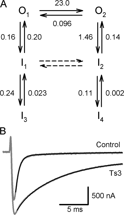
Figure 11.
Kinetic model of inactivation. (A) Kinetic diagram showing the open (O) and inactivated (I) states of the channel. Closed states are not shown and are assumed not to participate on the decay phase of the current at 0 mV (see Discussion). O1 is invariably the first activated state. The numbers indicate the rate constants (in ms−1) obtained by fitting the decay of the sodium current in the presence and absence of Ts3. In the presence of Ts3 the transitions between O1 and O2, and between I1 and I2, are blocked. (B) Experimental records in the presence and absence of Ts3 are superimposed with the theoretical curve calculated using the model and its rate constants.
RESULTS
Effects of Ts3 on Nav1.4 Sodium Currents
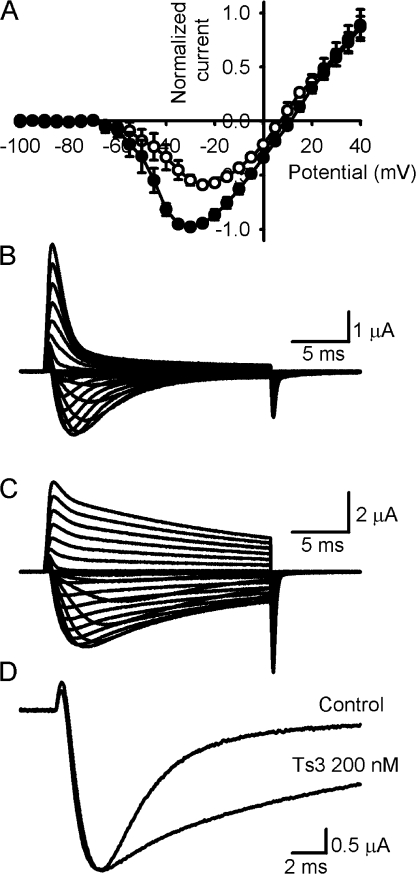
Fig. 1 shows sodium currents recorded at 14°C.Fig. 1 A compares the I-V curves obtained in control conditions and in the presence of 200 nM of Ts3. As reported previously (Campos et al., 2004), the presence of Ts3 increased the amplitude of the sodium current but did not change significantly the voltage dependence of the activation. Nav1.4 sodium current decay with a fast time course in control conditions (Fig. 1 B). In the presence of 200 nM of Ts3 the decay of the currents became slower and the peak current increased (Fig. 1, C and D). As the same effect was observed at a higher concentration of Ts3 (1 μM, not depicted) we considered 200 nM to be a saturating concentration, and this same amount of toxin was used for all the experiments unless otherwise stated. As we have shown before, Ts3 binds tightly to the channel and is removed only if high depolarizing pulses are applied, with higher voltages than that needed for full activation.
Figure 1.
Effect of Ts3 on sodium currents from Xenopus oocytes expressing Nav1.4. (A) I-V curves obtained before (white circles) and after (black circles) the treatment with 200 nM of Ts3. Both curves were normalized by the maximal current obtained in the presence of toxin. Data shown as mean ± SEM (n = 4). Sodium currents were recorded with 20-ms pulses varying from −100 to +40 mV, which were followed and preceded by a 100-ms pulse to −100 mV. The holding potential was −90 mV. (B) Representative traces obtained in control conditions. (C) Representative traces obtained after the treatment with 200 nM of Ts3. (D) Superimposed recordings obtained at −20 mV before and after the treatment with Ts3. The traces were normalized by the peak value. Experiments were performed at 14°C.
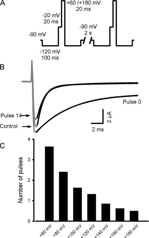
Fig. 2 A shows the pulse protocol used to remove the toxin from muscle sodium channels.Fig. 2 B compares the sodium currents obtained by applying this protocol in control conditions, after the treatment with saturating Ts3, and after 14 depolarizing pulses to +120 mV following the washout of Ts3. The close similarity of the latter with the control record is accounted for by the displacement of Ts3 from the channel, since a further addition of the toxin restores its typical effect (unpublished data). To quantify the removal, the decay of each trace was fitted to a double exponential function (see Materials and methods). In control conditions the contribution of the fast component to the current decay was much larger than the contribution of the slow component (a = 93.7%; b = 6.3%; τf = 1.1 ms; τs = 16.8 ms).
Figure 2.
Ts3 voltage-dependent displacement. (A) Pulse protocol used to remove the bound Ts3. A strong depolarizing pulse, varying from +60 to +180 mV during 20 ms, was applied just after a −20 mV test pulse. Between pulses the oocytes were held at −90 mV, and the protocol was repeated at least 15 times. (B) Traces (gray lines) obtained in control conditions, in the presence of Ts3 (Pulse #0) and after 14 successive depolarization to +120 mV, by applying the protocol described above (Pulse #14) in the absence of Ts3. Black lines shows the curves obtained by fitting the data with function 1 (see Materials and methods). (C) Voltage dependence of toxin removal, obtained by applying the pulse protocol described in A. The graph shows the data obtained from a representative experiment. The number of pulses needed to an e-fold displacement was calculated by fitting the slow component contribution decay with a single exponential function.
After the treatment with Ts3 the contribution of the slow component increased (a = 5.4%; b = 94.6%; τf = 1.0 ms; τs = 6.5 ms). After each depolarizing pulse, the contribution of the slow component decreased proportionally, and after the pulse series the parameters obtained were similar to those seen in control conditions (a = 86.6%; b = 13.4%; τf = 1.2 ms; τs = 6.7 ms). The decrease of the slow component fitted well a single exponential function, and the number of pulses needed for an e-fold decrease of the slow component was used to assess the voltage dependence of the toxin removal, as shown in Fig. 2 C.
Ts3 Modifies Nav1.4 Gating Currents
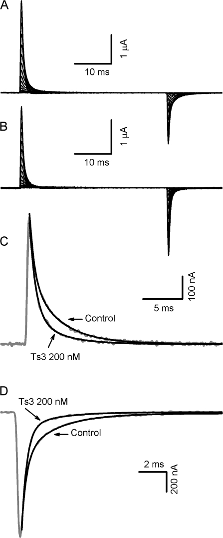
Similar to other site 3 toxins, previous reports suggest that the S4 segment of domain IV has a main role in the interaction between sodium channels and Ts3 (Campos et al., 2004; Campos and Beirão, 2006). To further investigate this point, we measured the effects of Ts3 on Nav1.4 gating currents. After blocking the ionic currents with TTX, the gating currents were recorded at 14°C, to improve the resolution of their decay phase. Fig. 3 shows representative traces obtained before (A) and after (B) the treatment with a saturating concentration of Ts3. A comparison of traces obtained at −40 mV in both conditions shows that, in the presence of the toxin, both ON and OFF gating currents decay faster (Fig. 3, C and D). As expected, the effect of Ts3 on gating currents was also reverted at stronger depolarizing pulses (unpublished data).
Figure 3.
Effects of Ts3 on Nav 1.4 sodium channel gating currents. (A) Superimposed representative gating currents obtained in control conditions. Holding potential was −80 mV. ON gating currents were recorded with 40-ms pulses varying from −150 to +40 mV following a 100-ms prepulse to −120 mV. OFF gating currents were recorded with 40-ms pulses to −120 mV, preceded by pulses varying from −150 to +40 mV. (B) Superimposed representative gating currents obtained after the treatment with 200 nM of Ts3, by applying the protocol described in A. Experiments were performed at 14°C. (C) Comparison of traces of the ON gating currents obtained at −40 mV (gray lines) before and after the treatment with Ts3. Solid lines show the best fits obtained with function 1. (D) Comparison of traces of the OFF gating currents obtained at −120 mV after a pulse to −40 mV (gray lines) before and after the treatment with Ts3. Solid lines show the best fits obtained with function 1.
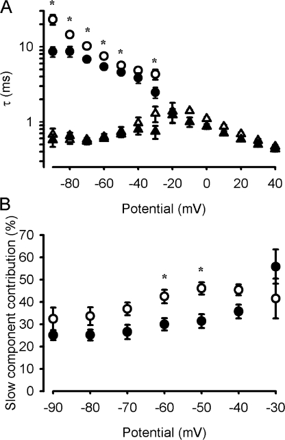
It has been shown that the decay of the ON gating currents of sodium channels may be fitted to two components, and that the slow component is correlated with the movement of the voltage sensor of domain IV (Chanda and Bezanilla, 2002). The effects of Ts3 on the ON gating current kinetics were quantified by fitting the decay phase of the currents with a double exponential function (see Materials and methods). Fig. 4 A compares the voltage dependence of the fast and slow time constants of the gating current decay, obtained before and after the treatment with Ts3. From −90 until −30 mV the best fits were obtained with a double exponential function, but at more positive potentials, the two components merge into only one component. After the treatment with Ts3, the slow time constants became significantly faster while the fast time constant remained unaffected. Furthermore, Ts3 decreased the relative contribution of the slow component to the decay (Fig. 4 B). One should note that only at −50 and −60 mV the change in the relative contribution of the slow components was statistically significant. This could be due to the fact that at very hyperpolarized or depolarized potentials it is harder to distinguish the fast from the slow component. The specific effect of Ts3 on the slow component of the gating current decay supports the hypothesis that the bound toxin affects the movement of the S4 segment of domain IV.
Figure 4.
Effects of Ts3 on the kinetic parameters of the ON gating currents. The parameters were obtained by fitting the ON gating current decay with function 1. Gating currents were recorded as described in Fig. 3 A. (A) Fast and slow time constants of the gating current decay. (B) Contribution of the slow component to the gating current decay. White circles show the slow component in control conditions and the black circles show the slow component in the presence of Ts3. Data shown as mean ± SEM, n = 4. *, existence of statistical difference (P < 0.05) between compared groups.
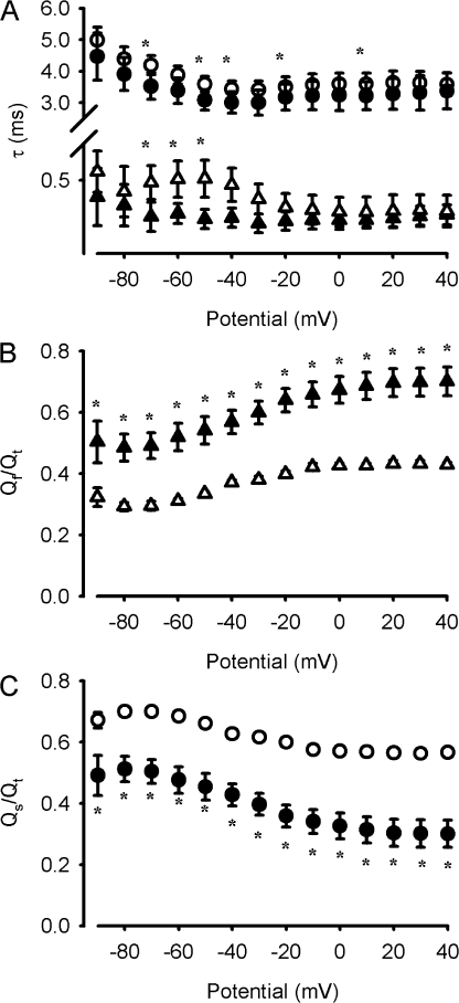
The kinetics of the OFF gating currents normally has two components: the fast component corresponds to the charge that moves independently of inactivation and the slow component corresponds to the remobilization of the inactivated charge and has the time course of the recovery from inactivation (Armstrong and Bezanilla, 1977; Bezanilla, 2000). The effects of Ts3 in the OFF gating current kinetics were quantified by fitting the decay phase of the currents with a double exponential function (see Materials and methods). Fig. 5 A compares the voltage dependence of the fast and slow time constants of the gating current decay, obtained before and after the treatment with Ts3. The slow component is accelerated after Ts3, consistent with the finding that this toxin speeds up the recovery from inactivation (Campos et al., 2004). However, one should note that the effect of Ts3 on the slow time constant of the OFF currents was not significant for all the potentials studied, suggesting that the slow component is not completely eliminated by the toxin. We next determined the effect of the toxin on the fraction of charge that gets immobilized by inactivation. The charge in the slow component (qs) was calculated by the integration of the fitted curve corresponding to the slow component of the decay, which was obtained by the fitting of the gating currents with function 1. The charge in the fast component (qf) was computed from the subtraction of the time integral of qs from the total charge qt, which in turn was obtained by integrating the gating current trace. The fraction of charge in the fast component was computed as Qf = qf/qt and in the slow component by Qs = qs/qt. Fig. 5 (B and C) compares, respectively, the voltage dependence of the fraction of charge in the fast and slow components of the decay, before and after the treatment with Ts3. Before Ts3 the slow component represents 60–70% of the charge, which is the typical charge immobilization reported as a consequence of inactivation, leaving ∼30–40% of the charge returning quickly (Armstrong and Bezanilla, 1977). After Ts3 treatment, there is a clear increase of the fast charge (up to 65%) while the slow charge decreases down to 35%, consistent with the result that fast inactivation, which gives origin to the slow charge, has been drastically reduced by the toxin.
Figure 5.
Effects of Ts3 on the kinetic parameters of the OFF gating currents. The parameters were obtained by fitting the OFF gating current decay with function 1. Gating currents were recorded as described in Fig. 3 A. (A) Fast and slow time constants of the gating current decay. (B) Fraction of charge carried by the fast component of the OFF gating current decay. (C) Fraction of charge carried by the slow component of the decay. White triangles show the fast component in control conditions, black triangles show the fast component in the presence of Ts3, white circles show the slow component in control conditions, and the black circles show the slow component in the presence of Ts3. Note that for some of the potentials, the error bars are smaller than the symbols. Data shown as mean ± SEM, n = 4. *, existence of statistical difference (P < 0.05) between compared groups.
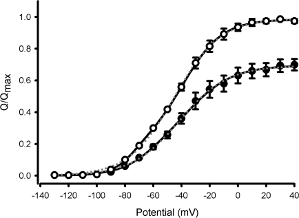
Fig. 6 compares the Q-V relationships obtained before and after the treatment with Ts3. In the presence of Ts3 the total gating charge was reduced by 30%, as reported before with another site 3 toxin from the sea anemone (Sheets and Hanck, 1995). It is expected that at least part of this inhibited charge derives from the movement of the S4 segment of domain IV. The Q-V curves were fitted with either single or double Boltzmann functions (Eq. 2, making qb equal to zero or leaving it as a variable, respectively). The fitting with a double Boltzmann function consistently gave results with lesser deviation from the experimental points, as measured by the sum of squared residuals, thus suggesting the presence of a component that contributes with 30% of the charge and with a V1/2 of −70 mV. More interesting is the fact that Ts3 decreases mainly the charge of this component (Table I). In one experiment this component disappeared altogether in the presence of Ts3. This observation will benefit from more detailed investigation.
Figure 6.
Effects of Ts3 in the charge–voltage relationship. White symbols represent the Q-V curve obtained in control conditions (mean ± SEM, n = 3), and black symbols the curve obtained after the treatment with 200 nM of Ts3 (mean ± SEM, n = 3). The amount of charge recorded in each potential was normalized to the maximum charge recorded before the treatment with Ts3. Solid black lines are the curves obtained by fitting the data with a double Boltzmann function (function 2). Dotted gray lines are the curves obtained by fitting the data with a single Boltzmann function. Experiments were performed at 14°C.
TABLE I.
Voltage Dependence of the Charge Movement (Q × V) in Nav1.4 Channels Expressed in Xenopus Oocytes
| Fitted parameter | Control | Ts3 200 nM | Controlb | Ts3 200 nMb |
|---|---|---|---|---|
| qa | 0.27 ± 0.04 | 0.064 ± 0.007a | 0.995 ± 0.006 | 0.69 ± 0.03a |
| za | 2.98 ± 0.27 | 4.74 ± 0.60a | 1.55 ± 0.12 | 1.47 ± 0.11 |
| V1/2a | −71.1 ± 2.5 | −78.5 ± 1.5 | −44.5 ± 1.3 | −40.4 ± 2.6 |
| qb | 0.71 ± 0.04 | 0.65 ± 0.04 | 0 | 0 |
| zb | 2.02 ± 0.29 | 1.87 ± 0.01 | 0 | 0 |
| V1/2b | −34.0 ± 3.1 | −42.2 ± 0.4 | 0 | 0 |
Values are averages of four independent experiments ± SEM. All experiments were carried out at 14°C.
Values statistically different from control (P < 0.05).bSingle Boltzmann fit.
Ts3 Affects the Site-specific Fluorescence Changes of Domain IV
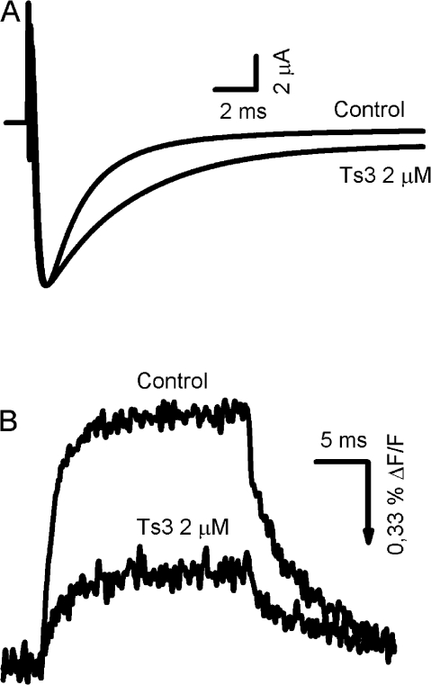
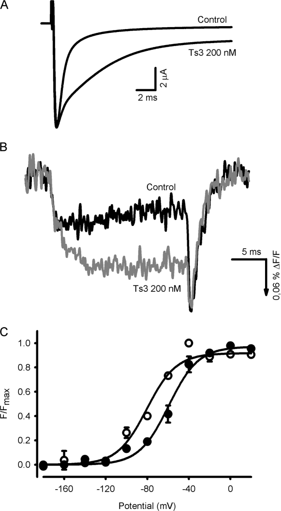
If Ts3 blocks the movement of the charges located in the S4 segment of domain IV, the site-specific fluorescence signals from this particular domain must be affected by the toxin. To address this question we used two well-characterized mutants, S1436C and L1439C (Chanda and Bezanilla, 2002), to simultaneously record fluorescence changes and sodium currents before and after the treatment with Ts3. For the experiments with the mutant S1436C, the concentration of Ts3 had to be increased 10 times to reach a near-maximal effect, as this particular mutation decreased the toxin affinity. Fig. 7 compares records of sodium currents (A) and fluorescence signals (B) obtained at −20 mV before and after the treatment with Ts3 in the S1436C mutant channel. One may notice that, even though the sodium current decay became slower in the presence of Ts3, the effect in the S1436C channel is less pronounced than that observed in wild-type channels. Nevertheless, the toxin decreased the fluorescence signal by 60%, suggesting that at least part of the movement of this voltage sensor was blocked.
Figure 7.
Effects of Ts3 in the fluorescence changes that track the movement of the S4 segment of domain IV of mutant channels S1436C stained with TMRM. Holding potential was −80 mV and the test pulse was preceded by a 200-ms pulse to −90 mV. (A) Representative sodium currents recorded at −20 mV before and after the treatment with 2 μM Ts3. (B) Representative fluorescence signals obtained at −20 mV before and after the treatment with 2 μM of Ts3. The signals are shown as ΔF/F (%), where F is the fluorescence background. The arrow indicates the direction in which fluorescence increases. These experiments were performed at room temperature.
To further verify this effect, we used a different mutant channel (L1439C). In this mutant, the binding affinity for the toxin was similar to that observed in wild-type channels, thus allowing a more direct comparison. The fluorescence of unmodified L1439C shows two components, indicating that the fluorophore samples two different environments (Chanda and Bezanilla, 2002). The early component causes an increase in fluorescence and late component quenches the fluorescence. This causes a characteristic “hooked” tails seen in fluorescence recordings from L1439C. Fig. 8 compares traces of sodium currents (A) and fluorescence signals (B) obtained at −20 mV before and after the treatment with Ts3. In the presence of Ts3, the fluorescence of L1439C showed an increase in fluorescence. We interpret this increase to suggest that fluorescence of the second quenching component is diminished considerably. This two-step movement interpretation also accounts for diminished size of the hook in the tail in toxin-modified channels. Ts3 shifted the F-V curves of L1439C channels by 20 mV in the positive direction (Fig. 8 C; see Table II for fitted parameters).
Figure 8.
Effects of Ts3 on the fluorescence changes that track the movement of the S4 segment of domain IV of mutant channels L1439C stained with TMRM. Traces were recorded as described in Fig. 6. (A) Sodium currents recorded at −20 mV before and after the treatment with 200 nM Ts3. (B) Fluorescence signals obtained at −20 mV before (black trace) and after (gray trace) the treatment with 200 nM of Ts3. The signals are shown as ΔF/F (%), where F is the fluorescence background. The arrow indicates the direction in which fluorescence increases. These experiments were performed at room temperature. (C) F-V curves obtained before (white symbols) and after (black symbols) the treatment with 200 nM of Ts3 (mean ± SEM, n = 3; paired experiments). Solid lines are the curves obtained by fitting the data with the function 3.
TABLE II.
Voltage Dependence of the Florescence Changes (F × V) in Mutated Nav1.4 Channels Expressed in Xenopus Oocytes
| Control
|
Ts3 200 nM
|
|||
|---|---|---|---|---|
| z | V (mV) | z | V (mV) | |
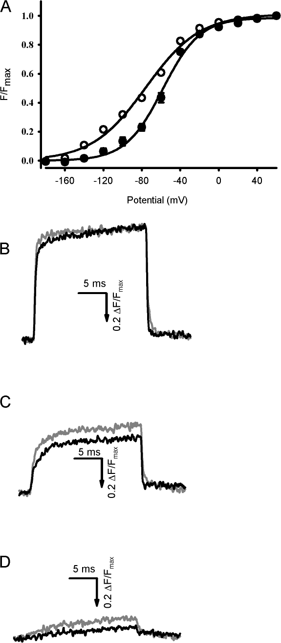
| S4DI (S216C) | 0.921 ± 0.004 | −76.7 ± 1.2 | 1.28 ± 0.11a | −57.6 ± 1.9a |
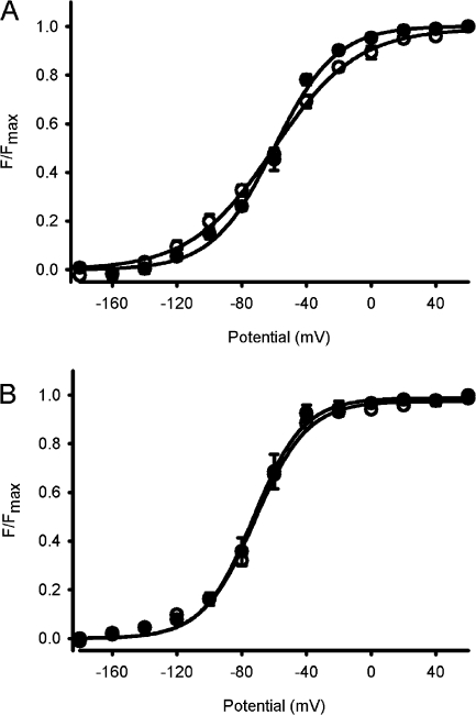
| S4DII (S660C) | 0.96 ± 0.02 | −59.8 ± 3.4 | 1.34 ± 0.07a | −60.2 ± 2.4 |
| S4DIII (L1115C) | 1.47 ± 0.07 | −70.6 ± 0.7 | 1.61 ± 0.09 | −72.1 ± 4.4 |
| S4DIV (L1439C) | 2.26 ± 0.18 | −78.2 ± 6.9 | 1.73 ± 0.09 | −59.3 ± 4.3a |
Values are averages of three independent experiments ± SEM.
Values statistically different from control (P < 0.05).
It is important to point out that since the residues S1436C and L1439C are located in the neighborhood of the α toxin binding site, the effects on the fluorescence changes observed in the presence of Ts3 could be due to an effect of the toxin directly on the TMRM-labeled residues themselves, rather than an effect on the movement of S4-DIV. We believe that this alternative explanation of the fluorescence change is less likely than our interpretation of a direct correlate of the fluorescence change with a modification of the movement of the S4 domain IV by the toxin because it is supported by the other results presented in this paper.
Nav1.4 Voltage Sensors Work in a Cooperative Way
To verify whether the movement of the other voltage sensors is affected by Ts3, we used mutants in the S4 segments of domain I (S216C), domain II (S660C), and domain III (L1115C). This approach is important because several evidences suggest that the four voltage sensors of the sodium channel move in a cooperative way in response to changes in the membrane potential (Chanda et al., 2004; Campos et al., 2007). Thus, by inhibiting the movement of the fourth voltage sensor, Ts3 could also affect the movement of the other voltage sensors. Fig. 9 shows the effects of Ts3 on S216C channels. Ts3 shifted the F-V curves of S216C channels by 20 mV in the positive direction (Fig. 9 A). Moreover, the slope of the curve became steeper after the treatment with the toxin (see Table II for fitted parameters). On the other hand, the fluorescence signal kinetics was not significantly affected by the toxin in any of the studied potentials (Fig. 9, B–D). The fluorescence signal recorded at each potential was normalized by the maximal fluorescence recorded in control conditions or in the presence of Ts3. To analyze the effects of the Ts3 in the fluorescence changes of the voltage sensor of domains II and III we used the S660C and L1115C mutants. Fig. 10 A compares the F-V curves obtained before and after the treatment with Ts3 for the mutant S660C. There was no shift on the curve in this case, but its steepness was slightly, yet significantly, increased (see Table II for fitted parameters).
Figure 9.
Effects of Ts3 in the fluorescence changes that track the movement of the S4 segment of domain I of mutant channel S216C stained with TMRM. Traces were recorded as described in Fig. 7. (A) F-V curves obtained before (white symbols) and after (black symbols) the treatment with 200 nM Ts3 (mean ± SEM, n = 3). The fluorescence recorded at each potential was normalized to the maximal fluorescence. Solid lines are the curves obtained by fitting the data with function 3. (B–D) Superimposed representative traces obtained at +60 (B), −60 (C), and −120 (D) before (gray traces) and after (black traces) the treatment with 200 nM of Ts3. The signals are shown as ΔF/F (%), where F is the fluorescence background. The arrow indicates the direction in which fluorescence increases. These experiments were performed at room temperature.
Figure 10.
Effects of Ts3 in the fluorescence changes that track the movement of the S4 segment of domains II and III, using the mutant channel S660C and L1115C stained with TMRM. Traces were obtained as described in Fig. 7. (A) F-V curves obtained from S660C channels before (white symbols) and after (black symbols) the treatment with 200 nM Ts3 (mean ± SEM, n = 3). The fluorescence recorded at each potential was normalized to the maximal fluorescence. Solid lines are the curves obtained by fitting the data with the function 3. (B) F-V curves obtained from L1115C channels before (white symbols) and after (black symbols) the treatment with 200 nM Ts3 (mean ± SEM, n = 3). The fluorescence recorded at each potential was normalized to the maximal fluorescence. Solid lines are the curves obtained by fitting the data with function 3.These experiments were performed at room temperature.
Fig. 10 B shows the F-V curves obtained before and after the treatment with Ts3 for the L1115C mutant. None of the voltage-dependent parameters were significantly modified in this mutant (see Table II for fitted parameters). The kinetic parameters of both domains II and III were not significantly affected by the toxin (unpublished data). The results shown above agree with those obtained by Chanda et al. (2004), in which they observed that a perturbation in the voltage sensor of domain IV had the largest effect on domain I, with minor effects on domains II and III.
DISCUSSION
Several lines of evidence suggest that the sodium channel voltage sensors do not contribute equally to the control of inactivation. The S4 segments of domains III and IV seem to be immobilized in an outward position by inactivation, while those of domains I and II are not (Cha et al., 1999). While the movement of the S4 segment of domain IV appears to be crucial for inactivation, its role in activation of the channel remains controversial (Chahine et al., 1994; Kuhn and Greeff, 1999; Horn et al., 2000; Chanda and Bezanilla, 2002). Site 3 toxins exert their effect on sodium channel function by binding to the S3–S4 loop of domain IV of the sodium channel. To understand their mechanism of action on sodium channel voltage sensor, we have combined site-specific fluorescence and electrophysiology.
The Effects of Ts3 on Sodium Channels Gating Currents
We observed that the effects of Ts3 in the sodium currents recorded from muscle sodium channels (Nav1.4) expressed on Xenopus oocytes were similar to those observed in other preparations such as GH3 cells, that constitutively express Nav1.1, Nav1.2, Nav1.3, and Nav1.6 (Vega et al., 2003). In addition, all these isoforms have the same number of basic residues in the S4 segment of domain IV.
In the presence of Ts3, the total gating charge was decreased by 30%, whereas the voltage dependence of the charge movement was not significantly affected by this condition. Similar results were obtained by Sheets and Hanck (1995) on gating currents from cardiac sodium channels when treated with the site 3 toxin Ap-A, purified from sea anemone. In addition, when the three outermost arginines of the S4 segment of domain IV were replaced by cysteine or glutamine, inactivation was partially inhibited and the inhibition in the total gating charge observed in the presence of Ap-A was decreased (Sheets et al., 1999). These results provide evidence that site 3 toxins act by inhibiting the movement of charges located in the S4 segment of domain IV.
The S4 segment of domain IV moves with a slower kinetics upon depolarization compared with the S4 segments of the other domains (Chanda and Bezanilla, 2002). At test pulses lower than −30 mV, the ON gating current decays with two kinetically distinct components (see Fig. 4 A). The slow component correlates well with the movement of the S4 segment of domain IV, while the fast component correlates with the movements of the other voltage sensors. It was also noted a correlation between the voltage dependence of the fast time constants of the gating current decay, the time constants of the activation process and the time constants of the fluorescence signals that track the movements of the three first voltage sensors. On the other hand, there was a correlation between the voltage dependence of the slow time constants of the gating current decay and the voltage dependence of the time constants of the fluorescence signals of the S4 segment of domain IV. However, these time constants were always faster than the inactivation of the conductance time constants (Chanda and Bezanilla, 2002). So, if Ts3 acts by maintaining the S4 segment of domain IV in its deactivated position, the slow component of the gating current decay must be affected by the toxin. Indeed we observed that the gating currents recorded in the presence of Ts3 decayed faster than those recorded in control conditions. We observed that in the presence of Ts3 the slow time constants became faster and the contribution of the slow component to the gating current decay was decreased. On the other hand, the fast component of the gating current decay was not significantly affected by the toxin. These results support the interpretation that the site 3 toxins partially inhibit the movement of the S4 segment of domain IV. In addition, we observed that Ts3 also speeds up the kinetic of the OFF gating currents. In the presence of Ts3, the slow charge of the OFF gating currents was significantly decreased. The slow component becomes visible when the potential in which the OFF currents are recorded is negative enough to recover the fraction of charge immobilized by the inactivation (Armstrong and Bezanilla, 1977). This means that the fraction of inactivated channels has been decreased by Ts3, and as the time constant of the slow component has also been sped up by Ts3, the overall effect of Ts3 is an increase in the recovery from inactivation. In line with these results, Campos et al., (2004) has previously shown that in the presence of Ts3 the sodium channels recover from inactivation with faster kinetics.
Effects of Ts3 in the Site-specific Fluorescence Changes Related to the Movement of the Fourth Voltage Sensor
Gating currents reflect the movements of the charges located in all four voltage sensors. Site-specific fluorescence measurements, on the other hand, reflect changes occurring only in the vicinity of where the fluorophore is attached. By applying this technique one can discriminate between the components forming the gating currents (Bezanilla, 2000). It is important to note that fluorescence signals reflect local conformational changes only, so the signal depends on the position of the residue in which the fluorophore is attached, as well as on the environments the fluorophore will pass through during the transition. It was shown that fluorophores attached to cysteines in the positions 1436 and 1439 (a serine and a leucine in wild-type channels, respectively), both located in the S4 segment of domain IV of muscle sodium channels, exhibited different fluorescence signals, but with a similar initial time course (Chanda and Bezanilla, 2002). We observed that the fluorescence signal recorded from S1436C channels was inhibited by 60% in the presence of Ts3. A total inhibition of the fluorescence changes would be expected if the toxin caused a complete blocking of the voltage sensor movement. However, this mutation decreased the affinity of Ts3, which may partly account for incomplete inhibition. Note that we have used 10 times higher concentration and the effect was not maximal. L1439C mutants were used to overcome this limitation, since they exhibited maximal toxin effect at 200 nM. In L1439C channels, the bound toxin produced an increase in the fluorescence signal upon depolarization. This could reflect a sequential transition of the voltage sensor through two distinct environments during depolarization in the absence of toxin. Under these conditions, while the transition through the first environment would produce an increase in the fluorescence, the transition through the second one would reduce it. Upon repolarization, the voltage sensor must pass through the environment in which the fluorescence increases, accounting for the tail observed in these conditions, before reaching the full deactivated position. In presence of Ts3 the second step of this movement would be inhibited, which explains the increase observed in the total fluorescence signal. Accordingly, Ts3 acts by partially blocking the movement of the S4 segment of domain IV, which would be enough to inhibit the inactivation but still allowing a normal activation to occur. The hypothesis that the voltage sensors move in at least two sequential and distinct steps has been proposed earlier to explain the gating of Shaker and EAG potassium channels (Bezanilla et al., 1994; Baker et al., 1998; Lecar et al., 2003; Silverman et al., 2003), and also for human muscle sodium channels (Horn et al., 2000). According to these authors, there is an intermediate state between the activated and deactivated positions, and the transitions toward this intermediate state from activated or deactivated present distinct charge components. Our data provide direct evidence supporting this hypothesis.
Effects of Ts3 in the Movement of the Other Voltage Sensors
Several evidences suggest that the sodium channel voltage sensors move in a cooperative way (Vandenberg and Bezanilla, 1991; Keynes and Elinder, 1998; Chanda et al., 2004; Campos et al., 2007). It was shown that by neutralizing charges in the S4 segment of domain IV, the movement of the voltage sensor of domain I was affected, while the movement of the voltage sensors of domains II and III remained unaffected (Chanda et al., 2004). Interestingly, we observed that the voltage dependence of the fluorescence changes related to the movement of the voltage sensors of domains II and III remained the same in the presence of Ts3, while in these conditions the voltage dependence of the fluorescence curves of the S4 segment of domain I was shifted by 20 mV toward more positive potentials (Fig. 9). Although the site 3 toxin binding site includes some residues located on domain I, they seem not to be crucial for toxin binding (Cestèle and Catterall, 2000), and Ts3 does not significantly alter current activation. The cooperativity of the movement of the voltage sensors of domains I and IV can account for the results shown in Fig. 9.
Mechanism of Action of Site 3 Toxins
One important feature regarding the interaction between the site 3 toxins and the sodium channel is that it occurs in a voltage-dependent way, decreasing at depolarized potentials (Catterall et al., 1976; Catterall, 1977a,b; Mozhayeva et al., 1980; Strichartz and Wang, 1986; Rogers et al., 1996; Chen et al., 2000). Washing off toxin Ts3 does not remove it from the site 3 of the sodium channel, and its effect can be observed for long periods when 0-mV test pulses were applied. At that potential, the activation of the channel is complete, implying that activation does not remove the toxin (Campos et al., 2004; Fig. 2). However, the effects of the toxin could be removed by applying stronger depolarizing pulses. Similar results have been reported in GH3 cells (Campos and Beirão, 2006).
Our results can be interpreted with a kinetic model modified from Campos et al. (2004). The basic concept is that there are at least two open states of the sodium channel (see Fig. 11): O1, from which inactivation proceeds at a slow rate; and O2, from which inactivation is fast. In control conditions, the transition from O1 to O2 is very fast, and inactivation occurs at a fast rate. We propose that Ts3 blocks this transition, thus forcing the channel to inactivate at a slower rate. The results presented in the present paper show that the transition from O1 to O2 is related to the movement of the segment S4 of domain IV, which is inhibited, at least partially, by Ts3 (Figs. 5 and 6). Our data suggest that there is but a short movement of this segment, because the fluorescence changes related to it are not blocked completely. Whether this short movement is necessary for opening the channel remains to be elucidated. Horn et al. (2000) reported evidence that holding the S4 segment of domain IV in its resting position prevents the opening of the channel. We propose that in the O1 state the S4 segment of domain IV is at an intermediate state.
To estimate the rate constants associated with the transitions between the states shown in Fig. 11, we fitted the decay phase of the sodium current in the absence and in the presence of Ts3. The expected current was modeled using the Matrix Q procedure, as described by Campos et al. (2004), based on Colquhoun and Hawkes (1995). It is assumed that at the potential of 0 mV there is no channel opening during the decay phase, and therefore the transitions between resting states and open states could be disregarded when fitting this phase. This assumption is supported by two calculations at that potential: (1) the peak conductance has achieved 95% the maximal level (Fig. 6); and (2) the gating charge associated with activation (measured in the presence of Ts3) has reached 96% of its completion at the start of the exponential decay of the sodium current (measured from Fig. 3). Fig. 11 shows that the data can be fitted with this model using the rate constants shown in the diagram. Note that the transition between I1 and I2, which corresponds to the completion of the movement of segment S4 of domain IV after the channel has achieved inactivation, is expected to occur in control conditions, but not in the presence of Ts3. However, the rate constants related to these transitions could not be assessed because, as predicted by the model, <0.4% of the channels will normally pass via I1. I3 and I4 were introduced for fitting purposes, and their molecular significance remains to be established. The model also explains why stronger depolarization is able to remove the bound toxin. In these conditions an additional energy is applied to the S4 segment of domain IV, and then the voltage sensor is now able to pass through the barrier formed by the bound toxin, reaching its most activated position. The significant voltage dependence of this process supports this interpretation.
Acknowledgments
The authors are indebted to Dr. L.D. Possani (Universidad Autonoma de Mexico, Mexico City, Mexico) for generously providing samples of highly purified Ts3.
A grant from the Brazilian Research Council (CNPq) to P.S.L. Beirão is acknowledged. F.V. Campos was recipient of a fellowship of the same Brazilian Agency. This work was supported by National Institutes of Health grant GM30376. B. Chanda was supported by a Scientist Development grant from the American Heart Association.
Angus C. Nairn served as editor.
Abbreviations used in this paper: Mes, Na-methylsulfonate; NMG, N-methylglucamine; TMRM, 5′-tetramethylrhodamine maleimide.
References
- Armstrong, C.M., and F. Bezanilla. 1977. Inactivation of the sodium channel. II. Gating current experiments. J. Gen. Physiol. 70:567–590. [DOI] [PMC free article] [PubMed] [Google Scholar]
- Baker, O.S., H.P. Larsson, L.M. Mannuzzu, and E.Y. Isacoff. 1998. Three transmembrane conformations and sequence-dependent displacement of the S4 domain in shaker K+ channel gating. Neuron. 20:1283–1294. [DOI] [PubMed] [Google Scholar]
- Benzinger, G.R., J.W. Kyle, K.M. Blumenthal, and D.A. Hanck. 1998. A specific interaction between the cardiac sodium channel and site-3 toxin anthopleurin B. J. Biol. Chem. 273:80–84. [DOI] [PubMed] [Google Scholar]
- Bezanilla, F. 2000. The voltage sensor in voltage-dependent ion channels. Physiol. Rev. 80:555–592. [DOI] [PubMed] [Google Scholar]
- Bezanilla, F., E. Perozo, and E. Stefani. 1994. Gating of Shaker K+ channels: II. The components of gating currents and a model of channel activation. Biophys. J. 66:1011–1021. [DOI] [PMC free article] [PubMed] [Google Scholar]
- Campos, F.V., F.I. Coronas, and P.S.L. Beirão. 2004. Voltage-dependent displacement of the scorpion toxin Ts3 from sodium channels and its implication on the control of inactivation. Br. J. Pharmacol. 142:1115–1122. [DOI] [PMC free article] [PubMed] [Google Scholar]
- Campos, F.V., and P.S.L. Beirão. 2006. Effects of bound Ts3 on voltage dependence of sodium channel transitions to and from inactivation and energetics of its unbinding. Cell Biochem. Biophys. 44:424–430. [DOI] [PubMed] [Google Scholar]
- Campos, F.V., B. Chanda, B. Roux, and F. Bezanilla. 2007. Two atomic constraints unambiguously position the S4 segment relative to S1 and S2 segments in the closed of Shaker K channel. Proc. Natl. Acad. Sci. USA. 104:7904–7909. [DOI] [PMC free article] [PubMed] [Google Scholar]
- Catterall, W.A. 1977. a. Membrane potential-dependent binding of scorpion toxin to the action potential Na+ ionophore. Studies with a toxin derivative prepared by lactoperoxidase-catalyzed iodination. J. Biol. Chem. 252:8660–8668. [PubMed] [Google Scholar]
- Catterall, W.A. 1977. b. Activation of the action potential Na+ ionophore by neurotoxins. An allosteric model. J. Biol. Chem. 252:8669–8676. [PubMed] [Google Scholar]
- Catterall, W.A., R. Ray, and C.S. Morrow. 1976. Membrane potential dependent binding of scorpion toxin to action potential Na+ ionophore. Proc. Natl. Acad. Sci. USA. 73:2682–2686. [DOI] [PMC free article] [PubMed] [Google Scholar]
- Cestèle, S., F. Sampieri, H. Rochat, and D. Gordon. 1996. Tetrodotoxin reverses brevetoxin allosteric inhibition of scorpion α-toxin binding on rat brain sodium channels. J. Biol. Chem. 271:18329–18332. [DOI] [PubMed] [Google Scholar]
- Cestèle, S., and W.A. Catterall. 2000. Molecular mechanisms of neurotoxin action on voltage-gated sodium channels. Biochimie. 82:883–892. [DOI] [PubMed] [Google Scholar]
- Cha, A., and F. Bezanilla. 1998. Structural implications of fluorescence quenching in the Shaker K1 channel. J. Gen. Physiol. 112:391–408. [DOI] [PMC free article] [PubMed] [Google Scholar]
- Cha, A., P.C. Ruben, A.L. George, E. Fujimoto, and F. Bezanilla. 1999. Voltage sensors in domains III and IV, but not I and II, are immobilized by Na channel fast inactivation. Neuron. 22:73–87. [DOI] [PubMed] [Google Scholar]
- Chahine, M., A.L. George Jr., M. Zhou, S. Ji, W. Sun, R.L. Barchi, and R. Horn. 1994. Sodium channel mutations in paramyotonia congenita uncouple inactivation from activation. Neuron. 12:281–294. [DOI] [PubMed] [Google Scholar]
- Chanda, B., and F. Bezanilla. 2002. Tracking voltage-dependent conformational changes in skeletal muscle sodium channel during activation. J. Gen. Physiol. 120:629–645. [DOI] [PMC free article] [PubMed] [Google Scholar]
- Chanda, B., O.K. Asamoah, and F. Bezanilla. 2004. Coupling interactions between voltage sensors of the sodium channel as revealed by site-specific measurements. J. Gen. Physiol. 123:217–230. [DOI] [PMC free article] [PubMed] [Google Scholar]
- Chen, H., D. Gordon, and S.H. Heinemann. 2000. Modulation of cloned skeletal muscle sodium channels by the scorpion toxins Lqh II, Lqh III and Lqh αIT. Pflugers Arch. 439:423–432. [DOI] [PubMed] [Google Scholar]
- Colquhoun, D., and A.G. Hawkes. 1995. A Q-matrix cookbook. In Single Channel Recording. B. Sakmann and E. Neher, editors. Plenum Press, New York. 589–633.
- Couraud, F., H. Rochat, and S. Lissitzki. 1978. Binding of scorpion and sea anemone neurotoxins to a common site related to the action potential Na+ ionophore in neuroblastoma cells. Biochem. Biophys. Res. Commun. 83:1525–1530. [DOI] [PubMed] [Google Scholar]
- Groome, J.R., E. Fujimoto, A.L. George, and P.C. Ruben. 1999. Differential effects of homologous S4 mutations in human skeletal muscle sodium channels on deactivation gating from open and inactivated states. J. Physiol. 516:687–698. [DOI] [PMC free article] [PubMed] [Google Scholar]
- Horn, R., S. Ding, and H.J. Gruber. 2000. Immobilizing the moving parts of voltage-gated ion channels. J. Gen. Physiol. 116:461–476. [DOI] [PMC free article] [PubMed] [Google Scholar]
- Keynes, R.D., and F. Elinder. 1998. On the slowly rising phase of the sodium gating current in the squid giant axon. Proc. Biol. Sci. 265:255–262. [DOI] [PMC free article] [PubMed] [Google Scholar]
- Kontis, K.J., and A.L. Goldin. 1997. Sodium channel inactivation is altered by substitution of voltage sensor positive charges. J. Gen. Physiol. 110:403–413. [DOI] [PMC free article] [PubMed] [Google Scholar]
- Kuhn, F.J., and N.G. Greeff. 1999. Movement of voltage sensor S4 in domain 4 is tightly coupled to sodium channel fast inactivation and gating charge immobilization. J. Gen. Physiol. 114:167–183. [DOI] [PMC free article] [PubMed] [Google Scholar]
- Lecar, H., H.P. Larsson, and M. Grabe. 2003. Electrostatic model of S4 motion in voltage-gated ion channels. Biophys. J. 85:2854–2864. [DOI] [PMC free article] [PubMed] [Google Scholar]
- Mozhayeva, G.N., A.P. Naumov, E.D. Nosyreva, and E.V. Grishin. 1980. Potential-dependent interaction of toxin from venom of the scorpion Buthus eupeus with sodium channels in myelinated fibre: voltage clamp experiments. Biochim. Biophys. Acta. 597:587–602. [DOI] [PubMed] [Google Scholar]
- Possani, L.D., B.M. Martin, J. Mochca-Morales, and I. Svendsen. 1981. Purification and chemical characterization of the major toxins from the venom of the Brazilian scorpion Tityus serrulatus Lutz and Mello. Carlsberg Res. Commun. 46:195–205. [Google Scholar]
- Rogers, J.C., Y. Qu, T.N. Tanada, T. Scheuer, and W.A. Catterall. 1996. Molecular determinants of high affinity binding of α-scorpion toxin and sea anemone toxin in the S3-S4 extracellular loop in domain IV of the Na+ channel alpha subunit. J. Biol. Chem. 271:15950–15962. [DOI] [PubMed] [Google Scholar]
- Sheets, M.F., and D.A. Hanck. 1995. Voltage-dependent open-state inactivation of cardiac sodium channels: gating current studies with Anthopleurin-A toxin. J. Gen. Physiol. 106:617–640. [DOI] [PMC free article] [PubMed] [Google Scholar]
- Sheets, M.F., J.W. Kyle, R.G. Kallen, and D.A. Hanck. 1999. The Na channel voltage sensor associated with inactivation is localized to the external charged residues of domain IV, S4. Biophys. J. 77:747–757. [DOI] [PMC free article] [PubMed] [Google Scholar]
- Silverman, W.R., B. Roux, and D.M. Papazian. 2003. Structural basis of two-stage voltage-dependent activation in K+ channels. Proc. Natl. Acad. Sci. USA. 100:2935–2940. [DOI] [PMC free article] [PubMed] [Google Scholar]
- Strichartz, G.R., and G.K. Wang. 1986. Rapid voltage-dependent dissociation of scorpion α-toxins coupled to Na channel inactivation in amphibian myelinated nerves. J. Gen. Physiol. 88:413–435. [DOI] [PMC free article] [PubMed] [Google Scholar]
- Stühmer, W., F. Conti, H. Suzuki, X.D. Wang, M. Noda, M. Yahagi, H. Kubo, and S. Numa. 1989. Structural parts involved in activation and inactivation of the sodium channel. Nature. 339:597–603. [DOI] [PubMed] [Google Scholar]
- Vandenberg, C.A., and F. Bezanilla. 1991. A sodium channel gating model based on single channel, macroscopic ionic, and gating currents in the squid giant axon. Biophys. J. 60:1511–1533. [DOI] [PMC free article] [PubMed] [Google Scholar]
- Vega, A.V., J.L. Espinosa, A.M. Lopez-Dominguez, L.F. Lopez-Santiago, A. Navarrete, and G. Cota. 2003. L-type calcium channel activation up-regulates the mRNAs for two different sodium channel α subunits (Nav1.2 and Nav1.3) in rat pituitary GH3 cells. Brain Res. Mol. Brain Res. 116:115–125. [DOI] [PubMed] [Google Scholar]
- Yu, F.H., and W.A. Catterall. 2003. Overview of the voltage-gated sodium channel family. Genome Biol. 4:207. [DOI] [PMC free article] [PubMed] [Google Scholar]


