

Abstract
Although hip simulators for in vitro wear testing of prosthetic materials used in total hip arthroplasty (THA) have been available for a number of years, similar equipment has yet to appear for endurance testing of fixation in cemented THA, despite considerable evidence of late aseptic loosening as one of the most significant failure mechanisms in this type of replacements. An in vitro study of fatigue behavior in cemented acetabular replacements has been carried out, utilizing a newly developed hip simulator. The machine was designed to simulate the direction and the magnitude of the hip contact force under typical physiological loading conditions, including normal walking and stair climbing, as reported by Bergmann et al. (2001, Hip 98, Freie Universitaet, Berlin). A 3D finite element analysis has been carried out to validate the function of the hip simulator and to evaluate the effects of boundary conditions and geometry of the specimen on the stress distribution in the cement mantle. Bovine pelvic bones were implanted with a Charnley cup, using standard manual cementing techniques. Experiments were carried out under normal walking and descending stairs loading conditions with selected load levels from a body weight of 75-125 kg. Periodically, the samples were removed from the test rigs to allow CT scanning for the purpose of monitoring damage development in the cement fixation. The hip simulator was found to be satisfactory in reproducing the hip contact force during normal walking and stair climbing, as reported by Bergmann et al. Finite element analysis shows that the stress distributions in the cement mantle and at the bone-cement interface are largely unaffected by the geometry and the boundary conditions of the model. Three samples were tested up to 17 × 106 cycles and sectioned post-testing for microscopic studies. Debonding at the bone-cement interface of various degrees in the posterior-superior quadrant was revealed in these samples, and the location of the failures corresponds to the highest stressed region from the finite-element analysis. Preliminary experimental results from a newly developed hip simulator seem to suggest that debonding at the bone-cement interface is the main failure mechanism in cemented acetabular replacements, and descending stairs seem to be more detrimental than normal walking or ascending stairs with regard to fatigue integrity of cement fixation.
Keywords: hip simulator, fixation, acetabular cups, fatigue, finite element analysis
1 Introduction
Hip joint simulators are now extensively used in the evaluation of the performance of articulating materials for total hip and knee arthroplasties. Almost exclusively, these simulators have been designed for in vitro wear testing of various degrees of sophistication [1-9]. In theory, six independent actuators are required to simulate the motions and loads of a hip joint. However, most of the existing simulators have been designed by assuming some of the movements and load degrees of freedom are negligible without compromising the essential performance of the simulating device. There are two types of apparatus: motion apparatus that aims to reproduce the motions of a hip joint and load apparatus that simulates the physiological loading wave forms. The development of hip simulators of the second category has been closely associated with the available data base of hip contact force. One of the chosen load/motion cycles [6] representative of normal gait was based on the data of Paul [7] from a simplified muscle model. Data from instrumented hip implants with telemetric data transmission were not available until much later [3,10], with more comprehensive long-term data available only recently [11,12].
Strength requirements for prostheses have been met by simplified mechanical testing, often simulating the limiting locomotion patterns in loading [13]. Since the publication of the hip contact force data measured in vivo by Bergmann et al. [12], the utilization of these data for endurance testing of fixation has yet to emerge. Clinically, cemented total hip arthroplasty (THA) remains the surgical technique used most frequently throughout Europe and has shown excellent long-term results compared to some of the cementless alternatives. However, the increased late loosening rate [14,15], particularly in acetabular components [16], has been well documented as the primary failure mechanism in this type of replacements. It is generally accepted that a multifactorial etiology, both biological and mechanical, may contribute to aseptic loosening [17], although the role of mechanical loading is far less well understood, as opposed to wear and wear-induced failure mechanisms that have been extensively studied over the past two decades or so. It seems highly desirable that physiological loading wave forms are introduced in mechanical testing of cement fixation, so that the role of realistic mechanical loads in the progressive loss of the cement fixation may be evaluated.
To this end, a new hip simulator has been developed for the purpose of fatigue testing of implanted acetabula. The machine (Simulation Solutions Ltd., UK) is capable of accommodating full hemipelvic bone samples and simulating the resultant hip contact force as a three-dimensional force vector via biaxial rotational motions synchronized to the hip contact force. This paper reports the development and evaluation of this unique machine. A 3D finite element analysis has also been carried out to evaluate the function of the simulator as well as selected boundary and geometry conditions of the test sample with regard to the stress distribution in the cement mantle. Preliminary experimental results from the hip simulator testing are also presented and compared to the experimental results from conventional fatigue tests [18].
2 Hip Simulator
The resultant hip contact force [12] relative to the cup coordinate system is reproduced in the hip simulator. The force vector was achieved by synchronizing the magnitude of the force with the rotational displacements about y (angle φ) and z′ (angle θ) axes, where z′ is perpendicular to the obd plane (Fig. 1). The motions of each station are controlled by three electric servomotors, which produce rotations about X, Y, and Z axes in the machine frame (Fig. 2). Although the ranges of the motions allowable are ±35 deg, ±360 deg, and ±60 deg for rotations on YZ, XZ, and XY planes, respectively, only two motions are required to simulate the resultant hip contact force, namely, rotation about the Y axis on the XZ plane and a swing operation about the Z axis on the XY plane. The ranges required for normal walking (XZ, 88 deg; XY, 35 deg), ascending stairs (XZ, 141 deg; XY, 29 deg) and descending stairs (XZ, 193 deg; XY, 44 deg) are well within the capacity of the apparatus. The machine has four stations, which may be individually controlled to allow selected load profiles to operate independently and simultaneously.
Fig. 1.
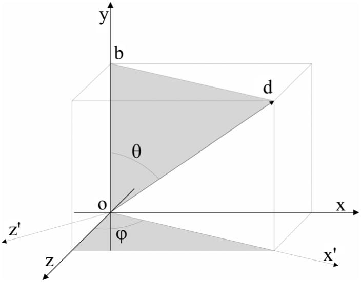
The resultant hip contact force relative to the cup coordinate system. Note that the magnitude and the orientation of the hip contact force may be achieved by two rotationary actuators about y and z′ axes, respectively. z′ is perpendicular to the obd plane. The rotations are represented by angle φ and θ.
Fig. 2.
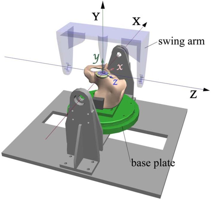
Schematic diagram of the motions of the Portsmouth hip simulator with the coordinate systems shown in the machine frame (X,Y,Z) and cup frame (x,y,z), as used by Bergmann et al. [12]
The test cell was designed to hold a hemipelvic bone with a cemented acetabular cup. The cup is in articulation with a spherical femoral head through which the load is transmitted. The hemipelvic bone specimen is mounted upside down in order to facilitate lubrication during testing. The main constraint of the specimen is achieved at iliac tuberosity via moulds of epoxy putty to apply uniform pressure. A partial constraint is also applied to the pubic joint to maintain the symmetry condition of the pelvis while allowing movements on the sagittal plane. One of the test cells, including a specimen held in the loading device, is shown in Fig. 3. A smoothing procedure was followed to reduce the local irregularities of the average patient data [11], and to link the end and the beginning of a gait to permit continuous cyclic loading. Figure 4 shows the comparison of the hip contact force as a demand signal and the response of the machine for normal walking, ascending, and descending stairs. The relative error is 3.6% for normal walking, 1.5% for ascending, and 6.2% for descending stairs, all at the peak hip contact force. The motions during physiological loading conditions are also evaluated and presented in Fig. 5. Again, the simulator is able to follow the demand signals satisfactorily.
Fig. 3.
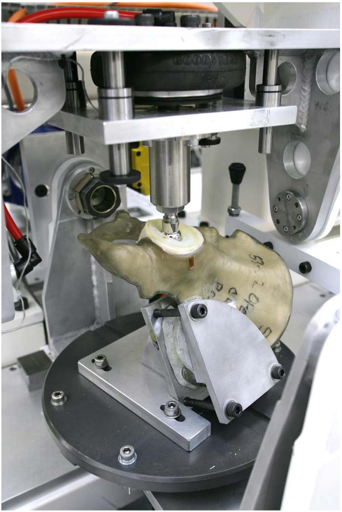
The Portsmouth four station hip simulator with a specimen loaded in one of the test cells
Fig. 4.

Comparison of the hip contact forces as demand signal (line) and response of the machine (symbol) for normal walking (a), ascending stairs (b), and descending stairs (c)
Fig. 5.

Comparison of the motions as demand signal (line) and response of the machine (symbol) for normal walking (a), ascending stairs (b), and descending stairs (c)
3 Finite Element Analysis
3.1 Methods
To evaluate the function of the hip simulator in the realization of the hip contact force as measured in vivo [11,12], a three-dimensional finite element model of a hemipelvic bone with a cemented acetabular cup was developed. A third generation composite sawbone model (Pacific Research Laboratories, Inc., Vashon Island, WA) was laser scanned and processed (Geomagic, Inc., Research Triangle Park, NC) to create a three-dimensional sandwich structure, where a homogenous foam core represents the trabecular bone and a fiber reinforced shell simulates the cortical bone. A standard Charnley cup with outer/inner diameter of 53/22 mm was inserted in a standard position with a cement layer of 3.5 mm thickness. The femoral head was modeled as a rigid body. The cup and the cement mantle were meshed with eight-noded linear brick and six-noded linear wedge elements, with an element size of ∼1 mm, and the total numbers of elements were 2480 and 900, respectively. The hemipelvic bone structure was meshed with a total of 49,878, four-noded linear tetrahedron elements with the element sizes varying between 1 and 2.5 mm. Details of the material properties of the individual parts are given in Table 1.
Table 1. A summary of the material properties used in the FE models.
| Material | Young’s modulus (MPa) | Poisson’s ratio | References |
|---|---|---|---|
| UHDPE | 1,000 | 0.4 | Mak and Jin, 2002 |
| PMMA | 2,000 | 0.33 | Harper and Bonfield, 2000 |
| Pelvis shell | 10,000 | 0.3 | Pacific Research Laboratories, Inc. |
| Pelvis core | 104 | 0.3 | Pacific Research Laboratories, Inc. |
| Bovine trabecular bone | 1,000 | 0.3 | Keaveny et al., 1993 |
Surface-to-surface discretization was used for the contact analysis between the femoral head and the acetabular cup. To allow for contact pair motion, a finite sliding tracking approach was adopted. The cement surfaces were bonded to the cup and the underlying bone structure using a tie contact formulation. The time step for the numerical simulation of a normal walking gait cycle was 1.1 s, the same as that in the experiments, and the initial increment for the step was 0.01 s. The simulation was assumed to be quasistatic without the consideration of the inertial properties of the fixtures holding the specimen. Friction between the femoral head and the acetabular cup was ignored.
Selected boundary conditions were examined and presented in Table 2. Models A and B simulate the constraint conditions of the hip simulator (Fig. 6(a)); constraints in Model C are more consistent with the anatomical condition, i.e., fully constrained at sacroiliac joint and symmetry conditions applied to pubic symphysis. Model D represents a bovine bone model with a truncated geometry and higher constraints (Fig. 6(b)). A static model (A) was loaded first at six selected load cases (2%, 16%, 30%, 50%, 65%, and 100%) of a gait cycle [11], and the results are compared to those from Models B-D. Stair climbing loading profiles have also been examined (Models F and G), in addition to normal walking (Model E) for bovine bone models.
Table 2. Descriptions of the models used in the FE analysis.
| Model | Geometry | Analysis | Bone type | Constraints |
|---|---|---|---|---|
| A | Full hemipelvis | Static | Composite bone | Hip simulator |
| B | Full hemipelvis | Dynamic | Composite bone | Hip simulator |
| C | Full hemipelvis | Dynamic | Composite bone | Anatomical |
| D | Truncated pelvis | Dynamic | Composite bone | Hip simulator |
| E | Truncated pelvis | Dynamic | Bovine bone | Hip simulator |
| F | Truncated pelvis | Dynamic | Bovine bone | Hip simulator |
| G | Truncated pelvis | Dynamic | Bovine bone | Hip simulator |
Fig. 6.
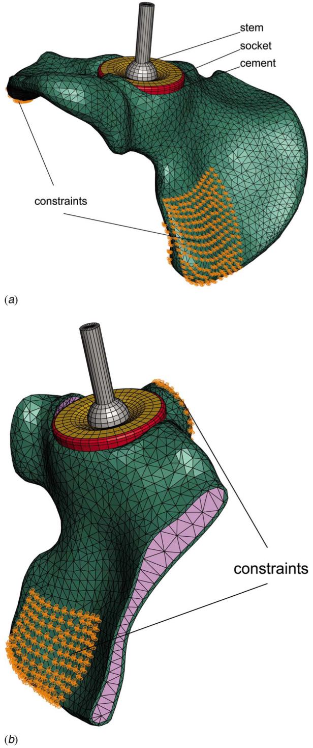
Constraints of the Models A and B, simulation of the constraint conditions of the hip simulator (a) and the constraint conditions of the bovine bone Model D (b)
3.2 Results
The stress distribution in the cement mantle is of primary interest to the fixation of acetabular replacements. As the stress gradient in the cement mantle is small, only the stress distributions on the bone-cement interface are presented (Fig. 7). In general, the von Mises stress distribution in all models at the selected load cases seems to be similar. The maximum von Mises stress appears to occur consistently at ∼16% of a gait cycle in the posterior-superior quadrant, with a normalized stress index α (, where and are the maximum von Mises stress in a given Model X and Model A, respectively) between 1 (Model A) and 1.145 (Model D). The comparable stress contours in Models A and B seem to suggest that the influence of dynamic loading on the cement stress distribution is small. The higher level of constraints applied to Model B (hip simulator) seems to produce only a slight elevation in the cement stress near the posterior-superior edge, compared to Model C (anatomical). Although Model D has a markedly different geometry and constraints from those of Model A, the magnitude and the distribution of the stresses seem to be mostly undisturbed.
Fig. 7.

A summary of von Mises stresses in the cement mantle near the bone-cement interface from selected FE models
The influence of stair climbing profiles on the cement stress distribution is shown in Fig. 8. The stress distribution pattern in ascending stairs seems to be consistent with that in normal walking, although with a higher magnitude (α=1.211) at a single-legged stance. The maximum von Mises stress in descending stairs occurs at a later part of the loading cycle (∼56% as opposed to 18% in ascending stairs), with a higher still magnitude (α=1.412). Clearly, descending stairs represent the worst case scenario amongst the three loading profiles examined here.
Fig. 8.

Comparison of von Mises stresses in the cement mantle near the bone-cement interface under normal walking (E), ascending stairs (F), and descending stairs (G) loading conditions
4 In Vitro Fatigue Testing
4.1 Methods
Composite sawbones were found to be inadequate for hip simulator testing, as the bones failed prior to the failure of the cement fixation. Bovine bones were used instead. The bovine hemipelvises were retrieved from a local abattoir and kept frozen untill use. Excess bone and soft tissues were removed manually and the bones were simmered in water for 30 min at 90°C to remove soft tissues. The bones were then soaked in an enzyme solution (Neutrase, Novozymes A/S, Denmark) for 24 h and then washed with water. If necessary, the procedure was repeated untill the remaining fatty content and soft tissues were removed. The specimens were then ready for implanting and testing at room temperature in air, for a period up to 5-6 months, without the need for further treatment or preservation. Sequential reaming of acetabulum was carried out to obtain the desired socket size with a congruent surface. Standard manual mixing technique was used to prepare the cement and to implant a Charnley cup with an average cement thickness of ∼3 mm. A purpose built device was used to mount the sample in the hip simulator, such that the cup coordinate system coincides with the coordinate system of the machine. The constraints were achieved at iliac tuberosity and pubic joint. Tests were carried out in air at a frequency of ∼1 Hz under normal walking and descending stairs loading conditions, the latter represents the worst case scenario, as identified in the finite element (FE) analysis (3.2). Selected load levels were used, simulating a body weight (BW) from 75 kg to 125 kg. Periodically, the samples were removed from the test rigs to allow CT scanning for the purpose of monitoring damage development. The scanning was carried out in axial, sagittal, and coronal planes on an Alliance medical GE light scanner, with a 2 mm thickness of the slices, as detailed in Ref. [18].
4.2 Preliminary Results
Three samples were tested up to 17×106 cycles and sectioned post-testing for microscopic studies. Debonding at the bone-cement interface in the posterior-superior quadrant was revealed in one sample tested under normal walking for 15×106 cycles (Fig. 9(a)), the failure seems to correspond to the highest stressed region from the FE analysis (Fig. 7). Multiple debondings were found at the bone-cement interface for another sample experienced 17×106 cycles under normal walking (Fig. 9(b)). Near-complete debonding at the bone-cement interface was observed in a third sample tested under the most severe condition, descending stairs (BW=125 kg) for 2.2×10⁶ cycles, where clear demarcation between the cement and the bone can be observed (Fig. 9(c)). A CT scan image (Fig. 9(d)) is also included, where the radiolucent line shown clearly at the bone-cement interface corresponding to the debonding of the interface (Fig. 9(c)). It should be noted that, however, apart from the third sample, no apparent indications of failure from the CT scans were found, suggesting that higher resolution of the scanning may be required for monitoring purposes.
Fig. 9.

Results from the preliminary hip simulator tests. (a) Partial failure in the posterior-superior quadrant at the bone-cement interface (normal walking, 15×106 cycles, BW 100 kg); (b) multiple discrete failures at the bone-cement interface (normal walking, 17×106 cycles, BW 100 kg); (c) near-complete failure at the bone-cement interface (descending stairs, 2.2×10⁶ cycles, BW 125 kg); (d) a CT scan image showing extensive radiolucent line at the bone-cement interface of sample shown in (c).
5 Discussion and Conclusions
Hip contact forces during normal walking, ascending, and descending stairs have been realized and evaluated in a newly developed hip simulator. The performance of the hip simulator seems to be satisfactory in terms of both load and motion responses. The present hip simulator has a greater operating envelope than most of the previous simulators in that stair climbing is also simulated. The directional variation of the resultant hip contact force during routine activities may be important for fixation testing, as it defines the instantaneous primary load transfer region, which may in turn prompt microdamage in the cement or bone-cement interface. The success of the present hip simulator opens up realistic prospect in the application of combined loading cycles, such as those recommended in Bergmann et al. [19]. To our knowledge, this is the first machine purposely built for the testing of cement fixation in acetabular reconstructs, and it may be particularly useful as a tool for preclinical trials of novel implants and new fixation methods.
It is reassuring from the FE analysis that the simulator produces very similar stresses in the cement mantle to those from the hip contact force measured in vivo [11,12], and the constraint conditions implemented in the hip simulator do not seem to have a significant impact on the cement stress distribution. The influence of dynamic loading also seems to be small, hence justifying the omission of kinematic and inertia properties of the fixtures. The magnitude of the cement stresses is found to be proportional to the applied load, such that the stress in the cement mantle may be estimated by a scaling factor based on a standard case.
The simulator has been continuously operated over a period of more than 12 months, mostly with three stations running simultaneously on individual loading profiles. The most severe loading condition, descending stairs, prompted almost complete failure at the bone-cement interface after mere 2.2×10⁶ cycles, while similar failures, although not as extensive, were observed after 15×106 cycles under normal walking. It is interesting to note that the failure mechanism of bovine bone samples tested using the hip simulator is the same as that in sawbone samples tested under conventional fatigue [18], i.e., debonding at the bone-cement interface, although the number of cycles to failure is arguably greater in the latter case (20+ million cycles). The variation of both magnitude and direction of the hip contact force seems to be significant, in that earlier and more extensive failures were observed in the bovine bone samples than in the sawbone samples, even if the bond between the cement and the bovine bone may be stronger due to a greater penetration of cement into the open bone matrix. Bovine bones are generally stronger than human bones and slightly denser (2.06 g/cm3, as opposed to 1.8-2.0 g/cm3 for human [20]). However, the purpose of this study is to examine the effect of morphology of the bone on the fracture resistance of the cement-bone interface, which depends on the interdigitation as a result of infiltration of bone cement into the pores of bone matrix. The morphology of bovine trabecular bone was reported to be comparable to that of human trabecular bone [21,22]. While the differences between bovine and human bone should be recognized and considered, the effects of these differences may not be as significant when only bone-cement interface is considered. As mechanical interlocking governs the bonding strength, the effectiveness of the cement penetration critically depends on the morphology of the bone. Any residual fatty tissues or incomplete reaming may prevent complete cement penetration, hence facilitate premature failures of the bonding. The number of cycles to failure of individual samples may therefore be influenced by such factors, just as in vivo cases, where the strength of the bone-cement interface may be influenced by the effectiveness of reaming and the cleanliness of the bone bed prior to cementing.
The samples have been treated to remove soft tissues including interstitial bone marrow so that they may be tested for a sustained period of time without biological degradation in laboratory air condition. Similar methods have been used to treat bovine [23] and human [24] bone for mechanical testing purposes. Mechanical properties of the bone tissues may be altered somewhat as the result of these treatments due to the removal of soft tissues. However, as the primary failure was identified at the bone-cement interface, and the bonding strength of bone-cement interface depends on the interdigitation created by the infiltration of bone cement into the pores of bone matrix, the similarity of the bone morphology between bovine and human [21,22], other than the relative strengths of the bone tissues, would be decisive. Hence even certain change of mechanical properties of bone tissues due to cleaning treatments does occur, it should not significantly affect the bone-cement fracture toughness, which controls the failure process at the interface.
Admittedly, although lubrication was used in the articulation, the tests were carried out under dry conditions. Lubrication was assumed secondary at the onset of the design of the hip simulator so that work can be focused on obtaining the accurate physiological loading profiles. The influence of lubrication on fixation has nevertheless not been studied. In fact, questions have been raised as to if the presence of lubricants would affect the behavior of PMMA. An environmental chamber is being built currently to accommodate simulated body fluid so that experiments may be carried out in wet conditions. An upside down arrangement facilitates such lubrication. The overall purpose is to improve the testing system step-by-step toward simulating in vivo conditions as close as practically possible, so that preclinical studies may be carried out.
Common with most hip simulator work, biological factors in the progressive loss of the cement fixation have not been considered in this work, although clinical evidence [25] seems to suggest that bone remodeling is cemented acetabular replacements is insignificant.
Acknowledgment
The work was supported by Arthritis Research Campaign, UK (MP/17192). Thanks are due to Dr. I. Popov for producing the solid sawbone model from laser scans and Mr. C. Lupton for his contribution in the design of the hip simulator and in the experimental work.
Contributor Information
N. P. Zant, Department of Mechanical and Design Engineering, University of Portsmouth, Anglesea Road, Anglesea Building, Portsmouth PO1 3DJ, United Kingdom
P. Heaton-Adegbile, Department of Mechanical and Design Engineering, University of Portsmouth, Anglesea Road, Anglesea Building, Portsmouth PO1 3DJ, United Kingdom; The North Hampshire Hospital, Basingstoke, United Kingdom
G. J. Hussell, Queen Alexandra Hospital, Portsmouth NHS Trust, United Kingdom
J. Tong, Department of Mechanical and Design Engineering, University of Portsmouth, Anglesea Road, Anglesea Building, Portsmouth PO1 3DJ, United Kingdom
References
- [1].Bragdon CR, O’Connor DO, Lowenstein JD, Jasty M, Syniuta WD. The Importance of Multidirectional Motion on the Wear of Polyethylene. Proc. Inst. Mech. Eng., Part H: J. Eng. Med. 1996;210(3):157–166. doi: 10.1243/PIME_PROC_1996_210_408_02. [DOI] [PubMed] [Google Scholar]
- [2].Clarke IC, Good V, Anissian L, Gustafson A. Charnley Wear Model for Validation of Hip Simulators—Ball Diameter Versus Polytetrafluoroethylene and Polyethylene Wear. Proc. Inst. Mech. Eng., Part H: J. Eng. Med. 1997;211:25–36. doi: 10.1243/0954411971534656. [DOI] [PubMed] [Google Scholar]
- [3].Davy DT, Kotzar GM, Brown RH, Heiple KG, Goldberg VM, Heiple KGJ, Berilla J, Burstein AH. Telemetric Force Measurements Across the Hip After Total Arthroplasty. J. Bone Jt. Surg. 1988;70(1):45–50. [PubMed] [Google Scholar]
- [4].Dowson D, Jobbins B. Design and Development of a Versatile Hip Joint Simulator and a Preliminary Assessment of Wear and Creep in Charnley Total Replacement Hip Joints. Proc. Inst. Mech. Eng., Part H: J. Eng. Med. 1988;17:111–117. doi: 10.1243/emed_jour_1988_017_031_02. [DOI] [PubMed] [Google Scholar]
- [5].Dumbleton JH, Miller DA, Miller EH. A Simulator for Load Bearing Joints. Wear. 1972;20(2):165–174. [Google Scholar]
- [6].Goldsmith AAJ, Dowson D. Development of a Ten-Station, Multi-Axis Hip Joint Simulator. Proc. Inst. Mech. Eng., Part H: J. Eng. Med. 1999;213(4):311–316. doi: 10.1243/0954411991535149. [DOI] [PubMed] [Google Scholar]
- [7].Paul JP. Forces Transmitted by Joints in the Human Body. Proc. Inst. Mech. Eng., Part H: J. Eng. Med. 1967;181(3):8–15. [Google Scholar]
- [8].Saikko VO. A Three-Axis Hip Joint Simulator for Wear and Friction Studies on Total Hip Prostheses. Proc. Inst. Mech. Eng., Part H: J. Eng. Med. 1996;210(3):175–186. doi: 10.1243/PIME_PROC_1996_210_410_02. [DOI] [PubMed] [Google Scholar]
- [9].Viceconti M, Cavallotti G, Andrisano AO, Tom A. Discussion on the Design of a Hip Joint Simulator. Med. Eng. Phys. 1996;18(3):234–240. doi: 10.1016/1350-4533(95)00026-7. [DOI] [PubMed] [Google Scholar]
- [10].Bergmann G, Graichen F, Rohlmann A. Hip Joint Loading During Walking and Running, Measured in Two Patients. J. Biomech. 1993;26(8):969–990. doi: 10.1016/0021-9290(93)90058-m. [DOI] [PubMed] [Google Scholar]
- [11].Bergmann G. Hip 98. Berlin: Freie Universitaet; 2001. [Google Scholar]
- [12].Bergmann G, Deuretzbacher G, Heller M, Graichen F, Rohlmann A, Strauss J, Duda GN. Hip Contact Forces and Gait Patterns from Routine Activities. J. Biomech. 2001;34(7):859–872. doi: 10.1016/s0021-9290(01)00040-9. [DOI] [PubMed] [Google Scholar]
- [13].Paul JP. Strength Requirements for Internal and External Prostheses. J. Biomech. 1999;32(4):381–393. doi: 10.1016/s0021-9290(98)00190-0. [DOI] [PubMed] [Google Scholar]
- [14].Stocks GW, Freeman MAR, Evans SJW. Acetabular Cup Migration. J. Bone Jt. Surg., Am. Vol. 1995;77(6):853–861. [PubMed] [Google Scholar]
- [15].Thanner J. The Acetabular Component in Total Hip Arthroplasty: Evaluation of Different Fixation Principles. Acta Orthop. Scand. 1999;70(2):155–162. [PubMed] [Google Scholar]
- [16].Schulte KR, Callaghan JJ, Kelley SS, Johnston RC. The Outcome of Charnley Total Hip Arthroplasty With Cement After a Minimum Twenty-Year Follow-Up. The Results of One Surgeon. Proc. Inst. Mech. Eng., Part H: J. Eng. Med. 1993;75:961–75. doi: 10.2106/00004623-199307000-00002. [DOI] [PubMed] [Google Scholar]
- [17].Sundfeldt M, Carlsson LV, Johansson CB, Thomsen P, Gretzer C. Aseptic Loosening, Not Only a Question of Wear. Acta Orthop. Scand. 2006;77(2):177–197. doi: 10.1080/17453670610045902. [DOI] [PubMed] [Google Scholar]
- [18].Heaton-Adegbile P, Zant NP, Tong J. In Vitro Fatigue Behaviour of a Cemented Acetabular Reconstruction. J. Biomech. 2006;39:2882–2886. doi: 10.1016/j.jbiomech.2005.10.010. [DOI] [PubMed] [Google Scholar]
- [19].Bergmann G, Graichen F, Rohlmann A, Deuretzbacher G, Morlock M, Heller M, Duda G. The Hip Joint: Contact Forces, Gait Data and Load Cycles. European Commission; 1999. Contract SMT4-CT96-2076. [Google Scholar]
- [20].Currey JD. The Mechanical adaptations of Bones. Princeton, NJ: Princeton University Press; 1984. [Google Scholar]
- [21].Brear K, Currey JD, Raines S, Smith KJ. Density and Temperature Effects on Some Mechanical Properties of Cancellous Bone. Eng. Med. 1988;17:63–167. doi: 10.1243/emed_jour_1988_017_043_02. [DOI] [PubMed] [Google Scholar]
- [22].Keaveny TM, Wachtel EF, Zadesky SP, Arramon YP. Application of Tsai-Wu Quadratic Multiaxial Failure Criterion to Bovine Trabecular Bone. ASME J. Biomech. Eng. 1999;121:99–107. doi: 10.1115/1.2798051. [DOI] [PubMed] [Google Scholar]
- [23].Graham J, Ries M, Pruitt L. Effect of Bone Porosity on the Mechanical Integrity of the Bone-Cement Interface. J. Bone Jt. Surg., Am. Vol. 2003;85:1901–1908. doi: 10.2106/00004623-200310000-00006. [DOI] [PubMed] [Google Scholar]
- [24].Mann KA, Werner FW, Ayers DC. Mechanical Strength of the Cement-Bone Interface is Greater in Shear Than in Tension. J. Biomech. 1999;32:1251–1254. doi: 10.1016/s0021-9290(99)00107-4. [DOI] [PubMed] [Google Scholar]
- [25].Shetty NR, Hamer AJ, Kerry RM, Stockley I, Eastell R, Wilkinson JM. Bone Remodeling Around a Cemented Polyethylene Cup. J. Bone Jt. Surg., Br. Vol. 2006;88:455–459. doi: 10.1302/0301-620X.88B4.16786. [DOI] [PubMed] [Google Scholar]