Abstract
A perm-selective nanochannel could initiate concentration polarization near the nanochannel, significantly decreasing (increasing) the ion concentration in the anodic (cathodic) end of the nanochannel. Such strong concentration polarization can be induced even at moderate buffer concentrations because of local ion depletion (therefore thicker local Debye layer) near the nanochannel. In addition, fast fluid vortices were generated at the anodic side of the nanochannel due to the nonequilibrium electro-osmotic flow (EOF), which was at least ∼10X faster than predicted from any equilibrium EOF. This result corroborates the relation among induced EOF, concentration polarization, and limiting-current behavior.
Recently, science and engineering of molecular transport within nanofluidic channels, with critical dimensions of 10-100 nm, have drawn a lot of attention with the advances in micro- and nanofabrication techniques [1]. In addition to various applications [2,3], nanofluidic channels can be an ideal, well-controlled experimental platform to study nanoscale molecular, fluidic, or ionic transport properties. Recent experiments strongly suggest that nanochannels thinner than ∼50 nm demonstrate unique ion-perm selectivity at low ionic strengths, due to the fact that the Debye layer thickness (λD) is non-negligible compared with the channel thickness in these nanochannels [4]. Often, these phenomena are explained as Debye layer overlap, with the ratio between (equilibrium) Debye length and the channel dimension as the critical parameter. While proper in explaining near-equilibrium diffusion process through the nanochannels, this reasoning becomes invalid when the (local) ionic concentrations within the system start to change significantly, which is often the case in electrokinetic driving of nanochannels. More comprehensive models that can account for the change of (local) Debye length are yet to be developed. One of the characteristic behaviors that accompany strong concentration polarization is that local electrokinetic responses can be greatly amplified, especially in the ion-depleted anodic region. The result is typically a circulating, vortexlike flow pattern with a flow speed much higher than typical (equilibrium) electro-osmotic flow (EOF). Such an “induced” or “second-kind” EOF pattern, either in front of electrodes [5] or charge gel [6], has been experimentally observed. Recently, Rubinstein and co-workers suggested that similar nonlinear electrokinetic flow in front of perm-selective membrane is the main factor behind the overlimiting current at high dc bias [7]. However, more detailed study on these nonlinear (or second-kind) electrokinetic flows needs to be done by visualizing both flow patterns and concentration profiles simultaneously, in situ.
This Letter aims to be the first experimental, microscopic study on nonlinear electrokinetic flow generated by nanochannels, which can be also useful in understanding other perm-selective membrane systems such as charged gels and membrane systems such as Nafion®. A detailed study of such a nonlinear electrokinetic flow is critically needed for further development of nonlinear electrokinetics theory as well as for the optimization of nanofluidic preconcentrator [3], which directly utilizes concentration polarization phenomena. To explore this phenomenon in more detail, we visualized both the concentration and electrokinetic flow pattern inside and outside the ion-depletion region by tracking the fluorescent nanoparticles in situ. Meanwhile, current measurements were also performed to examine the relationship between overlimiting current and the nonlinear electrokinetic mixing.
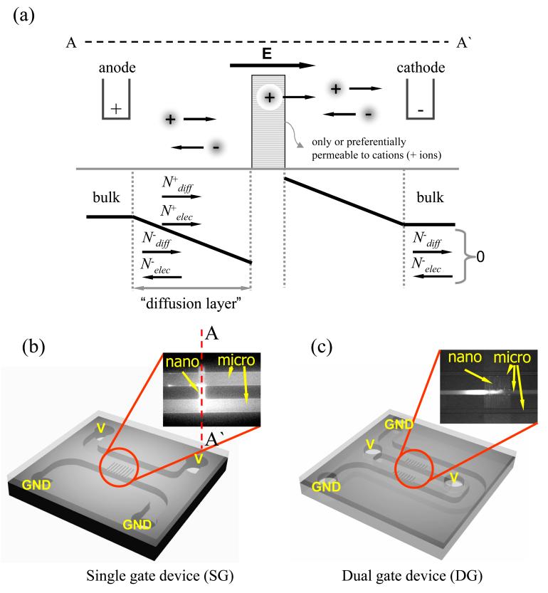
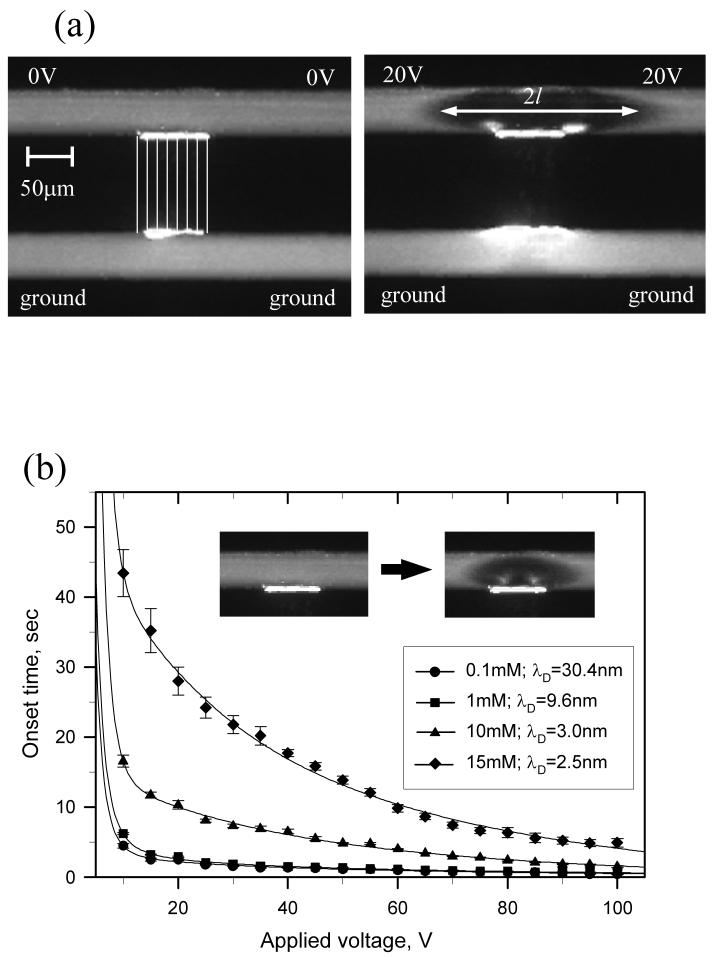
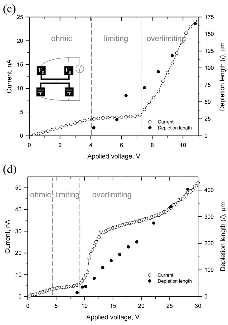
Classical theory of concentration polarization [8], which is normally used to explain concentration polarization near electrodes in electrochemistry, can also be useful to understand ion perm selectivity of nanofluidic channels. As shown in Fig. 1(a), the nanochannel array can be considered as a cation-selective membrane. On the anodic side, positive ions can enter the perm-selective nanochannel under a dc bias, while negative ions will be driven away from the nanochannel by the same dc bias. Conditions for overall electroneutrality require the concentrations of both cations and anions to decrease in the anodic side of the channel, creating a concentration gradient. Because of this concentration gradient, preferential cation transport through nanochannel is satisfied across the entire system, while maintaining net zero anion flux. The ion transport and concentration are limited in the boundary region (diffusion layer) near the membrane surface, and the distance is assumed to be about 10∼100 micrometer sitting between the bulk and the membrane. With a fixed diffusion length and bulk concentration, when we increase dc bias, the ion current will increase; therefore, the system will respond by decreasing the local ion concentration on the anodic side of the membrane (also known as the ion-depletion phenomenon). When the concentration approaches zero on the anodic side of the membrane, the system reaches a limiting current, above which no further increase in ion current is possible even with higher voltage applied to the system. However, in reality, significant overlimiting current can be observed in most perm-selective membranes, which is often associated with water dissociation at the vicinity of the membrane [8]. Rubinstein and co-workers [7], however, argued that water dissociation alone cannot explain the overlimiting current in its entirety, and suggested (theoretically) that there exists a strong convective mixing (EOF of the second kind, which destroys the concentration polarization), created by the “amplified” electrokinetic response of fluid layer right next to the membrane. In this case, the electrokinetic response would be amplified because of significantly lowered ion concentration near the nanochannel (membrane), therefore higher “local” zeta potential. Such strong flow patterns were observed in front of the charge gel [6] experimentally. It has to be noted that the concept of fixed “diffusion layer” length is ill defined, especially in a microchannel environment. Microfluidic systems can effectively suppress the convective mixing. Therefore, the diffusion layer could be extended all the way back to the reservoir. In our experiments, we have observed that the diffusion layer extended significantly (up to several millimeters), depending on the strength of external electric field and nonlinear electrokinetic mixing. Since the diffusion length critically determines the limiting current and other aspects of concentration polarization phenomena, the fixed diffusion distance assumed in the classical concentration polarization theory is no longer valid above the limiting-current condition. By imaging microbeads, charged and uncharged dye molecules within the nanochannel-microchannel junction with voltage configuration as shown in Figs. 1(b) and 1(c), along with current measurements, basic ion-depletion and ion-enrichment behavior were studied in a single gate (SG) device as shown in Fig. 2(a) (see supplementary video [9]). Figure 2(b) plots the time required for the initial depletion boundary to reach the opposite wall of the main microchannel, against buffer concentration and applied voltages. To significantly overlap the electrical double layer inside the nanochannel (40 nm deep), buffer concentration as low as ∼1 mM would be required. However, the graph clearly showed that the ion depletion was obtained at even higher than 10 mM buffer concentration, which corresponds to only ∼3 nm double layer thickness. At higher buffer ionic strength, however, it takes longer to reach concentration polarization. This clearly demonstrates that the concentration polarization (ion depletion) is a dynamic process, and the equilibrium Debye length λD alone cannot adequately describe the phenomena properly. Even when the Debye layer is not thick enough to cover the entire nanochannel depth, ion current through such channel could induce a small amount of additional counterions transported. Then, a weak concentration polarization can be induced, which will decrease ion concentration on the anodic side of the nanochannel. This will in turn lead to increased perm selectivity of nanochannel (via larger local Debye length), therefore eventually to even faster concentration polarization. Therefore, the concentration polarization process in nanochannel is indeed a positive feedback process, with ever decreasing local ion concentration and increasing perm selectivity (thicker local Debye layer thickness). It is also noteworthy that the electric field distribution will also be dependent on the concentration gradient in the system, and typical circuit-model analysis of microfluidic channel (assuming uniform ion concentration across the channel) is not valid in this situation.
Figure 1.
(color online). (a) Schematic diagram of ion concentration distribution front and back of perm-selective material which only let cations pass through. Ions in anodic side were depleted while they were enriched in cathodic side. Schematic configurations of (b) single gate device (SG) and (c) dual gate device (DG). GND is electrical ground.
Figure 2.
(a) The basic ion-enrichment and ion-depletion behavior in SG device. (b) The time required for the depletion boundary to reach opposite microchannel wall as functions of applied voltage and buffer concentrations. (c) Current sweep plot showing the limiting current and overlimiting current pattern. (d) With the influence of the irregular nonlinear flow merging and mixing, fluctuations can often be observed in the overlimiting region.
To study the correlation between the concentration polarization and nonlinear current behavior, negatively charged green fluorescent protein (GFP) molecules were injected into microchannels. As shown in Figs. 2(c) and 2(d), the current through nanochannels and the depletion length were measured simultaneously. In these experiments, the voltage applied across the nanochannel array was ramped up from 0 to 30 V over 900 sec. While the depletion length (l) is tracked by the minority carriers (GFP), it does not exactly represent the diffusion layer thickness δ, which is defined by the major carriers (sodium ions and phosphate ions). As shown in Fig. 2(c), the current profile can be divided into three regimes similar to ones reported in perm-selective membrane studies. Following the Ohmic regime, the onset of concentration polarization phenomenon concurs when limiting currents were measured. Moreover, if one further increases the applied potential, the depletion region can be further expended and the current can be extended beyond the limiting condition. Such nonlinear current behaviors were only observed when the current was measured across perm-selective nanofluidic arrays. The conductivity of the microchannel on the anodic side dropped significantly when we expended the depletion region.
It has to be noted that the current and the width of the depletion region, measured in Figs. 2(c) and 2(d), are not steady-state measurements. At a given fixed potential across the nanochannel array, the typical behavior is the deletion region keeps increasing while the conductivity keeps decreasing (mainly due to the ever-increasing depletion region) until the depletion region becomes unstable. Therefore, the onset of overlimiting current behavior can vary slightly from run to run, as shown in Figs. 2(c) and 2(d).
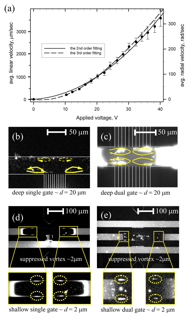
Because of the nonequilibrium concentration distribution inside and outside the ion-depletion zone, the Smoluchowski slip velocity (∼εξE/η) cannot be applied to our system. Rubinstein et al. derived the 2-dimensional nonequilibrium electro-osmotic slip velocity, under nonequilibrium bulk concentration condition [7]. Based on their calculation, the electro-osmotic velocity at a permselective solid or liquid interface is proportional to the square of applied voltage (|E|2) and the concentration gradient terms ((∂2c/∂x∂y)/(∂c/∂y), where y is a coordinate normal to the membrane (nanochannel) interface]. The nonequilibrium electro-osmotic slip velocity induced strong vortex at the perm-selective interface and we experimentally showed the vortex in SG and DG devices as shown in Fig. 3 (see supplementary videos [9]).
Figure 3.
(color online). (a) The linear velocity and angular velocity of the vortex as a function of applied voltage. (b) Fast vortex at steady state in SG device. (c) Four independent strong vortices in DG device. Suppressed vortices in (d) SSG and (e) SDG device. The size of the vortex was _2 μm, which was similar value of the microchannel depth. See supplementary videos [9].
The vortex flow speed was estimated to be usually over 1000 μm/sec , which is at least _∼10X higher than that of primary EOF under the same electrical potential as shown in Fig. 3(a). Recent theoretical studies show that the velocity of nonequilibrium EOF could be proportional to either the square [7,10] or cube [11] of applied voltage depending on the magnitude of applied electrical potentials. The corresponding Peclet number, which is the ratio of convection and diffusion, is over 100 and the experimental condition that we present here lies in a high Peclet number region. At the steady state, we can clearly observe the two counterrotating vortices beside the nanochannel, as shown in Fig. 3(b). In DG device, since the ions were depleted through both walls, the four independent vortices were formed in the four divided regions as shown in Fig. 3(c).
Such strong vortices would induce fast mixing and destroy any concentration gradient inside the ion-depletion region. Since the thickness of the diffusion layer scales as δ ∼ (xD/v)0.5 (assuming high Peclet number) [12], with the convective flow velocity v ∼ E2 (x: characteristic length of the system), one can conclude δ ∼ 1/E and the limiting current i’ = 2FDCo/δ ∼ E. The result complies with the experimental observation we have in Fig. 2(c). This observation is compatible with the idea that such a strong convection (in front of permselective membrane) is one of the mechanisms to explain overlimiting currents in the perm-selective membrane.
One can independently suppress the convective part of the phenomena by decreasing the microchannel thickness. A new shallow SG device (SSG) and a shallow DG device (SDG) had 2.0 micrometer depth (in contrast to 20 μm depth in the original SG and DG devices). As shown in Figs. 3(d) and 3(e), the sizes of the vortices in the dotted circle were approximately 2 μm, which corresponded to the depth of the microchannels. Because of those suppressed vortices, liquid mixing inside the depletion region was less efficient and thus the concentration gradient, which is the driving force of the perm-selective ion transport, was maintained more stably in this device. As a result, we can achieve significantly faster increase in fluorescence signal from the concentrated beads, demonstrating a faster preconcentration process. This result is also in line with experiments by Maletzki et al. [13], where agarose gel coating on a permselective membrane was shown to suppress the overlimiting current by eliminating electroconvections.
This study has several important implications in understanding nanochannel-membrane ion transport. In studying nanochannel ion or molecular transport, concentration changes in micro- or nanochannel interface would have significant impact both in field and concentration distribution, and cannot be simply ignored as an “edge effect.” Even at moderate buffer ionic strength, strong concentration polarization could be triggered, especially under the dc field. Once generated, concentration polarization near nanochannel (membrane) would lead to strong, nonlinear electrokinetic flow, which in turn would affect ion or molecular transport through the nanochannel. While theoretically challenging, such a coupled nature of this problem should be considered or checked in future studies involving perm-selective nanochannels or nanomembranes. This work was mainly supported by NIH Grants (No. EB005743 and No. CA119402) and partially supported by NSF CAREER (No. CTS-0347348), NIH CDP Center Grant (No. GM068762), Samsung Electro Mechanics and KOSEF.
Supplementary Material
REFERENCES
- [1].Mao P, Han J. Lab Chip. 2005;5:837. doi: 10.1039/b502809d. [DOI] [PubMed] [Google Scholar]
- [2].Han J, Craighead HG. Science. 2000;288:1026. doi: 10.1126/science.288.5468.1026. [DOI] [PubMed] [Google Scholar]; Huang LR, et al. Nat. Biotechnol. 2002;20:1048. doi: 10.1038/nbt733. [DOI] [PubMed] [Google Scholar]; Saleh OA, Sohn LL. Nano Lett. 2003;3:37. [Google Scholar]; Karnik R, et al. Nano Lett. 2005;5:1638. doi: 10.1021/nl050966e. [DOI] [PubMed] [Google Scholar]; Fu J, et al. Nature Nanotechnology. 2007;2:121. doi: 10.1038/nnano.2006.206. [DOI] [PMC free article] [PubMed] [Google Scholar]
- [3].Wang Y-C, Stevens AL, Han J. Anal. Chem. 2005;77:4293. doi: 10.1021/ac050321z. [DOI] [PubMed] [Google Scholar]
- [4].Pu Q, et al. Nano Lett. 2004;4:1099. [Google Scholar]; Plecis A, Schoch RB, Renaud P. Nano Lett. 2005;5:1147. doi: 10.1021/nl050265h. [DOI] [PubMed] [Google Scholar]; Schoch RB, Renaud P. Appl. Phys. Lett. 2005;86:253111. [Google Scholar]; Stein D, Kruithof M, Dekker C. Phys. Rev. Lett. 2004;93:035901. doi: 10.1103/PhysRevLett.93.035901. [DOI] [PubMed] [Google Scholar]
- [5].Squires TM, Bazant MZ. J. Fluid Mech. 2004;509:217. [Google Scholar]
- [6].Mishchuk NA, Takhistov PV. Colloids Surf. A. 1995;95:119. [Google Scholar]; Ben Y, Chang H-C. J. Fluid Mech. 2002;461:229. [Google Scholar]; Leinweber FC, Tallarek U. Langmuir. 2004;20(11) doi: 10.1021/la048408n. [DOI] [PubMed] [Google Scholar]
- [7].Rubinstein I, Shtilman L. J. Chem. Soc., Faraday Trans. 2. 1979;75:231. [Google Scholar]; Rubinstein I, Zaltzman B. Phys. Rev. E. 2000;62:2238. doi: 10.1103/physreve.62.2238. [DOI] [PubMed] [Google Scholar]; Rubinstein I, Zaltzman B, Lerman I. Phys. Rev. E. 2005;72:011505. doi: 10.1103/PhysRevE.72.011505. [DOI] [PubMed] [Google Scholar]
- [8].Probstein RF. Physicochemical Hydrodynamics: An Introduction. Wiley-Interscience; New York: 1994. [Google Scholar]
- [9]. See EPAPS Document No. E-PRLTAO-99-041729 for supplementary videos. For more information on EPAPS, see http://www.aip.org/pubservs/epaps.html.
- [10].Ben Y, et al. J. Colloid Interface Sci. 2004;276:483. doi: 10.1016/j.jcis.2004.04.004. [DOI] [PubMed] [Google Scholar]
- [11].Zaltzman B, Rubinstein I. J. Fluid Mech. 2007;579:173. [Google Scholar]
- [12].Mishchuk NA, Dukhin SS. Electrophoresis. 2002;23:2012. doi: 10.1002/1522-2683(200207)23:13<2012::AID-ELPS2012>3.0.CO;2-Y. [DOI] [PubMed] [Google Scholar]
- [13].Maletzki F, Rossler HW, Staude E. J. Membr. Sci. 1992;71:105. [Google Scholar]
Associated Data
This section collects any data citations, data availability statements, or supplementary materials included in this article.


