

Abstract
Here we describe a simple method to prepare voltammetric microelectrodes using tungsten wires as a substrate. Tungsten wires have high tensile modulus and enable the fabrication of electrodes that have small dimensions overall while retaining rigidity. In this work, 125 μm tungsten wires with a conical tip were employed. For the preparation of gold or platinum ultramicroelectrodes, commercial tungsten microelectrodes, completely insulated except at the tip, were used as substrates. Following removal of oxides from the exposed tungsten, platinum or gold was electroplated yielding surfaces with an electroactive area of between 1×10⁻⁶ cm2 to 2×10⁻⁶ cm2. Carbon surfaces on the etched tip of tungsten microwires were prepared by coating with photoresist followed by pyrolysis. The entire electrode was then insulated with Epoxylite except the tip yielding an exposed carbon surface with an area of around 4×10⁻⁶ cm2 to 6×10⁻⁶ cm2. All three types of ultramicroelectrodes fabricated on the tungsten wire had similar electrochemical behavior to electrodes fabricated from wires or fibers insulated with glass tubes.
Introduction
Ultramicroelectrodes have clearly demonstrated advantages in a variety of applications. They can be used to probe chemistry in small volumes, to examine chemistry that occurs on a submicrosecond time scale, and to examine electrochemical reactions in solutions of very high resistance1. These properties have made microelectrodes particularly useful for applications in biological systems,2 but also in other applications such as chromatography scanning-probe microscopy3, 4, and photoelectrochmical processes5. The most common substrates for voltammetric ultramicroelectrodes are platinum, gold, and carbon. Microscopic platinum and gold wires and carbon fibers are all commercially available, and have been used to prepare ultramicroelectrodes. Typically, these materials are sealed into sealed soft glass capillaries6 leaving a disk or cylindrical section of the conductor exposed. Epoxy-resin can be used to seal any cracks between the fiber and the glass insulation6. Diamond microelectrodes have been constructed by growing the diamond layer on etched stainless steel or tungsten microwires and insulating the shaft of the electrode7, 8 to form a conical microelectrode.
Predating voltammetric microelectrodes are microelectrodes used by electrophysiologists for voltage sensing. For example, conical microelectrodes formed from tungsten wires with an etched tip and with lacquer9 or glass10 insulation can measure the electrical activity of a single neuron. They are commercially available as tungsten electrodes insulated with paralene11 or epoxy resin12–14, with an exposed tip formed by removing the insulation with a laser. These electrodes are unsuitable for voltammetric measurement because of the corrosion properties15 of tungsten. The oxides produce large background currents that interfere with faradaic currents from species in solution. However, they have several useful physical attributes. Tungsten microelectrodes have a higher rigidity than glass insulated microelectrodes but can be bent without damaging the insulation. The rigidity of a material can be quantified by the tensile modulus, which is the quotient of the tensile stress over the tensile strain. With a tensile modulus of 411 GPa16 compared to 170 gPa16 for platinum and 78.5 GPa16 for gold, small tungsten wires are sufficiently stiff that they can be used without further support. Furthermore, tungsten wires are less brittle than carbon and glass rods of similar dimensions. Thus, in addition to small a sensing area, the overall diameter of tungsten-based electrodes coated with an insulator can be much smaller than microelectrodes that use glass tubes as the insulating material.
In this work we describe electrodes that have the physical properties of tungsten microwires and voltammetric properties of the commonly used electrode materials platinum, gold, and carbon. The electrodes were prepared by coating the conical tip of 125 μm-diameter tungsten microwires with the desired electrode material. To prepare gold and platinum electrodes, commercial electrophysiological electrodes, insulated tungsten wires with an exposed conical tip, were electroplated with the desired metal. For carbon tips, a technique developed by McCreery and coworkers was adapted which involves coating a substrate with photoresist followed by pyrolysis17, 18. The pyrolyzed photoresist film (PPF) has similar electrochemical properties to glassy carbon. Electrodes produced this way open a new range of applications because of their simultaneous flexibility and rigidity. They are freely bendable and have micrometer dimensions (125 μm) over the whole length of the electrode.
Experimental section
Preparation of tungsten conical tips
For the preparation of gold and platinum electrodes, the substrate was an epoxy-insulated tungsten microelectrode (AM-systems, 0.005″, 5 MΩ, 8 degree). The exposed tips were cleaned for 10 seconds in hydrofluoric acid (48%, Sigma-Aldrich, St. Louis, MO) then electrolyzed for 30 sec at 50 °C in electrocleaning solution (Electrocleaner, Shor Int., Mt. Vernon, NY) at −5 V vs. a platinum or gold counter electrode.
Because the carbon deposition employs pyrolysis, the substrate for these microelectrodes was an uninsulated tungsten wire (99.95 %, diameter 0.125mm, length 75mm, Advent Research Material, Eynsham, England). A conical tip was prepared by etching in a saturated sodium nitrite solution containing 1M NaOH at an AC potential of 10V (60Hz). The counter electrode was a stainless steel coil. The wires were lowered slowly into the etching solution until gas evolution was observed and raised again when the gas evolution stopped. After etching, the tungsten wires were cleaned with hydrofluoric acid and electrocleaning solution as described above.
Electrodeposition of platinum and gold
After the tungsten tip was cleaned, the electrode was rinsed with doubly distilled water (Megapure system, Corning, NY) and transferred into a plating solution. For platinum it was Platinum TP PTU, 240451GL (Technic Inc, Cranston, RI). Platinum was plated for 5 sec at −0.5 V vs a platinum counter electrode at 50 °C. After plating, the electrode was rinsed with double distilled water and then used or stored in ethanol.
Gold microelectrodes were formed similarly as described for platinum microelectrodes. For the cleaning and plating processes a gold counter electrode was used instead of platinum to minimize contamination. The plating was done at in gold plating solution (Gold plating solution 24k Royale, Shor Int., Mt. Vernon, NY) for 30 sec at −1V vs a gold counter electrode. The electrodes were also stored in ethanol.
Carbon deposition
Multiple (up to 15) cleaned and etched tungsten wires were dipped 3 times into photoresist (AZ P4330-RS, Clariant, Sommerville, NJ) in 5 min intervals with a Burleigh micromanipulator (Burleigh Inchworm, CE-1000, fishers, NY). The electrodes were pulled out of the photoresist at a speed of 2mm/min. The electrodes were then transferred into a furnace oven (Lindberg Blue, TF55035A-1) fitted with a quartz tube. Forming gas (95% nitrogen, 5% hydrogen, National Specialty Gases) flowed though the tube furnace at an approximate rate of 100 ml/min. The tube was purged for 20 min at room temperature and then the temperature was increased linearly for 100 min to 1000 °C, held at 1000 °C for 2 hours, and then cooled to room temperature. To insulate the electrodes, the tip was masked with paraffin wax (mp 53–57, Sigma-Aldrich). Paraffin wax was melted in a heating coil that was positioned under a stereoscope. The electrode was then carefully inserted into the wax with a micromanipulator to cover the desired surface area, and then the electrode was pulled back leaving a wax layer at the tip. The masked wires were then dipped 3 times into Epoxylite insulation (#6001, Altanta Varnish compounds, St. Louis, MO) in 5 min intervals with a Burleigh micromanipulator at a speed of 2mm/min. The electrodes were cured standing with the tip up at 200 °C for 30 min. Excess wax was removed with turpentine (Klean Strip, W.M. Barr & Co Inc, Memphis, TN). Before use the electrodes were soaked in 2-propanol purified with Norit A activated carbon (ICN, Costa Mesa, CA) for at least 20 min19.
Glass encased microelectrodes
For comparison, conventional microelectrodes were prepared. A short length (2 cm) platinum or gold wire (99.99%, 25 μm diameter, Goodfellow Cambridge Limited, England) was mounted on a wire with silver epoxy (H2O-PFC, EPO-TEK, Billerica, MA) and inserted into a soft glass capillary so that the tip of the microwire extended beyond the capillary. The hookup wire was attached to the back of the capillary with Torr Seal (Varian Vacuum Technologies). The tip of the electrode was then melted with a heating coil, which yielded a tight glass seal around the gold wire. The electrode was polished subsequently with alumina slurries of 1 μm, 0.3 μm and 0.05 μm size. Before each experiment the polishing step with 0.05 μm alumina slurry was repeated and the electrode was rinsed with doubly distilled water (Megapure system, Corning, NY).
Carbon-fiber microelectrodes were fabricated as previously described20 with P-55 carbon fibers (Thornel, Amoco Corp., Greenville, SC). A single fiber was aspirated into a glass capillary and pulled on a micropipette puller (Narashige, Tokyo, Japan). The fiber was sealed into the capillary with epoxy resin (Epon 828 with 14% m-phenlylenediamine by weight, Miller Stephenson Chemical Co., Danbury, CT). After curing the epoxy, the electrodes were polished at a 45° angle on a diamond embedded polishing wheel (Sutter Instruments), resulting in an elliptical surface of approximately 10−6 cm. The capillaries of the microelectrodes were backfilled with electrolyte solution (4 M potassium acetate, 150 mM potassium chloride), and wires were inserted into the capillary for electrical contact. Before use electrodes were soaked in isopropanol purified with Norit A activated carbon (ICN, Costa Mesa, CA) for at least 20 minutes.
Voltammetric characterization
Cyclic voltammograms were acquired with the EI-400 potentiostat (Ensman Instrumentation, Bloomington, IN), locally constructed hardware, and software written in LabVIEW (National Instruments, Austin, TX) that has been described previously21. The electrochemical cell was placed inside a grounded Faraday cage to minimize electrical noise. For background-subtracted cyclic voltammograms the electrode was positioned at the outlet of a 6-port rotary valve. The loop injector was mounted on an actuator (Rheodyne model 5041 valve and 5701 actuator) that was controlled by a 12-V DC solenoid valve kit (Rheodyne, Rohnert Park, CA). This introduced the analyte to the electrode surface. Solution was driven with a syringe infusion pump (2 cm/s, Harvard Apparatus Model 22, Holliston, MA) through the valve and the electrochemical cell. For all experiments a Ag-AgCl reference electrode (Bioanalytical Systems, West Lafayette, ID) was used. Fast-scan cyclic voltammograms were low-pass filtered in the software at 5 kHz, slow scan measurements were filtered with a built-in second order low-pass hardware filter at 1 Hz. Steady state currents obtained from slow scan measurements were used to calculate the electroactive area of the electrodes.
Chemicals
Aqueous solutions employed doubly distilled water (Megapure system, Corning, NY). Solutions were degassed for 15 min with nitrogen before use. All chemicals for electrochemical analysis were purchased form Sigma-Aldrich (St. Louis, MO) and used as received. Solutions of potassium hexacyanoferrate(III) were prepared in 1M potassium chloride. Solutions of ferrocenecarboxylic acid were prepared in 0.01M phosphate buffer (pH 7.0) with the addition of 1M potassium chloride. Background scans were performed in 0.5 M sulfuric acid, 0.1 M perchloric acid and in TRIS buffer solution which was adjusted to pH 7.4 containing 15 mM TRIS, 140 mM NaCl, 3.25 mM KCl, 1.2 CaCl2, 1.25 mM NaH2PO4, 1.2 mM MgCl2 and 2.0 mM Na2SO4.
Results and Discussion
Fabrication Considerations
In the fabrication process, three aspects are central to obtain a functional microelectrode. The first issue is the resistance between the tungsten substrate and the deposited metal or carbon layer. Tungsten metal forms a passivated oxide layer when exposed to oxygen15, and tungsten oxide is formed during the electrochemical etching procedure. It has been shown that this oxide layer causes instabilities in the tunneling current when used as an STM tip22. In our case the oxide layer will add to the resistance between the tungsten and the deposited surface. However, concentrated hydrofluoric acid dissolves surface tungsten oxides22–24 and thus minimizes the resistance.
Secondly it is important to achieve a relatively smooth, complete, and durable deposition of the electrode surface. The noble-metal plating solutions used in this study include complexing agents that buffer the free concentration of metal ions and promote formation of a smooth surface. However, plating variables such as temperature, plating time, and plating potential have to be carefully optimized. Otherwise dendritic growth or incomplete surface covering will occur. The conditions described here lead to a smooth platinum surface as can be seen in figure 1a. However, the gold layer is considerably rougher with the conditions employed (figure 1b). The deposition conditions selected for gold were a compromise. At higher plating potentials even rougher surface were formed due to dendritic growth while at a lower potential plating was often incomplete. Dip-coating with photoresist, the carbon precursor, required removal at a constant but slow speed to achieve complete coverage. The pyrolyzed photoresist films have been reported to have very smooth surfaces on silicon wafers18. SEM images of photoresist-coated tungsten wires indicate a similar morphology on the etched tungsten (Figure 1c).
Figure 1.
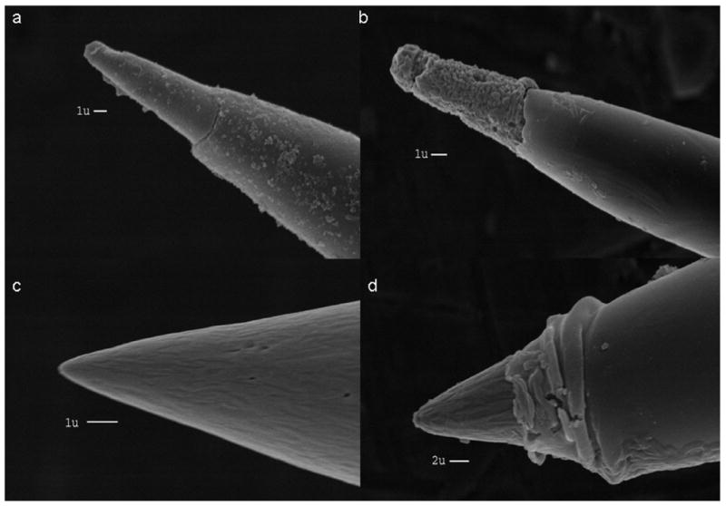
SEM images of conical microelectrodes: (a) Platinum plated electrode (b) Gold plated electrode (c) Etched tungsten wire coated with PPF (d) PPF electrode insulated with Epoxylite
The final requirement for a functional microelectrode is an intact insulation layer. Both types of electrode insulation (the commercially available electrodes and Epoxylite insulated electrodes) are stable when used in aqueous solution over the time course of several days. Exposure to alcohols or non oxidizing concentrated acids for several hours did not affect the insulation quality measured by AC impedance of the electrode. According to the specifications25 the Epoxylite insulation is stable in alkali as well as many organic solvents, however, these conditions were not tested in this study. Both types of insulation were sufficiently flexible to remain intact during vibration of the tungsten wire. Direct physical impact, especially close to the exposed tip, or permanently bending the wire can damage the insulation. As can be seen in figure 1d the Epoxylite insulation forms a slight bulge on the shaft of the electrode. This originates from excess Epoxylite that accumulated around the wax mask. During curing the insulation flows back and hardens to function as a reinforcement of the insulation close to the electrode tip. The size of the exposed area at the PPF electrodes varies according to the size of the wax mask applied to the electrode tip.
Electrochemical behavior of platinum plated electrodes
To test the electrochemical performance of the conical ultramicroelectrodes we compared cyclic voltammetric responses of the plated electrodes with the responses at analogous glass encased electrodes. For the platinum, gold and carbon electrodes cyclic voltammograms in background solution were taken to compare oxidation and reduction of the electrode material as well to observe hydrogen and oxygen adsorption and evolution. To characterize faradaic reactions, the reduction of ferricyanide and the oxidation of the water soluble ferrocene compound, ferrocenecarboxylic acid, were used. For these analytes both background subtracted fast-scan cyclic voltammograms as well as slow scan voltammograms were recorded.
Figure 2b shows the cyclic voltammogram of a platinum-plated electrode in 0.5 M sulfuric acid recorded at 10 V/s. This background response is identical with a cyclic voltammogram recorded at a microelectrode prepared from a platinum wire (figure 2a) and those reported in the literature26. The peaks in the hydrogen region are well developed27. The presence of clearly distinct peaks for adsorption and desorption of hydrogen shows that the surface of the plated electrode is relatively clean and useful for electroanalysis28. Both ferricyanide and ferrocenecarboxylic acid show similar voltammetric responses at slow and fast scan rates at the two platinum surfaces. The peak separation (ΔEp) for both analytes indicates similar electron transfer kinetics. Slow scan cyclic voltammograms show the expected sigmoidal shape and have a similar half-wave potential, E1/2. During this study, 30 electrodes were plated with platinum, and approximately 90 % showed well behaved electrochemistry similar to that shown in Figure 2. For the remaining 10% the slow scan voltammograms exhibited resistive effects characterized by a severely ramping current. This was attributed to incomplete metal coverage of the underlying tungsten or a defect in the insulation. In these cases, replating often led to improved performance. The electrodes were used in several experiments and were cleaned between experiments by cycling to positive potentials29.
Figure 2.
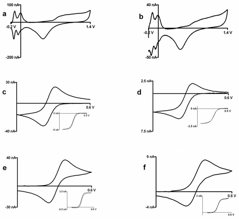
Cyclic voltammograms at tungsten microelectrodes; left panel: Glass encased platinum disk electrodes, right panel: Platinum plated tungsten electrodes (a,b) 0.5 M sulfuric acid at 10 V/s (c,d) Background subtracted cyclic voltammogram at 100 V/s for injection of 1 mM ferricyanide in 1M KCl; insets: cyclic voltammogram for 1mM ferricyanide in 1M KCl at 10 mV/sec, c) ΔEp= 73 mV, E1/2 = 0.254 V vs. Ag/AgCl, d) ΔEp= 83 mV, E1/2 = 0.265 V vs. Ag/AgCl (e,f) Background subtracted cyclic voltammogram at 100 V/s for injection of 1 mM ferrocenedicarboxylic acid in 0.01 M phosphate buffer with 1M KCl; insets: cyclic voltammogram for 1mm ferrocenedicarboxylic acid in 0.01 M phosphate buffer with 1M KCl at 10 mV/sec, e) ΔEp= 84 mV, E1/2 = 0.317 V vs. Ag/AgCl, f) ΔEp= 89 mV, E1/2 = 0.323 V vs. Ag/AgCl
Electrochemical behavior of gold plated electrodes
The cyclic voltammogram obtained at gold plated electrodes in perchloric acid shows clearly defined oxidation and reduction peaks that are comparable to the cyclic voltammograms obtained at glass encased gold microelectrodes (figure 3a). The responses to the analytes shown in figure 3c–f are similar to the observation made at platinum electrodes regarding electron transfer, diffusion, and surface coverage as can be seen in similar ΔEp values for fast-scan measurements and similar E1/2 values at for slow-scans. However, cleanliness and complete surface coverage is a harder to achieve by gold plating compared to platinum plating as indicated by the rougher coating in figure 1c. Alternative procedures like vacuum deposition or sputtering of gold layers may result in smoother surfaces, but the electroplating does not require expensive equipment or clean room facilities. Twenty electrodes were plated with gold layer in this study. The success rate for gold electrodes was around 70%, lower than for platinum plating. As with platinum, gold plated electrodes could be recycled by stripping of the gold layer followed by replating. Successfully plated electrodes can be used over the course of several experiments.
Figure 3.

Cyclic voltammograms at gold microelectrodes; left panel: glass encased platinum disk electrodes, right panel: gold plated tungsten electrodes (a,b) 0.1 M perchloric acid at 0.1V/s (c,d) Background subtracted cyclic voltammogram at 100 V/s for injection of 1mM ferricyanide in 1M KCl; insets: cyclc voltammogram for 1mM ferricyanide in 1M KCl at 10 mV/sec, c) ΔEp= 120 mV, E1/2 = 0.277 V vs. Ag/AgCl, d) ΔEp= 114 mV, E1/2 = 0.259 V vs. Ag/AgCl (e,f) Background subtracted cyclic voltammogram at 100 V/s for injection of 1 mM ferrocenecarboxylic acid in 0.01 M phosphate buffer with 1M KCl; insets: cyclc voltammogram for 1 mM ferrocenecarboxylic acid in 0.01 M phosphate buffer with 1 M KCl at 10 mV/sec, e) ΔEp= 80 mV, E1/2 = 0.316 V vs. Ag/AgCl, f) ΔEp= 89 mV, E1/2 = 0.319 V vs. Ag/AgCl
Electrochemical behavior of pyrolyzed photoresist film (PPF) electrodes
For large electrodes prepared from pyrolyzed photoresist films (PPF), the electrochemical properties are similar to glassy carbon. The electrochemical properties of PPF films have been described in the literature17, 18. The first panel in figure 4 a,b shows fast scan background voltammograms in physiological TRIS Buffer (ph 7.4) as reported earlier30 and slow-scan cyclic voltammograms recorded in sulfuric acid. The slow-scan cyclic voltammograms show no significant oxidation or reduction features except for oxygen formation as expected. At neutral pH and fast-scan rates, carbon-fiber microelectrodes exhibit features in the cyclic voltammogram due to change in oxidation state of oxygen-containing functional groups on the surface. These can be observed on the anodic scan around 0.2V vs Ag/AgCl and on the cathodic scan at −0.2V vs Ag/AgCl. Both the glass encased carbon-fiber microelectrode as well as the PPF- microelectrode show these waves.
Figure 4.

Cyclic voltammograms at carbon microelectrodes; left panel: glass encased carbon-fiber disk electrodes, right panel: PPF microelectrodes (a,b) TRIS buffer (pH 7.4); insets : sulfuric acid at 0.1 V/s (c,d), c) ΔEp= 712 mV, E1/2 = 0.219 V vs. Ag/AgCl, d) ΔEp= 745 mV, E1/2= 0.205 V vs. Ag/AgCl Background subtracted cyclic voltammogram at 100 V/s for injection of 1mM ferricyanide in 1 M KCl; insets: cyclc voltammogram for 1 mM ferricyanide in 1 M KCl at 40 mV/sec (e,f) Background subtracted cyclic voltammogram at 100 V/s for injection of 1 mM ferrocenecarboxylic acid in 0.01 M phosphate buffer with 1 M KCl; insets: cyclic voltammogramfor 1mM ferrocenecarboxylic acid in 0.01 M phosphate buffer with 1 M KCl at 10 mV/sec, e) ΔEp= 106 mV, E1/2 = 0.334 V vs. Ag/AgCl, f) ΔEp= 110 mV, E1/2 = 0.327 V vs. Ag/AgCl
The shape of the voltammogram for ferricyanide at the PPF-electrode is similar to that obtained at carbon-fiber electrodes. Electron transfer at carbon electrodes for ferricyanide has been shown to be relatively slow31, 32 at untreated carbon electrodes. Studies have shown that these slow kinetics might be due to surface contaminants33, the microstructure of carbon, or surface oxidation34. Overall the responses for the analytes ferricyanide and ferrocenecarboxlylic acid at PPF electrodes and carbon fiber microelectrodes show similar peak separation and half-wave potentials indicating similar electron transfer kinetics. Twenty-five carbon-deposited electrodes were examined in this study. All electrodes with a full coverage of pyrolyzed photoresist as observed under a stereoscope resulted in functional electrodes. However, about 35% of the tungsten wires did not show complete coverage of the tungsten rod, especially at the tip, and these exhibited highly resistive behavior or were not functional.
Surface area of conical electrodes
The electrode area was determined from the limiting current obtained from the slow-scan cyclic voltammograms in figure 2–4 d and f. For a disk electrode the steady-state current can be calculated as26:
| (1) |
where n is the number of electron transferred, F is Faraday’s constant, D is the diffusion coefficient of the analyte, c is the bulk concentration of the analyte, and r is the radius of the disk. The steady-state current at finite conical microelectrodes can be approximated by 35 :
| (2) |
where is the steady state current of a disk electrode of equivalent radius (r), RG is the ratio of the radius of the base of the insulating sheath over the radius of the cone, A, B, C, and D are numerical constants which depend on the aspect ratio, H, of the cone. H is defined as the height of the cone divided by the radius. Equation (2) can be rewritten to yield the radius of the cone.
| (3) |
The insulating sheath is very thin, so the value for RG was taken as 1.1.
The area for all the platinum- and gold-plated electrodes was quite similar because it was primarily determined by the amount of uninsulated tungsten on the commercially obtained electrode substrates. H for these electrodes was determined to be 4 (figure 1a), however values for A, B, C, and D for aspect ratios higher than 3 have not been reported. Therefore, for platinum and gold electrodes the base radius was calculated with the term in brackets in equation (3) extrapolated from theoretical working curves35 to be equal to 3.25 for H = 4 and RG = 1.1. With the corresponding height calculated from the aspect ratio H, the surface area were calculated. For platinum conical electrodes the area was 1.2 ± 0.4 × 10⁻⁶ cm2 and for gold the area was 1.4 ± 0.4 × 10⁻⁶ cm2 (errors given as standard deviations). The geometrical area, estimated from figure 1a, is 1×10⁻⁶ cm2 in reasonable agreement with the electrochemical data. The gold-surface area was also estimated by calculating the amount of charge consumed by reduction of the gold oxide layer in perchloric acid (figure 3b) using a reported value of 400μC/cm2 36. This method led to surface areas almost twice as large, presumably reflecting the surface roughness.
The current amplitudes from the PPF electrodes varied more than those of the platinum and gold electrodes, because the exposed area depends on the wax mask applied to the tip, an imprecise procedure. To calculate the electrochemical area, an H of 3 (figure 1c) was used and the values for the constants A, B, C, and D were taken from the literature 35. Areas of these electrodes varied from 1×10⁻⁶ cm2 to 10×10−6 cm2, with the majority in the range of 4×10⁻⁶ cm2 to 6×10⁻⁶ cm2.
Summary
Intact films of platinum, gold and carbon were deposited onto tungsten mirowires to obtain microelectrodes that are functional for voltammetric studies. These microelectrodes show similar electrochemical responses for the reduction of ferricyanide as well as for the oxidation of ferrocenecarboxylic acid as ultramicroelectrodes formed from pure metals. The formation and reduction of surface oxides for the deposited materials are also similar to the glass encased analogues. The microwires retain the flexibility and rigidity of tungsten microelectrodes with the electrochemical properties of platinum gold and carbon. The micrometer dimensions of the electroactive areas offer the possibility to arrange the electrodes in closely spaced arrays which is not possible with glass encased electrodes.
Acknowledgments
This research was supported by NIH (NS15841). Discussions with Richard McCreery concerning PPF deposition are acknowledged.
References
- 1.Wightman RM, Wipf DO. In: Electroanalytical Chemistry, A series of advances. Bard JA, editor. Vol. 15. Marcel Dekker, INC; New York and Basel: 1989. p. 267. [Google Scholar]
- 2.Wightman RM. Science. 2006;311:1570–1574. doi: 10.1126/science.1120027. [DOI] [PubMed] [Google Scholar]
- 3.Holder MN, Gardner CE, Macpherson JV, Unwin PR. J Electroanal Chem y. 2005;585:8–18. [Google Scholar]
- 4.Walsh DA, Fernandez JL, Mauzeroll J, Bard AJ. Anal Chem. 2005;77:5182–5188. doi: 10.1021/ac0505122. [DOI] [PubMed] [Google Scholar]
- 5.Fan FF. In: Electrogenerated Chemoluminescence. Bard AJ, editor. Marcel Dekker; New York: 2004. p. 23. [Google Scholar]
- 6.Zoski CG. Electroanalysis. 2002;14:1041–1051. [Google Scholar]
- 7.Park J, Show Y, Quaiserova V, Galligan JJ, Fink GD, Swain GM. J Electroanal Chem. 2005;583:56–68. [Google Scholar]
- 8.Cvacka J, Quaiserova V, Park J, Show Y, Muck A, Swain GM. Anal Chem. 2003;75:2678–2687. doi: 10.1021/ac030024z. [DOI] [PubMed] [Google Scholar]
- 9.Hubel DH. Science. 1957;125:549–550. doi: 10.1126/science.125.3247.549. [DOI] [PubMed] [Google Scholar]
- 10.Levivk WR. Med Biol Eng. 1971;10:510–515. doi: 10.1007/BF02474199. [DOI] [PubMed] [Google Scholar]
- 11.Loeb GE, Bak MJ, Salcman M, Schmidt EM. Ieee Transactions on Biomedical Engineering. 1977;24:121–128. doi: 10.1109/TBME.1977.326115. [DOI] [PubMed] [Google Scholar]
- 12.Freeman JA. Electroencephalography and Clinical Neurophysiology. 1969;26:623. doi: 10.1016/0013-4694(69)90011-x. [DOI] [PubMed] [Google Scholar]
- 13.Ciancone MT, Rebec GV. J Neurosci Methods. 1989;27:77–79. doi: 10.1016/0165-0270(89)90053-8. [DOI] [PubMed] [Google Scholar]
- 14.Verhagen JV, Gabbott PL, Rolls ET. J Neurosci Methods. 2003;123:215–217. doi: 10.1016/s0165-0270(02)00365-5. [DOI] [PubMed] [Google Scholar]
- 15.Lillard RS, Kanner GS, Butt DP. J Electrochem Soc. 1998;145:2718–2725. [Google Scholar]
- 16.Goodfellow Cambridge Limited, Technical Data, www.goodfellow.com.
- 17.Ranganathan S, McCreery R, Majji SM, Madou M. J Electrochem Soc. 2000;147:277–282. [Google Scholar]
- 18.Ranganathan S, McCreery RL. Anal Chem. 2001;73:893–900. doi: 10.1021/ac0007534. [DOI] [PubMed] [Google Scholar]
- 19.Bath BD, Michael DJ, Trafton BJ, Joseph JD, Runnels PL, Wightman RM. Anal Chem. 2000;72:5994–6002. doi: 10.1021/ac000849y. [DOI] [PubMed] [Google Scholar]
- 20.Kawagoe KT, Zimmerman JB, Wightman RM. J Neurosci Methods. 1993;48:225–240. doi: 10.1016/0165-0270(93)90094-8. [DOI] [PubMed] [Google Scholar]
- 21.Michael DJ, Joseph JD, Kilpatrick MR, Travis ER, Wightman RM. Anal Chem. 1999;71:3941–3947. doi: 10.1021/ac990491+. [DOI] [PubMed] [Google Scholar]
- 22.Hockett LA, Creager SE. Rev Sci Instr. 1993;64:263–264. [Google Scholar]
- 23.Paparazzo E, Moretto L, Selci S, Righini M, Farne I. Vacuum. 1999;52:421–426. [Google Scholar]
- 24.Ottaviano L, Lozzi L, Santucci S. Re Sci Instr. 2003;74:3368–3378. [Google Scholar]
- 25.The PD George Company, A. V. C. Technical Bulletin, Epoxylite Insulator #6001.
- 26.Bard AJ, Faulkner LR. Electrochemical Methods. 2. Wiley; New York: 2001. p. 570. [Google Scholar]
- 27.Tu WY, Liu WJ, Cha CS, Wu BL. Electrochim Acta. 1998;43:3731–3739. [Google Scholar]
- 28.Suzuki H, Hirakawa T, Sasaki S, Karube I. Anal Chim Acta. 1999;387:103–112. [Google Scholar]
- 29.Manica DP, Mitsumori Y, Ewing AG. Anal Chem. 2003;75:4572–4577. doi: 10.1021/ac034235f. [DOI] [PubMed] [Google Scholar]
- 30.Hermans A, Seipel AT, Miller CE, Wightman RM. Langmuir. 2006;22:1964–1969. doi: 10.1021/la053032e. [DOI] [PMC free article] [PubMed] [Google Scholar]
- 31.Deakin MR, Stutts KJ, Wightman RM. J Electroanal Chem. 1985;182:113–122. [Google Scholar]
- 32.Cline KK, Mcdermott MT, Mccreery RL. J Phys Chem. 1994;98:5314–5319. [Google Scholar]
- 33.Kiema GK, Aktay M, McDermott MT. J Electroanal Chem. 2003;540:7–15. [Google Scholar]
- 34.Ji XB, Banks CE, Crossley A, Compton RG. Chemphyschem. 2006;7:1337–1344. doi: 10.1002/cphc.200600098. [DOI] [PubMed] [Google Scholar]
- 35.Zoski CG, Mirkin MV. Anal Chem. 2002;74:1986–1992. doi: 10.1021/ac015669i. [DOI] [PubMed] [Google Scholar]
- 36.El-Deab MS, Okajima T, Ohsaka T. J Electrochem Soc. 2003;150:A851–A857. [Google Scholar]