

Abstract
The integration of semi-porous membranes into PDMS microfluidic devices is useful for mass transport control. Several methods such as plasma oxidation and manual application of PDMS prepolymer exist to sandwich such membranes into simple channel structures, but these methods are difficult to implement with reliable sealing and no leakage or clogging for devices with intricate channel features. This paper describes a simple but robust strategy to bond semi-porous polyester and polycarbonate membranes between layers of PDMS microchannel structures effectively without channel clogging. A thin layer of PDMS prepolymer, spin-coated on a glass slide, is transferred to PDMS substrates with channel features as well as to the edges of the semi-porous membrane by stamping. This thin PDMS prepolymer serves as “mortar” to strongly bond the two PDMS layers and seal off the crevices generated from the thickness of the membranes. This bonding method enabled the fabrication of an 8 × 12 criss-crossing microfluidic channel array with 96 combinations of fluid interactions. The capability of this device for bioanalysis was demonstrated by measuring responses of cells to different color fluorescent reagents.
Introduction
Parallel chemical assays for chemical interactions, drug detection, and immunoassays would benefit from systems that allow efficient reaction of small amounts of reagents in different combinations within short periods of time1–7. One architecture that enables this type of analysis is a criss-crossing microfluidic channel system where two different layers of microchannels are aligned perpendicular to each other and are separated by a semi-porous membrane to create an array of intersections between two flows of fluids1,2,5. The placement of a semi-porous membrane between the two layers of channels is crucial to minimize unwanted cross-over of fluid flows between channels in different layers, yet allow diffusive transport and mixing of reagents. Sandwiching membranes between microchannels8–9, even when composed of soft materials such as poly(dimethylsiloxane) (PDMS)10–15, however, becomes more and more challenging as the number of channels increases and the size of the individual channels decreases1,3,14. This is because it is difficult to selectively seal off crevices to eliminate leakage without also clogging the channels. Methods that enable the reduction of leakage in PDMS microfluidic channels do exist, such as, manual application of liquid PDMS prepolymer1, or plasma oxidization5,17–18 to seal membranes. Manual application of liquid PDMS prepolymer, however, is tedious with intricate channel features where the spacing between channels is very small and often leads to clogging of microchannels. Bonding mediated by plasma oxidization, on the other hand, might leave crevices that cause leakage in devices with multiple channels or complicated designs. Recently, the Zare group has demonstrated the use of a thin spin-coated layer (submicrons) of toluene diluted liquid PDMS prepolymer as glue to construct PDMS microfluidic devices19. This approach robustly enables sealing of PDMS microchannels against flat PDMS slabs. The bonding method as described, however, has not been demonstrated to seal porous membrane structures into multi-layer PDMS channel systems without leakage because of the relatively large gap created by the thickness of membranes sandwiched in between (which is on the order of several microns). In the present study, we describe methods that extend the use of this PDMS adhesive bonding for the purpose of integrating porous polyester and polycarbonate membranes between two PDMS microfluidic channel layers1,5,17–18,20–22. In this bonding procedure we use PDMS as “mortar” to not only bond but also to fill in gaps and crevices using a thin but substantial layer (1–5μm) of toluene diluted PDMS prepolymer. This PDMS mortar is prepared on a cover glass by spin coating and is transferred to PDMS micropatterned layers and to the edges of the porous membrane by stamping. The edge of the porous membrane is also coated with PDMS mortar as well to ensure that the crevices are completely sealed off. The two PDMS layers are aligned and brought together with the porous membrane placed in between. The combined layers are then cured in an oven. The key to leakage-free bonding without clogging of the channels is to adjust the combined PDMS mortar layer thickness on the upper and lower PDMS layers appropriately.
We have demonstrated the utility of this bonding method by creating an 8 × 12 crisscrossing microfluidic channel arrays where 96 combinations of fluid interactions are generated in an area smaller than a single 96 well (~30 mm2) and can be imaged within a single field of view of an inverted microscope (Figure 1). This array was capable of measuring responses of C2C12 cells to different reagents, in this case the fluorescent stains Syto 9 and Syto 64.
Figure 1.
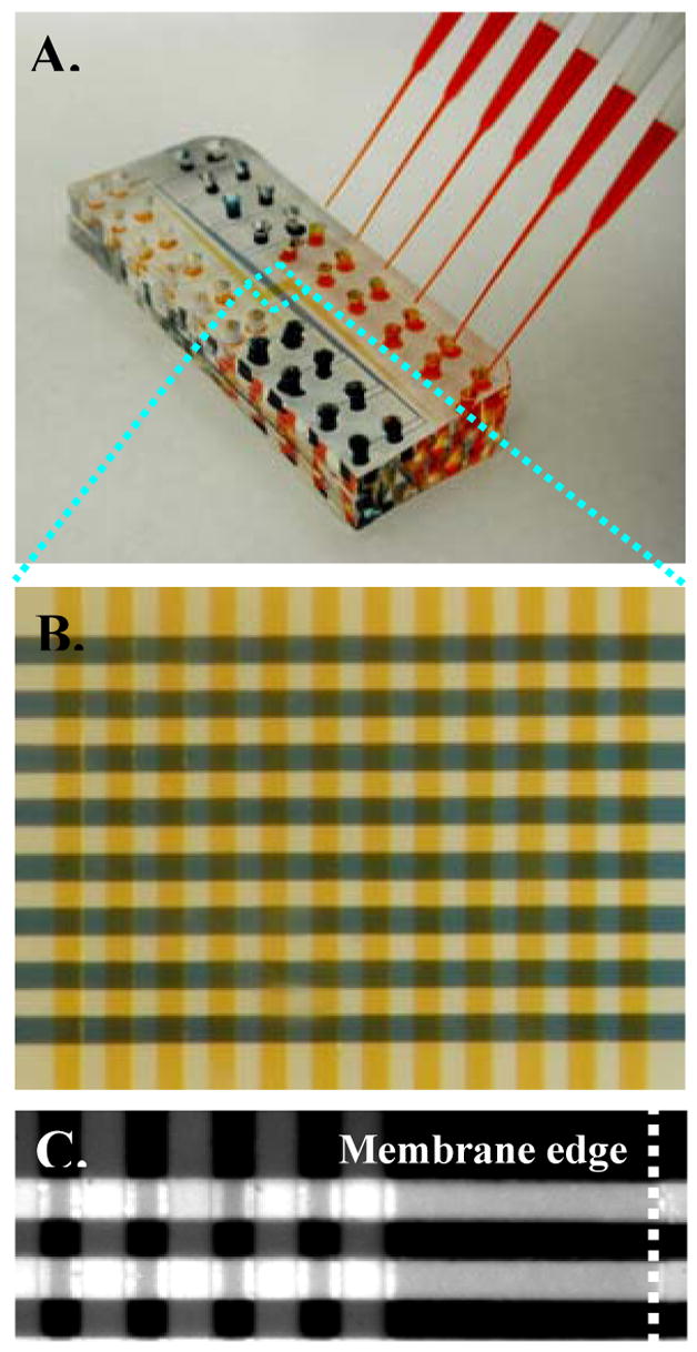
A two-layer microfluidic channel array with 96 (8 × 12) fluidic intersections. (A) A photograph of the device with a standard 6-channel pipettor loading fluid into some of the inlet reservoirs. (B) A micrograph of the area where the fluidic channel layers intersect (blue dotted lines in A). The 8 lower channels were filled with agarose gel mixed with blue solution while the 12 upper channels were filled with orange dye. A porous polyester membrane (pore size = 400 nm) was sealed between the top and bottom layers of channels. (C) Fluorescent image shows one corner of the center area of the array. The Dotted line indicates the edge of the polyester membrane. The channel was filled with a 0.01 % fluorescein solution. No leakage was observed along the edge of the membrane and no cross-talk between the microchannels. Both brightness and contrast of the original images were increased in order to enhance ability to detect any leakage along the edge of the membrane (we did not detect any). (Channel width = 100 μm. Channel height = 40 μm)
Experimental Section
Materials and reagents
Poly(dimethylsiloxane)(PDMS) (Sylgard 184) was purchase from Dow Corning (Midland, MI). SU-8 50 was purchased from MicroChem (Newton, MA). Polyester membranes were purchased from Corning Inc (Corning, NY). Polycarbonate membranes were purchased from General Electric (Fairfield, CT). Cell culture reagents were purchased from Invitrogen (Carlsbad, CA) unless otherwise mentioned. C2C12 myoblasts were provided courtesy of Dr. Shian-huey Chiang at University of Michigan, Ann Arbor. Syto 9 and Syto 64 for cell staining were also purchased from Invitrogen.
Bonding membranes into microfluidic channels
Microfluidic channels were fabricated using soft lithography23. Briefly, PDMS prepolymer was mixed with curing agent at a weight ratio of 10 (prepolymer): 1 (curing agent). The mixture was then cast onto a 4-inch silicon wafer having 40 μm-thick positive relief patterns of SU-8 50 of microchannels and cured at 60 °C overnight. The cured PDMS layer was peeled from the silicon wafer. 3 mm-diameter holes were punched through the cured PDMS substrates and used as reservoirs. To create PDMS mortar layers, PDMS and toluene were mixed at pre-determined mass ratios using a vortex mixer and the resulting mixture was allowed to sit for ~5 minutes before use to remove bubbles. The toluene diluted PDMS prepolymer was spin-coated on a clean glass cover slide for 1 minute (3 s at 500 rpm, ramped at 500 rpm/s to 1500 rpm for 60 s) to generate a thin mortar layer. The PDMS substrates with recessed microchannels were placed onto the glass slides spin-coated with adhesive PDMS mortar and allowed to stay in contact for 30 seconds. The membranes with desired sizes (5 mm × 5 mm for the 1 by 1 criss-crossing microfluidic systems shown in Fig. 2; 5 mm × 3 mm for the 8 by 12 systems shown in Fig. 1 and 4) were stamped on the edges, placed onto one of the pieces of PDMS with channel features, and gently pressed down into the mortar using tweezers. This PDMS piece with the membrane attached was then aligned and bonded together with another PDMS piece with channel features (Figure 2). The combined pieces were cured at 120 °C for at least 1 hour until the PDMS mortar was completely hardened.
Figure 2.
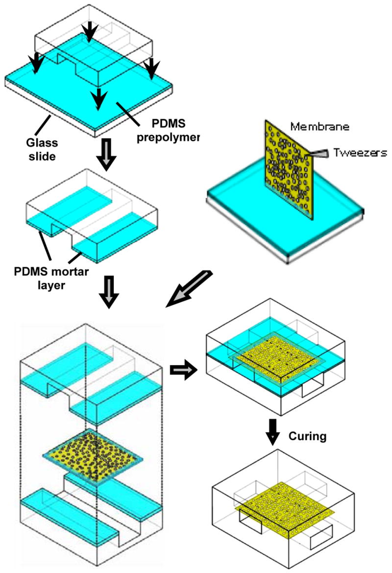
Schematic figure of the procedure for bonding membranes between two PDMS channel layers. PDMS channels are sealed using a layer of PDMS mortar generated by briefly (30 seconds) contacting the channel structure with a glass slide spin coated with a toluene-diluted PDMS prepolymer. The edge of the membrane is also stamped with the thin PDMS prepolymer before bonding the two PDMS channel layers. The combined layers are cured in a 120 °C oven for 1 hour.
Figure 4.

C2C12 cells cultured in a 8 by 12 microfluidic channel array. (A) C2C12 cells (gray circles) were seeded at a density of ~ 8.7× 10⁷ cells/mL in 8 channels comprising the top layer (pink arrows) and allowed to attach and spread on a semi porous polyester membrane (pore size = 3 μm) for three hours followed by delivery of Syto 9 (green) or Syto 64 (red) in every other channel. (B) Fluorescent image of the C2C12 cells 15 minutes after the treatment. There is a blank channel with no dye between each dye delivering channel that is just dark in the image.
Mortar layer thickness measurement
A razor blade was used to cut through the combined structure consisting of cured PDMS mortar and the original PDMS slab. The layers of the transferred mortar and the plain PDMS slab are visualized and distinguished by a clear border using an inverted phase contrast microscope with a 40X objective (Nikon, TE-300). This cross-sectional phase images of the combined structure were recorded by a CCD camera (Hamamatsu Orca-ER). The conversion ratio of the images was calibrated using a reference of a known thickness. The thickness of the solidified mortar layer was measured at five different positions from each PDMS slab.
Experimental setup for microfluidic C2C12 Cell culture
C2C12s were maintained in Dulbecco’s modified Eagle’s medium (DMEM) supplemented with 15 % fetal bovine serum (FBS), 1 % penicillin, 1 % streptomycin and 1% glutamine in humidified 5 % CO2 incubator at 37 °C. All microchannels were filled with culture medium overnight before C2C12 cell seeding. The cell suspension (~8.7× 10⁷ cells/mL) was injected into the microchannels through the reservoirs. The whole device was placed in a humidified incubator for three hours to allow cells to completely spread on the membrane to minimize convective flow through the pores. All images were taken by a CCD camera (Hamamatsu Orca-ER) mounted on an inverted microscope (Nikon, TE-300).
RESULTS AND DISCUSSION
Optimization of PDMS mortar thickness used
Unless care is taken, an unfilled gap forms along the edge of a membrane when it is sandwiched between two PDMS pieces. To avoid this problem, it is important to control the thickness and localization of the PDMS mortar that is applied. Specifically, the combined PDMS mortar layer thickness on the upper and lower PDMS pieces should be sufficient to penetrate into the pores of the porous membrane structure to form a stable bond yet not so thick to result in overflow of mortar into channel structures. It is also important to have the PDMS mortar approximately equal to the membrane thickness at the membrane edges to fill gaps there. The thickness of the stamped PDMS mortar layer can be, in turn, adjusted by changing the viscosity of uncured liquid PDMS by mixing in different portions of toluene to be spin-coated onto the cover glass. Figure 3 shows the result of different thicknesses of the PDMS mortar layer that were transferred onto plain PDMS layers (L × W × H = 50 mm × 10 mm × 2mm) after stamping with different ratios of toluene to PDMS prepolymer. For a given spin coating protocol, the thickness of the PDMS mortar transferred onto the PDMS slabs becomes thinner as the ratio of toluene to PDMS prepolymer increases (Figure 3).
Figure 3.
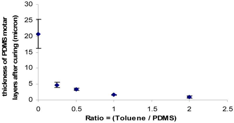
Plot of the thicknesses of PDMS mortar layers transferred to PDMS slabs by stamping the slabs onto cover glasses spin-coated with uncured PDMS diluted to different ratios of toluene to liquid PDMS.
For larger microchannels (width above 100 μm) with a simple design such as a 1 by 1 criss crossing structure, 10 μm-thick membranes can be incorporated and sealed using PDMS mortar prepared by a 1:1 ratio of toluene to PDMS. When channel widths become narrow, for example, 50 μm or arrays with closely spaced channels, PDMS mortar with a higher ratio of toluene to PDMS (2:1) is required. With this thinner PDMS mortar, it is particularly crucial to apply PDMS prepolymer to the edges of membranes to prevent leakage.
We have applied this bonding strategy to construct an 8 by 12 criss-crossing microfluidic channel array with closely spaced channels (channel width = 100 μm; channel height = 40 μm; 100 μm space between channels) as shown in Figure 1. This array was fabricated by applying ~1 μm PDMS mortar layers (generated from the ratio of toluene/PDMS = 2) to PDMS micropatterned layers that sandwiched a 10 μm-thick semi-porous polyester membrane with 3 μm pores. A fluorescein solution was introduced through channels in the 12 channel layer to visualize any leakages along the edges of the membrane or through the pores of the membrane. No fluorescence was found along the edge of the membrane or in between channels indicating a complete seal with no leakage as shown in Figure 1C.
The method is not limited to integration of polyester membranes. 10 μm-thick polycarbonate membranes with a pore size of 20 μm, which are useful for whole blood filtration or as molecular gates5,20, were also successfully incorporated and sealed. Two straight channels (width = 300 μm) were aligned parallel to each other with a polycarbonate membrane sealed in between. The PDMS mortar (~2.5 μm) in this case was prepared using a 1:1 ratio of toluene to PDMS prepolymer ratio. The combined layers were left at ambient conditions for 30 minutes before curing at 60 °C to eliminate air bubble trapped along the edge of the membrane.
Bonding strength of the membranes sealed by PDMS mortar
A two-layer, 1 × 1 channel structure (width = 300 μm, height = 50 μm) of the type shown in Figure 2 was used to test the strength of structures sealed using PDMS mortar. Both channels were filled with fluorescein solution and tubing connected to the two outlet reservoirs were closed using binder clips. The two inlets were pressurized via tubing connected to a Y-shaped connector and a nitrogen gas source.
The burst resistance of different thickness PDMS mortar used for one-sided and two-sided mortar application was tested. The bonding strength was stronger, in general, with thicker PDMS mortar and with two-sided, rather than one-sided, mortar application. For example, channels fabricated using 2.5 μm PDMS mortar (toluene:PDMS prepolymer = 1:1) application showed a burst resistance of ~ 100 kPa for one-sided mortar application, whereas the burst resistance was above our measurement limit of ~120 kPa for two-sided application. With 1 μm PDMS mortar application (toluene: PDMS prepolymer = 2:1) one-sided application failed whereas the two-sided mortar application still showed strong bonding (above measurement limit). The burst resistance of the 8 by 12 criss-crossing microfluidic array systems sandwiching a 3 μm pore membrane was also measured and found to have a strong seal that is above our measurement limit of ~120 kPa. The result indicates the robustness of the bonding even in microfluidic channel arrays with closely spaced channels.
Cell Culture in 8 by 12 criss-crossing microfluidic array systems
The criss-crossing microfluidic array system, of the type shown in figure 1, is promising for performing efficient screens of how different subpopulations of cells respond to different reagents. Here optically transparent semi-porous polyester membranes with 3 μm pores were specifically cut out from clear polyester Transwell® plates and integrated into the device, rather than using off-the-shelf polyester membranes which are more opaque. This is helpful for direct observation and imaging of cells in the channels. Two fluorescent nucleic acid dyes, Syto 9 and Syto 64 (100 μM), were introduced alternately in every other channel with one “blank” channel in between (Fig. 4A). Figure 4B shows differential staining of cells after applying the dyes for 15 minutes. C2C12 cells stained with Syto 9 became green fluorescent (24 intersections), whereas cells stained with Syto 64 became red fluorescent (24 intersections), and cells in lanes not exposed to the dyes remained dark (48 intersections). There was relatively little cross-talk of reagents between neighboring intersections within the first 15 minutes of this experiment. Diffusion of the stains toward adjacent channel intersections did start to become apparent for green and red fluorescence gradually beyond 20 minutes. Such diffusive effects will have to be accounted for when performing experiments in these arrays. On the other hand, such diffusive effects can also be taken advantage of, for example, to expose cells to concentration gradients of multiple chemicals under non-flowing conditions21. Use of membranes with smaller pores can also be used to suppress diffusion.
The concept of using criss-crossing microchannel architectures is capable of quadratic increases in the combinations of cells and reagents tested with only linear increases in the number of channels1. A practical challenge for taking advantage of such attractive concepts is the efficient and reliable integration and leakage-free bonding of semi-porous membranes into microchannel systems1,16. The PDMS mortaring method described in this paper provides a solution to this challenge. This bonding method has the advantage of being experimentally straightforward, inexpensive, and applicable to a range of different channel sizes (50, 100 and 300 μm) and membrane types (polyester and polycarbonate).
In this study, the ratios of toluene to PDMS used were 1 and 2. Thicker mortar layers (Toluene: PDMS = 1:1) were applied to fabricate simple devices with wider channels (above 100 μm) and it was shown that one-sided mortar application provided sufficient bonding strength in this case. Thinner mortar layers (Toluene: PDMS = 2:1) were better suited for fabrication of microfluidic arrays with closely space microchannels such as the 8 by 12 criss-crossing channels. Coating the edges of membranes with mortar (~1 μm thickness) is critical for eliminating crevices. Tweezers with fine tips were used to hold one corner of the membrane tightly while a PDMS mortar coated cover glass was brought into contact.
As the thickness of the membranes becomes thicker and the channel dimension becomes smaller, there will eventually be a size combination where this method will cause channel clogging. For many applications, particularly those that involve living mammalian cells, the method described here should be sufficient because the cells themselves are on the order of 10 microns or larger and seldom require channels smaller than ~100 microns in width.
Conclusion
In summary, we have demonstrated a simple, useful and robust bonding method to integrate 10 μm-thick membranes into 2-layer PDMS microfluidic systems using uncured PDMS as mortar to bond the different components together. This sealing method conveniently eliminates the gap generated at membrane edges without channel clogging. We have demonstrated this method with polyester and polycarbonate membranes having three different pore sizes (0.4, 3, 20 μm) and believe it will be applicable for use with a wide range of membrane types. The specific 8 × 12 criss-crossing microfluidic array system described here has advantages of requiring small amounts of reagents and cells, of straightforward fabrication, of compatibility with commercial multi-channel pipetters, and of efficient imaging. Information for all 96 combinations fit within the footprint of a single well in a 96 well plate. The fluorescent reagent experiments, although simple, show the compatibility of this system to mammalian cell culture, the ability to subject cells to distinct reagents in different intersections for periods of ~15 minutes, and the ability to expose cells to chemical gradients in longer experiments.21 These devices and methods are envisioned to be useful for a variety of parallel biological and chemical analyses such as immunoassays, drug screening, or cell-based biosensing.
Acknowledgments
We thank Yi-chung Tung, Ying Zheng and Xinran (Maria) Xiang for assisting channel fabrication and Andreja Jovic for proofreading. This material is based upon work supported in part by the U.S. Army Research Laboratory and the U.S. Army Research Office under contract/grant number DAAD 19-03-1-0168 and by the NIH (HL084370-01).
References
- 1.Ismagilov RF, Ng JMK, Kenis PA, Whitesides GM. Anal Chem. 2001;73:5207–5213. doi: 10.1021/ac010502a. [DOI] [PubMed] [Google Scholar]
- 2.Tani H, Maehana K, Kamidate T. Anal Chem. 2004;76:6693–6697. doi: 10.1021/ac049401d. [DOI] [PubMed] [Google Scholar]
- 3.Bernard A, Michel B, Delamarche E. Anal Chem. 2001;73:8–12. doi: 10.1021/ac0008845. [DOI] [PubMed] [Google Scholar]
- 4.Anderson DG, Levenberg S, Langer R. Nature Biotechnol. 2004;22:863–866. doi: 10.1038/nbt981. [DOI] [PubMed] [Google Scholar]
- 5.Kuo T-C, Cannon DM, Jr, Shannon MA, Bohn PW, Sweedler JV. Sensors and Actuators A. 2003;102:223–233. [Google Scholar]
- 6.Khademhosseini A, Langer R, Borenstein J, Vacanti JP. Proc Natl Acad Sci USA. 2006;103:2480–2487. doi: 10.1073/pnas.0507681102. [DOI] [PMC free article] [PubMed] [Google Scholar]
- 7.Junker D, Schmid H, Delamarche E. Nat Mater. 2005;4:622–628. doi: 10.1038/nmat1435. [DOI] [PubMed] [Google Scholar]
- 8.Shelby JC, Shannon MA, Xu K, Economy J. J Micromech Micoeng. 2001;11:672–685. [Google Scholar]
- 9.Flachsbart ER, Wong K, Iannacone JM, Abante EN, Vlach RL, Rauchfuss RA, Bohn PW, Sweedler JV, Shannon MA. Lab Chip. 2006;6:667–674. doi: 10.1039/b514300d. [DOI] [PubMed] [Google Scholar]
- 10.Sia SK, Whitesides GM. Electrophoresis. 2003;24:3563–3576. doi: 10.1002/elps.200305584. [DOI] [PubMed] [Google Scholar]
- 11.Takayama S, McDonald JC, Ostuni E, Liang MN, Kenis PJA, Ismagilov RF, Whitesides GM. Proc Natl Acad Sci USA. 1999;96:5545–5548. doi: 10.1073/pnas.96.10.5545. [DOI] [PMC free article] [PubMed] [Google Scholar]
- 12.Unger MA, Chou HP, Thorsen T, Scherer A, Quake SR. Science. 2000;288:113–116. doi: 10.1126/science.288.5463.113. [DOI] [PubMed] [Google Scholar]
- 13.Song JW, Gu W, Futai N, Warner KA, Nor JE, Takayama S. Anal Chem. 2005;77:3993–3999. doi: 10.1021/ac050131o. [DOI] [PubMed] [Google Scholar]
- 14.Jeon NL, Baskaran H, Dertinger SKW, Whitesides GM, Van de Water L, Toner M. Nat Biotechnol. 2002;20:826–830. doi: 10.1038/nbt712. [DOI] [PubMed] [Google Scholar]
- 15.Zhu XY, Mills KL, Peters PR, Bahng JH, Liu EH, Shim J, Naruse K, Csete ME, Thouless MD, Takayama S. Nat Mater. 2005;4:403–406. doi: 10.1038/nmat1365. [DOI] [PubMed] [Google Scholar]
- 16.Jong JD, Lammertink RGH. Wessling, Lab Chip. 2006;6:1125–1139. doi: 10.1039/b603275c. [DOI] [PubMed] [Google Scholar]
- 17.Cannon DM, Jr, Kuo T-CMA, Bohn PW, Sweedler JV. Anal Chem. 2003;75:2224–2230. doi: 10.1021/ac020629f. [DOI] [PubMed] [Google Scholar]
- 18.Tulock JJ, Shannon MA, Bohn PW, Sweedler JV. Anal Chem. 2004;76:6419–6425. doi: 10.1021/ac049601p. [DOI] [PubMed] [Google Scholar]
- 19.Wu H, Huang B, Zare RN. Lab Chip. 2005;5:1393–1398. doi: 10.1039/b510494g. [DOI] [PubMed] [Google Scholar]
- 20.Thorslund S, Klett O, Nikolajeff F, Markides K, Jonas Bergquist J. Biomed Microdevices. 2006;8:73–79. doi: 10.1007/s10544-006-6385-7. [DOI] [PubMed] [Google Scholar]
- 21.Abhyankar VV, Lokuta MA, Huttenlocher A, Beebe DJ. Lab Chip. 2006;6:389–393. doi: 10.1039/b514133h. [DOI] [PubMed] [Google Scholar]
- 22.Ostrovidov S, Jiang J, Sakai Y, Fujii T. Biomed Microdevices. 2004;6:279–287. doi: 10.1023/B:BMMD.0000048560.96140.ca. [DOI] [PubMed] [Google Scholar]
- 23.Duffy DC, McDonald JC, Schueller OJA, Whitesides GM. Anal Chem. 1998;70:4974–4984. doi: 10.1021/ac980656z. [DOI] [PubMed] [Google Scholar]