Abstract
We describe a field-lock/field-sweep system for the use in superconducting magnets. The system is based on a commercially available field mapping unit and a custom designed broad-band 1H-NMR probe. The NMR signal of a small water sample is used in a feedback loop to set and control the magnetic field to high accuracy. The current instrumental configuration allows field sweeps of ± 0.4 T and a resolution of up to 10-5 T (0.1 G) and the performance of the system is demonstrated in a high-field electron paramagnetic resonance (EPR) application. The system should also be of utility in other experiments requiring precise and reproducible sweeps of the magnetic field such as DNP, ENDOR or PELDOR.
Keywords: Field-Lock, High-Field EPR, Superconducting Magnets
Introduction
The last two decades has witnessed substantial progress in microwave (mw) technology that has in turn facilitated the development of several high-field/high-frequency electron paramagnetic resonance (HF-EPR) spectrometers in laboratories around the world. As a consequence, commercial spectrometers are available up to 95 GHz and custom designed high-field EPR spectrometers are currently operating from 95 up to 360 GHz [1-6] and the applications of high-field EPR are manifold and expanding rapidly [7,8].
The breadth of high field EPR spectra can easily exceed several hundred MHz and it is therefore customary to perform high field EPR experiments by monitoring the signal at a fixed mw frequency, while the magnetic field is swept in order to record the complete spectrum. Both echo detected and continuous wave (CW) schemes are used for this purpose. The magnetic field sweep is performed by changing the current in a sweep coil or in the main coil and the field position is typically calibrated using Mn2+ [9] or Cr5+ [10] standards. Unfortunately, signals from these field calibration species sometimes interfere with the analysis of the spectra. Furthermore, In order to compensate for hysteresis effects, the sweep of the magnetic field has to start at much lower (or higher) field position than the first resonance appears. Many other experiments, such as ENDOR [11,12], PELDOR [11] or DNP [13] require fixed, reproducible and stable magnetic field values, which are difficult to achieve at high magnetic fields using only control of the magnet or sweep coil current without any feedback loops.
Primarily for these reasons we developed a field control based on an analog NMR field lock system that we described in a previous publication [14] and has some similarities to a field-frequency lock system based on a 19F signal used in previous Bruker systems. However, those systems are not readily available to the EPR community since our NMR spectrometer was a custom design, constructed in-house.
Here we describe and demonstrate the use of a state-of-the-art field control system that is based on a commercially available field mapping unit (FMU) that controls the magnetic field to high accuracy. In particular, the proton signal of a small water sample is used in a feedback loop to control and set the magnetic field. This field-lock system replaces the analog system described previously [14].
Instrumentation
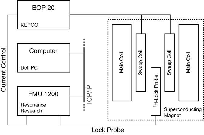
The field-lock system we have assembled consists of a superconducting magnet, a bipolar power supply, a field-mapping unit and a custom designed broadband NMR probe. A PC running LabView (National Instruments, Austin, TX, USA) controls all of these components. A schematic overview of the field-lock system is shown in Figure 1. The detailed specifications of the EPR spectrometer and related components is described elsewhere [12].
Figure 1.

Schematic representation of the sweep control system. The system consists of a superconducting magnet, a bipolar power supply, a field-mapping unit and a home-built broadband NMR probe. All components are controlled by a PC, running LabView. Communication between the computer and the FMU is accomplished via TCP/IP. The sweep-coil current is controlled by an analog voltage supplied by the DAC-card of the FMU.
The superconducting magnet (Magnex Scientific Limited, Oxford, UK) consists of two superconducting coils-a main coil that provides a static magnetic field of 5 T and a small sweep coil, on the outside of the main coil, to sweep the magnetic field by ± 0.4 T (g = 1.84 -2.16), with a current of ± 14 A. Due to the lower inductance and design of the sweep coil, there is reduced hysteresis in the sweep, rapid stabilization of the magnetic field, and concurrently the He boil-off rate is reduced in comparison with sweeps involving the main coil. The current to drive the sweep coil is provided by a bipolar power supply (KEPCO, Model BOP 20-20M, Flushing, NY, USA), and an analog input voltage to the supply provides remote control of the current. In order to perform low temperature experiments the system is equipped with a SpectrostatCF cryostat (Oxford Instruments, Abingdon, UK).
The field-mapping unit (FMU 1200, Resonance Research, Billerica, MA, USA) is a commercially available device originally intended for use in the shimming of superconducting magnets. The unit records a pseudo-continuous wave NMR spectrum by measuring the intensity of a free induction decay following an rf-pulse at a given acquisition delay, while sweeping the rf-frequency of the transmitter. In a typical field scan, 1000 points are recorded, with a dwell time of 1 ms and the entire sweep is performed in 1 s. However, if the expected frequency is known approximately, it is possible to reduce the number of points in the scan and shorten the acquisition time. Furthermore, a 16 bit digital analog converter (DAC) whose output is under user control was added to the FMU 1200. The output of this card is used in our application to remotely control the current of the BOP power supply.
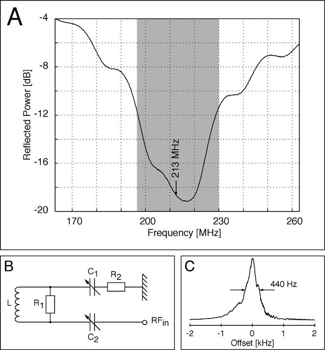
In order to measure the 1H-NMR signal over a range of ± 0.4 T a special broad-band 1H-NMR probe is required. The design and characteristics of the probe are shown in Figure 2 (A and B). The source of the proton signal is a small water sample in a 2.2 mm (o.d.) quartz capillary of 12 mm length located outside, below the cryostat but still in the homogenous region of the magnetic field. For the sample tap water was used since the paramagnetic impurities shorten the nuclear spin-lattice relaxation times and increase the NMR line width. Reasonable sweep rates require that the line width is not too narrow and the large inductance and the small resistance of the sweep coil act as a low-pass filter to filter out any high-frequency power fluctuations.
Figure 2.

Design of the field lock probe. A) Reflected power of the tuned probe over a range of 110 MHz. B) Circuit design of the lock probe consisting of a rf-coil L (7 turns, copper, AWG 16), resistor R1 (1.8 kΩ) in parallel with the rf-coil, resistor R2 (50 Ω) and two variable capacitors C1 and C2 (each 2-8 pF). C). Proton signal of the water sample.
The capillary is sealed with epoxy resin, to prevent evaporation and the sample is held by the rf-coil and oriented transversely in the magnetic field. The proton spectrum at B0 = 5 T is shown in Figure 2 (C) and has a constant line width of 440 Hz over the entire sweep range of the sweep coil. In contrast to the system described previously [14], variable tuning is not required in order to cover the complete sweep range (corresponding to ∼40 MHz) (gray area in Figure 2 A). The low-Q of the resonance circuit was achieved by using a resistor (R1) in parallel with the rf-coil (see Figure 2 B), the second resistor (R2) is used to match the impedance.
The initial locking procedure as well as the sweep of the magnetic field is under control of a LabView program. Instead of a detailed description of the LabView programs, which are used to control the field lock system, a more general description of the routines is given in the appendix, since nowadays the hard- and software which are used to control home built spectrometers quickly become. out-of-date.
Results and Discussion
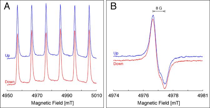
To demonstrate the performance of our system we chose three different paramagnetic samples that exhibit representative spectral widths in high-field EPR experiments. Figure 3A shows an echo-detected field-sweep EPR spectrum of 1 mM manganese acetate diluted in glycerol/water and recorded at a temperature of 10 K. This first example demonstrates the case of a broad EPR spectrum, which is typical for (high-spin) transition metals having a large g-anisotropy or large hyperfine interactions. The spectrum shows six sharp lines, a pattern which is typical for octahedral coordinated Mn2+ ions [15] and is often used to calibrate the magnetic field in high-field EPR experiments [9]. No difference in line shapes or peak positions are observed in the spectrum when the magnetic field is swept either up or down.
Figure 3.

140 GHz Echo-detected field-sweep EPR spectra. A) 1 mM Mn-Acetate in Glycerol/Water (60/40, w/w), T = 10 K, tp = 40 ns, τ = 400 ns, the mw-power was adjusted by monitoring the shape of the two-pulse echo. Magnetic field scan in both directions (up/down) over 600 G, field resolution: 2 G. B) 2% 2H-BDPA/PS, T = RT, tp = 48 ns, τ = 400 ns. Magnetic field scan in both directions (up/down) over 60 G, field resolution: 0.5 G. Integration two-pulse echo was performed using a BoxCar integrator.
The second example represents the case of an intermediate to small EPR line width, which is typically found for organic radicals with small g-anisotropies and hyperfine interactions hidden by the inhomogeneous EPR line width. Figure 3B shows the echo-detected field-sweep EPR spectrum of a sample of 2 % perdeuterated BDPA in polystyrene recorded at room temperature. The spectrum has a peak-to-peak width of 8 G and shows some structure due to the small anisotropy of the g-tensor. The spectrum was recorded with a field resolution of 0.5 G per point and the spectrum recorded with the scan direction upward is identical to that recorded with the opposite direction of the magnetic field sweep.
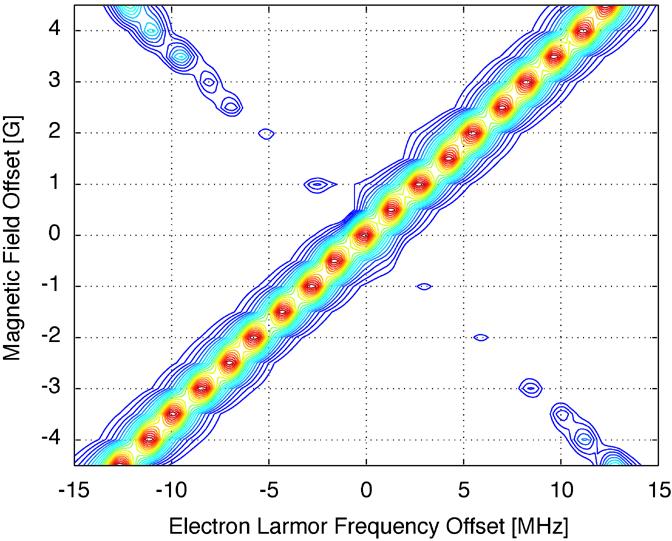
For the third example a perylene single crystal sample was chosen in order to demonstrate the resolution at high field, which can be achieved using the field mapping unit. A series of free induction decays (FIDs) were recorded for different offsets of the magnetic field with respect to the field provided by the main magnet coil. Figure 4 shows a two-dimensional representation of the complex Fourier transform time domain traces with respect to the magnetic field offset. It can be seen that the resonance position of the FID shifts linearly with the magnetic field offset. A linear regression analysis of the resonance frequency of the perylene sample versus the magnetic field offset gives a slope of 1 (R2 = 0.9998) indicating that the steps of the magnetic field are highly accurate. By increasing the number of refinement steps the field resolution can be increased to 0.1 G corresponding to a field resolution of 2 ppm. While this increases the time required to set a specific field position, it nevertheless allows a highly accurate determination of g-values. For standard applications a field resolution of 0.5 G (10 ppm) is usually sufficient. A good indicator for the field stability is the frequency noise of a perylene FID measured in two consecutive shots. From that a field jitter of about 50 kHz (0.4 ppm) was determined, a rather small value which is mainly due to the large inductance of the superconducting sweep coil.
Figure 4.

Series of Fourier transformed FIDs of a perylene single crystal recorded at different magnetic field positions. The magnetic field offset (ordinate) was stepped in steps of 0.5 G over a range of 9 G. For better representation, the static field was subtracted. Other parameters: T = RT, tp = 80 ns. The complex time trace was acquired using a LeCroy Waverunner 6200 digital oscilloscope. 2500 points were taken in the time domain, with a dwell-time of 2 ns. DC-correction, apodization by a Hamming window and zero filling to 4096 points was performed prior to Fourier transformation. Absolute value spectra are shown in the figure. The low-intensity features are due to the large carrier offset of the mw-frequency.
Conclusion
We have designed and constructed a system for controlling and sweeping the magnetic field in high-field EPR experiments that is based on a commercially available field-mapping unit and a home built 1H-NMR probe. The system can be used to control the entire sweep range of ± 0.4 T with a stability of up to 2 ppm. The major advantages of the present system are that no additional g-standards are necessary to calibrate the magnetic field and that the magnetic field can be set with a high degree of reproducibility, which is required for experiments performed at a fixed field position such as PELDOR, ENDOR or DNP.
Acknowledgements
This research was supported by the National Institute of Health (Grant EB-002804 and EB-002026). T.M. wishes to thank the Deutsche Forschungs Gesellschaft for a Postdoctoral Fellowship. The authors are also grateful to Deborah Martino, Kan-Nian Hu, and Melanie Hertel (Frankfurt am Main, Germany) and the two anonymous reviewers for their helpful comments and stimulating discussions.
Appendix
Initial Calibration
After the initial setup of the system, the output of the DAC-card is calibrated with respect to the magnetic field. Accordingly we measured the 1H frequency for several different values of the DAC-card output and the proportionality constant between the DAC-card output and the magnetic field was obtained by linear regression. This procedure has to be performed only once, and the constant is used later in order to calculate the corresponding change of the magnetic field with respect to the DAC-card output.
Field-Frequency Lock
After switching on the spectrometer, the actual field position and therefore the lock-frequency is determined by several (usually 5) scans with decreasing spectral widths. This procedure is repeated, each time the spectrometer is activated.
Magnetic Field Sweep
In order to perform a sweep of the magnetic field, the sweep coil current is first stepped in coarse steps (corresponding to 5 G) to a region close to the desired field value. Afterwards the magnetic field is changed by the smallest value of the DAC-card approaching the desired field position. This is done using a PI-routine (P-Proportional, I-Integration), which compensates the difference between the actual and the desired field value. This routine is looped and is stopped if the difference between actual and desired field position is within a predefined error-boundary. Usually three cycles of refinement are sufficient to set the magnetic field to high accuracy; however, the loop will be terminated if the loop-counter exceeds a predefined number.
During large sweeps of the magnetic field, it is necessary to keep track of the lock signal. Therefore the actual field is determined in an additional sweep every 50 G. This intermediate frequency is used to correct the field position calculated from the output of the DAC-card.
Footnotes
Publisher's Disclaimer: This is a PDF file of an unedited manuscript that has been accepted for publication. As a service to our customers we are providing this early version of the manuscript. The manuscript will undergo copyediting, typesetting, and review of the resulting proof before it is published in its final citable form. Please note that during the production process errors may be discovered which could affect the content, and all legal disclaimers that apply to the journal pertain.
References
- 1.Prisner T, Rohrer M, Möbius K. Pulsed 95 GHz High-Field EPR Heterodyne Spectrometer with High Spectral and Time Resolution. Appl. Magn. Reson. 1994;7:167–183. [Google Scholar]
- 2.Earle KA, Dzikobski B, Hofbauer W, K. MJ, Freed JH. High-Frequency ESR at ACERT. Magn. Reson. Chem. 2005;43:256–266. doi: 10.1002/mrc.1684. [DOI] [PubMed] [Google Scholar]
- 3.Becerra LR, Gerfen GJ, Bellew BF, Bryant JA, Hall DA, Inati SJ, Wever RT, Un S, Prisner TF, McDermott AE, Fishbein KW, Kreischer KE, Temkin RJ, Singel DJ, Griffin RG. A Spectrometer for Dynamic Nuclear Polarization and Electron Paramagnetic Resonance at High Frequencies. J. Magn. Reson. Ser. A. 1995;117:28–40. [Google Scholar]
- 4.Rohrer M, Brügmann O, Kinzer B, Prisner T. High-Field/High-Frequency EPR Spectrometer Operating in Pulsed and Continous-Wave Mode at 180 GHz. Appl. Magn. Reson. 2001;21:257–274. [Google Scholar]
- 5.Blok H, Disselhorst JAJM, Orlinski SB, Schmidt J. A Continous-Wave and Pulsed Electron Spin Resonance Spectrometer Operating at 275 GHz. J. Magn. Reson. 2004;166:92–99. doi: 10.1016/j.jmr.2003.10.011. [DOI] [PubMed] [Google Scholar]
- 6.Fuchs MR, Prisner T, Möbius K. A High-Field/High-Frequency Heterodyne Induction-Mode Electron Paramagnetic Resonance Spectrometer Operating at 360 GHz. Rev. Sci. Inst. 1999;70:3681–3683. [Google Scholar]
- 7.Bennati M, Prisner T. New Developments in High Field Electron Paramagnetic Resonance with Application in Structural Biology. Rep. Prog. Phys. 2005;68:411–448. [Google Scholar]
- 8.Grindberg O, Berliner L. Very High Frequency ESR/EPR. Plenum; New York: 2005. [Google Scholar]
- 9.Burghaus O, Rohrer M, Götzinger T, Plato M, Möbius K. A Novel High-Field/High-Frequency EPR and ENDOR Spectrometer operating at 3 mm Wavelength. Meas. Sci. Technol. 1992;3:765–774. [Google Scholar]
- 10.Cage B, Weekley A, Brunel L-C, Dalal NS. K3CrO8 in K3NbO8 as a Proposed Standard for g-Factor, Spin Concentration, and Field Calibration in High-Field EPR Spectroscopy. Anal. Chem. 1999;71:1951–1957. [Google Scholar]
- 11.Hertel MM, Denysenkov VP, Bennati M, Prisner TF. Pulsed 180-GHz EPR/ENDOR/PELDOR spectroscopy. Magn. Reson. Chem. 2005;43:248–255. doi: 10.1002/mrc.1681. [DOI] [PubMed] [Google Scholar]
- 12.Bennati M, Farrar CT, Bryant JA, Inati SJ, Weis V, Gerfen GJ, Riggs-Gelasco P, Stubbe J, Griffin RG. Pulsed Electron-Nuclear Double Resonance (ENDOR) at 140 GHz. J. Magn. Reson. 1999;138:232–243. doi: 10.1006/jmre.1999.1727. [DOI] [PubMed] [Google Scholar]
- 13.Weis V, Griffin RG. Electron-Nuclear Cross Polarization. Solid State Nuclear Magnetic Resonance. 2006;29:105–117. doi: 10.1016/j.ssnmr.2005.08.005. [DOI] [PubMed] [Google Scholar]
- 14.Un S, Bryant J, Griffin RG. Precision Field-Sweep System for Superconducting Solenoids and Its Application to High-Frequency EPR Spectroscopy. J. Magn. Reson. Ser. A. 1993;101:92–94. [Google Scholar]
- 15.Low W. Paramagnetic Resonance Spectrum of Manganese in Cubic MgO and CaF2. Phys. Rev. 1957;3:793–800. [Google Scholar]


