

The galvanic replacement reaction provides a simple and effective method for preparing hollow nanostructures of noble metals including Au, Pd, and Pt when Ag nanostructures are used as sacrificial templates.[1] These hollow nanostructures are enclosed by continuous or porous walls with a tunable/controllable thickness. For Au-based hollow nanostructures such as nanoboxes and nanocages, reduction of the wall thickness would lead to a red-shift for the localized surface plasmon resonance (LSPR) peak.[2] Significantly, when the LSPR peak is tuned into the near-infrared region from 800 to 900 nm (the so-called transparent window of soft tissues), these nanostructures hold great promise for a variety of biomedical applications that may include drug delivery,[3] contrast-enhanced optical imaging,[4] and photothermal therapy.[5]
When an aqueous suspension of Ag nanocubes (the sacrificial template) is titrated with an aqueous solution of AuCl4−, the galvanic replacement reaction between these two species occurs immediately, leading to the formation of Au-based nanoboxes and eventually nanocages. This reaction follows a template-engaged hollowing-out mechanism.[6] Briefly, AuCl4− oxidizes the sacrificial Ag template to AgCl, which is highly soluble at the elevated reaction temperature (Eq. 1).[7] Note that the standard reduction potential of the AuCl4−/Au pair (0.99 V vs. the standard hydrogen electrode, SHE) is higher than that of the AgCl/Ag pair (0.22 V). The electrons generated in the oxidation process migrate to the surface of the Ag cubes, where they reduce AuCl4− to Au atoms. Because Au and Ag solids share the same face-centered cubic structure with closely matched lattice constants (4.0786 and 4.0862Å, respectively), the Au atoms are able to epitaxially nucleate and grow on the surface of the Ag template. In the initial step of the reaction, a small pit is generated on the surface of each nanocube, allowing ionic species to continuously diffuse in and out of the oxidation site. As the reaction proceeds this pit evolves into a deep hole, with its opening at the surface eventually being closed. This process results in a seamless nanobox composed of a Au/Ag alloy. Finally, by adding more AuCl4− solution dealloying of the nanobox occurs, leading to the formation of a Au-based nanocage with porous walls.[8]
| (1) |
According to the stoichiometry between Ag and AuCl4− (Eq. 1), only one Au atom is formed for every three Ag atoms that are removed. If the AuCl4− is replaced by a precursor such as AuCl2−, the stoichiometry will be changed owing to the difference in oxidation number of gold. For the Au(I) precursor, one Au atom will be formed for every Ag atom being oxidized. This change to the amount of Ag consumed relative to the amount of Au generated during the reaction could impact the alloying/dealloying processes. It is also possible that additional flexibility regarding the morphology, wall thickness, and LSPR position of the resultant hollow nanostructures could be achieved by using precursors with different oxidation numbers for gold. Herein, we report a detailed study of the galvanic replacement reaction between Ag nanocubes and AuCl2− in close comparison with the reaction involving AuCl4−. Because the standard reduction potential of the AuCl2−/Au pair (1.11 V vs. SHE) is also higher than that of AgCl/Ag, Ag nanocubes can still be oxidized by AuCl2−.[9] In addition, AuCl2− reacts with Ag to form the same products as the reaction between AuCl4− and Ag, thus providing a meaningful comparison for the galvanic replacement reactions involving Au(I) and Au(III) precursors.
| (2) |
The Ag nanocubes used as sacrificial templates were synthesized by using a sulfide-mediated polyol process and had a mean edge length of 52±4 nm.[10] The galvanic replacement reaction was performed following a previously reported procedure;[8] however, owing to the low solubility of AuCl in water a saturated aqueous solution of NaCl was used to dissolve the AuCl through complexation to form water-soluble NaAuCl2 species. Note that the presence of excess NaCl in the reaction solution will also make the AgCl soluble by forming a AgCl2− complex. We only used freshly prepared AuCl2− solutions to avoid its disproportionation, according to Equation 3:
| (3) |
Figure 1 shows scanning electron microscopy (SEM) and transmission electron microscopy (TEM) images of the nanostructures obtained at different stages of the reactions between Ag nanocubes and an aqueous AuCl2− solution (Fig. 1A–D). For comparison, SEM and TEM images of the products obtained with the use of AuCl4− solution at the same concentration are also included (Fig. 1E–H). At each stage, the volume of AuCl4− solution added to the Ag nanocube suspension was kept at 1/3 of the volume of AuCl2−, so that ideally the same amount of Ag would be dissolved from the template. At the initial stage of the reaction with AuCl2−, the Ag nanocubes went through a pitting process in which a pinhole in one of the six {100} faces was observed (Fig. 1A). As the reaction proceeded, the pinhole disappeared and a void developed, which then enlarged within each nanocube template (Fig. 1B and C). In the later stages of the reaction, the template was transformed into a cubic void, yielding nanoboxes with a wall thickness of 10.5±1 nm (Fig. 1D). The outer and inner edge lengths of the nanoboxes were 64±4 nm and 43±4 nm, respectively. The hollow structures were free of large pores or pinholes in the walls, and the corners were slightly truncated.
Figure 1.
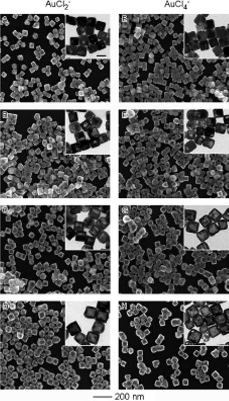
SEM and TEM (insets) images showing four different stages involved in the galvanic replacement reaction, in which Ag nanocubes were titrated with A) 1.0, B) 3.0, C) 5.0, and D) 10.0 mL of 0.1 mm AuCl2−; and E) 0.3, F) 1.0, G) 1.6, and H) 3.3 mL of 0.1 mm AuCl4−. The scale bar in the inset in (A) represents 50 nm and applies to all TEM images.
For the control experiments involving Ag nanocubes and AuCl4−, the reaction followed the same mechanism as that which has been discussed in detail in our previous publications.[8] At the early stage, a thin layer of gold formed on the outside of the nanocube and a small pit was observed on one of the six {100} faces (Fig. 1E). As more AuCl4− solution was added, the interior of the template continuously dissolved to yield a nanobox through a combination of galvanic replacement and alloying between Ag and Au (Fig. 1F and G). In the later stages, nanocages, with hollow interiors and porous walls, were obtained through dealloying of the walls of the nanoboxes (Fig. 1H). The outer edge length of the nanocages was 60±4 nm, together with a wall thickness of 8±1 nm. By a quick comparison, it is apparent that some morphological differences have resulted from using precursors with different oxidation numbers for gold.
Figure 2 schematically summarizes the replacement reaction pathways when Ag nanocubes are reacted with AuCl2− and AuCl4− (Fig. 2A and B, respectively). During the initial stage of both reactions, a thin layer of Au is formed on the surface of the nanocube template. Assuming that the deposited layer of Au can prevent the Ag underneath from being oxidized, a pinhole can serve as the active site for Ag dissolution from the interior of the template. With AuCl2−, the pinhole disappears with the addition of only a small amount of precursor, marking the second stage of the reaction. In contrast, with AuCl4−, the pinhole remains open until much more precursor is added in the third stage of the reaction. The early disappearance of the pinhole for the reaction with AuCl2− can be attributed to the 1:1 molar ratio between generated Au and consumed Ag, that is, more Au(0) is deposited per Ag atom being oxidized than is the case when AuCl4− is used. Consequently, dissolution of the Ag template for the reaction with AuCl2− requires a greater volume of precursor solution (stage 4 vs. stage 3 in Fig. 2) than when AuCl4− is used because there is no pinhole for the reaction species to diffuse in and out from for the former system. Instead, the Ag atoms must diffuse through the Au layer in order to be oxidized and dissolved from the template. Concurrent with the replacement reaction, alloying between Au and Ag occurs because the diffusion rates of Au and Ag are relatively high at 100 °C[11] and the Au/Ag alloy is more stable than pure Au or Ag.[12]
Figure 2.
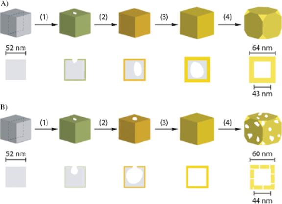
Schematic detailing the major differences in terms of morphological and structural changes during the galvanic replacement reaction involving Ag nanocubes with A) AuCl2− and B) AuCl4− in an aqueous medium. The cross-sectional view corresponds to the plane along the dashed lines.
The hollow nanostructures obtained from the reactions with AuCl2− and AuCl4− exhibit similar void sizes after the fourth stage, although for both cases the void sizes are smaller than the original Ag template. The difference between the dimensions of the void and the initial Ag template can be attributed to interdiffusion between Ag and Au, that is, Ag diffuses away from the core and towards the surface of the template as Au diffuses into the Ag layer. This interdiffusion causes a ca. 20% reduction for the void size as compared to the dimensions of the Ag nanocube. A similar size change has been reported in nanostructure systems involving the Kirkendall effect.[13] In these systems, vacancies are formed because of a difference in diffusion rate for the two components. Although interdiffusion between Au and Ag occurs in our system as well, the formation of a hollow interior can be primarily attributed to the template-engaged replacement reaction, where Ag leaves the template owing to oxidation. As proposed in the void growth process via Kirkendall-diffusion, small voids are formed near the interface, which then grow in size over time via coalescence.[13] We have not observed this behavior in the Au/Ag galvanic replacement reaction system. Rather, the void is initiated at the pinhole site and then enlarged to occupy the entire template.
In addition to the morphological changes, the galvanic replacement reaction between Ag nanocubes and AuCl2− went through a series of color changes from yellow to orange, red, purple, and finally blue, in a sequence similar to the reaction with AuCl4−. The UV-vis spectra taken from these solutions, however, reveal a somewhat different shift in peak position (Fig. 3). For the reaction between Ag nanocubes and AuCl4−, the extinction peak continuously shifted from 435 nm to 780 nm as more AuCl4− was added (Fig. 3B). When the same stoichiometric volume of AuCl2− (1/3 the amount of AuCl4− ) was added to the Ag nanocubes, the extinction peak shifted to 655 nm for the reaction with AuCl2−. Also, the peaks of the UV-vis spectra recorded from the reaction with AuCl2− were broader than those of AuCl4−. Based on the TEM images shown in Figure 1A–D, this peak broadening is probably related to a wider range of void sizes in the resultant hollow nanostructures. Because of the early disappearance of the pinhole for the reaction with AuCl2−, the removal of Ag relies more on Ag diffusion to the surface, thus causing a broader distribution for both void size and wall thickness. As shown previously by discrete dipole approximation (DDA), any variation in wall thickness may result in broadening of the LSPR peak. Figure 3C plots the peak position versus the amount of Au precursor added to the reaction solution. For the early stages of both AuCl2− and AuCl4−, the peak position red-shifted considerably upon addition of the Au precursor. The pitting process strongly influences wall thickness, resulting in a dramatic change in the LSPR peak position. As more solution was added, the plot tapered in the later stages. This trend supports previous DDA calculations that show that thickness has a dramatic effect on peak position and that the number of holes in the wall has little effect on the peak position.[4b,16] It is also worth pointing out that the overall slope for AuCl4− is steeper than that for AuCl2−, which signifies that AuCl4− red-shifted the extinction peak more effectively (with less precursor solution) than AuCl2−. Consequently, AuCl4− provides a more economical way to red-shift the LSPR peak position. Overall, AuCl4− is better at tuning the LSPR scope than AuCl2− because it provides a wider range of peak positions owing to its ability to dealloy and form thinner walls. On the other hand, AuCl2− is a better choice for the preparation of Au-based nanoboxes without pores in the walls because there is a relatively larger range where the amount of precursor can form nanoboxes, compared to AuCl4−.
Figure 3.
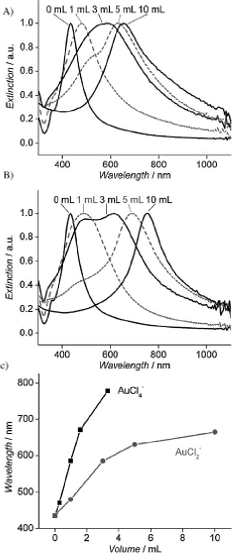
UV-vis spectra of the samples obtained by titrating Ag nanocubes with different volumes of 0.1 mm solution of A) AuCl2− and B) AuCl4−. C) Plot of the peak position versus the volume of gold precursor, suggesting that AuCl2− has a smaller shift (as seen by the more gradual ■OK?■ slope increase) compared to AuCl4− for the same volume of gold precursor added to the reaction solution.
Figure 4.
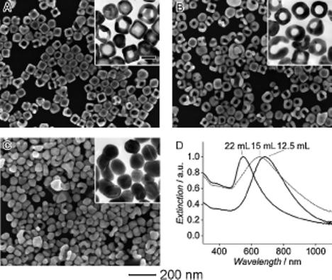
SEM and TEM (insets) images showing samples obtained in the later stages of the galvanic replacement reaction where Ag nanocubes were reacted with A) 12.5 mL, B) 15.0 mL, and (C) 22.0 mL of 0.1 mM AuCl2−. The scale bar in the inset in (A) represents 50 nm and applies to all TEM images. The corresponding UV-vis spectra of the products are shown in (D).
We also studied the late stages of the galvanic replacement reaction with AuCl2−. As reported in previous publications,[6] during the later stages of the galvanic replacement reaction with AuCl4− a dealloying process takes place, allowing Ag to be removed from the Au/Ag alloyed walls. The resultant lattice vacancies formed during the extraction of Ag atoms cause negative curvatures and, thus, an increase in interfacial area and surface energy for the solid walls.[14] This stress can be released by shape reconstruction, probably via an internal Oswald ripening process,[15] resulting in each corner of the nanobox being truncated to form a new face enclosed by the {111} crystallographic planes to lower the surface energy. A different reconstruction was observed for the later stages of the replacement reaction when AuCl2− was used as a precursor. As more AuCl2− solution was added to the suspension of nanoboxes with slightly truncated corners, the center of the faces became porous and nanoframes with edge length of 61±3 nm and thickness of about 17±2 nm were obtained (Fig. 3A and B, respectively). The formation of nanoframes contrasts with that of nanocages synthesized from the reaction with AuCl4−, and this difference in morphology is again related to the amount of Au(0) being deposited per each Ag(0) dissolved. In the case of AuCl4−, only one Au(0) atom is formed per every three Ag(0) atoms. As a result, the nanocages formed during the dealloying process have extremely thin edges, which quickly fall apart into discrete nanoparticles. On the other hand, AuCl2− generates one Au(0) atom per Ag(0) atom, thus making the edges of nanocages thicker and more robust to survive the dealloying process. Only when an extreme amount of AuCl2− solution was added (22 mL), regions of the nanoframes became globular and fragmented from the structures to form solid Au nanoparticles (Fig. 3A or Figure 4?■). The UV-vis spectra of these products show that the addition of AuCl2− blue-shifted the LSPR peak from 680 to 550 nm. Energy-dispersive X-ray (EDX) data showed that Ag was still present in the last sample, suggesting that the AuCl2− was unable to reach the Ag trapped inside the particle, thus, complete dealloying could not occur even with an excess of AuCl2−. In the case of AuCl4−, as more solution was added (5 mL) the dealloying process continued until essentially all the Ag in the alloyed walls was removed. In fact, the walls of the Au nanocages became so porous and fragile that the cages started to shatter into small pieces (Fig. S1). EDX measurements indicate that these fragments were made entirely from gold.
Table 1 summarizes the EDX data taken from the hollow nanostructures obtained at different stages of the reaction. Generally, the percentage of Au increased as more AuCl2− or AuCl4− solution was added into the reaction. At the early stages, the compositional increase of Au in the products obtained from the reactions with AuCl2− was higher than AuCl4−. This result is expected as more Au should be generated from the reaction with AuCl2− than with AuCl4− (at a 3:1 ratio) when the amount of oxidized Ag is held constant. However, at the late reaction stages, this trend is reversed. For example, when 10 mL of AuCl2− solution was added, the product was composed of 59% Au and 41% Ag, whereas for the product obtained from the reaction with 3.3 mL of AuCl4−, there was 72% Au and 28% Ag. These results confirm that more Ag can be removed via dealloying of the Au/Ag alloyed walls by AuCl4− than by AuCl2−.
Table 1.
The EDX percentages of gold, by weight, in the Au/Ag nanostructures obtained by titrating Ag nanocubes with different amounts of 0.1 mM AuCl2− or AuCl4−.
| AuCl2− | Au composition | AuCl4− | Au composition |
|---|---|---|---|
| [mL] | [wt %] | [mL] | [wt %] |
| 1.0 | 13 | 0.3 | 7 |
| 3.0 | 26 | 1.0 | 18 |
| 5.0 | 38 | 1.6 | 43 |
| 10.0 | 59 | 3.3 | 72 |
| 15.0 | 81 | 5.0 | 100 |
| 22.0 | 94 |
In summary, we have demonstrated that a change of stoichiometry between Au deposition and Ag oxidation in galvanic replacement reactions can lead to differences in the morphology, composition, and optical properties of the resultant hollow nanostructures. When Ag nanocubes were reacted with either AuCl4− or AuCl2−, nanoboxes with a hollow interior and a Au/Ag alloy shell were formed at the early stages of reaction. Thicker walls, however, were observed for the nanoboxes obtained from the reaction with AuCl2−. In later stages of replacement, AuCl4− dealloyed Ag from the walls of the Au/Ag alloy nanoboxes and formed porous nanocages. In contrast, the reaction with AuCl2− produces nanoframes, but AuCl2− did not completely dealloy Ag from the Au/Ag product even when excess AuCl2− solution was added. These differences observed in the course of hollow nanostructure formation can be attributed to differences in reaction stoichiometry, accomplished by simply using precursors with different oxidation numbers for gold. These results provide insight into the mechanism for hollow nanostructure formation via the galvanic replacement reaction, which is proving to be a versatile method for synthesizing these nanostructures as well as tuning their LSPR peaks for use in controlled release of drugs, optical sensing, and photothermal therapy.
Experimental
Synthesis of Ag Nanocubes
Silver nanocubes were prepared using the sulfide-mediated polyol process as described in a previous publication [10]. In a typical synthesis, ethylene glycol (EG, 6 mL, J.T. Baker, 9300−03) was preheated to 155 °C for 1 h under magnetic stirring. EG solutions containing Na2S (3 mm, Aldrich, 208043), poly(vinyl pyrrolidone) (PVP, 0.18 m, MW ∼55000, Aldrich, 856568, the concentration was calculated in terms of the repeating units), and AgNO3 (0.28 m, Aldrich, 209139) were prepared. The Na2S solution (80 μL) was injected into the hot EG, followed by the PVP solution (1.5 mL) and AgNO3 solution (0.5 mL). The reaction underwent color changes from yellow to reddish brown to opaque brown within 10 min. The sample was washed with acetone and then twice with deionized water. After washing, the product was collected by centrifugation at 132000 rpm for 5 min and then redispersed by brief sonication in deionized water (4 mL).
Synthesis of Ag/Au Nanocages using AuCl2−
In a typical synthesis, a fixed amount of silver nanocubes (ca. 3.5 nm, 50 μL) was dispersed in deionized water (5 mL) containing PVP (1 mg mL−1) in a 50 mL flask under magnetic stirring and then heated to boil for 10 min. In the meantime, a NaCl (J.T. Baker, 362401) saturated aqueous solution of AuCl (0.1 mm, Aldrich, 481130) was prepared. (Note: to avoid contamination of Au(III), AuCl was washed three times with chloroform to remove Au(III) and thoroughly dried in the vacuum prior to usage.) A specific amount (as indicated in the text) of the NaCl-saturated AuCl was added to the flask through a two-channel syringe pump (KDS-200, Stoelting, Wood Dale, IL) at a rate of 45 mL h−1 under magnetic stirring. The solution was heated for another 10 min until the color of the reaction was stable. Once cooled to room temperature, the sample was centrifuged and washed with saturated NaCl solution to remove AgCl and with water several times to remove PVP and NaCl before characterization by SEM and TEM.
Synthesis of Ag/Au Nanocages using AuCl4−
In a typical synthesis, a fixed amount of silver nanocubes (ca. 3.5 nm,50 μL) was dispersed in deionized water (5 mL) containing PVP (1 mg mL−1)in a 50 mL flask under magnetic stirring and then heated to boil for 10 min. In the meantime, an aqueous solution of HAuCl4 (0.1 mm, Aldrich, 520918) was prepared. A specific amount (as indicated in the text) of HAuCl4 was added to the flask through a two-channel syringe pump (KDS-200, Stoelting, Wood Dale, IL) at a rate of 45 mL h−1 under magnetic stirring. The solution was heated for another 10 min until the color of the reaction was stable. Once cooled to room temperature, the sample was centrifuged and washed with saturated NaCl solution to remove AgCl and with water several times to remove PVP and NaCl before characterization by SEM and TEM.
Instrumentation
SEM (or TEM) samples were prepared by placing a drop of the final product (suspended in water) on a silicon wafer (or carbon-coated copper grid) and drying under ambient conditions. SEM images were taken using a Sirion XL field-emission microscope (FEI, Hillsboro, OR) operated at an acceleration voltage of 10 kV. EDX measurements were conducted with the EDX system attached to the same microscope. TEM imaging was performed using a Phillips CM100 microscope operated at 100 kV. The UV-vis spectra were obtained using a Cary 50 UV-vis spectrophotometer (Varian, Palo Alto, CA).
Footnotes
This work was supported in part by a Director's Pioneer Award from the NIH (1DPOD000798) and a research grant from the NSF (DMR-0451788). Y.X. is a Camille Dreyfus Teacher Scholar (2002−2007). L.A. thanks the Center for Nanotechnology at the UW for an IGERT Fellowship funded by the NSF and NCI. We thank Dr. Sara Skrabalak for her critical reading of this manuscript. Supporting Information is available online from Wiley InterScience or from the author.
Contributor Information
Leslie Au, Department of Chemistry University of Washington Seattle, WA 98195 (USA).
Xianmao Lu, Department of Biomedical Engineering Washington University in St. Louis Saint Louis, MO 63130 (USA) E-mail: xia@biomed.wustl.edu.
Younan Xia, Department of Biomedical Engineering Washington University in St. Louis Saint Louis, MO 63130 (USA).
References
- 1.a Chen J, Wiley B, McLellan J, Xiong Y, Li Z-Y, Xia Y. Nano Lett. 2005;5:2058. doi: 10.1021/nl051652u. [DOI] [PubMed] [Google Scholar]; b Lu X, Chen J, Skrabalak SE, Xia Y. P. I. Mech. Eng. N-J. Nanoeng. Nanosys. 2007;221 in press ■Update? Please specify journal name.■. [Google Scholar]; c Cobley CM, Campbell DJ, Xia Y. Adv. Mater. 2008;20:748. doi: 10.1002/adma.200702501. [DOI] [PMC free article] [PubMed] [Google Scholar]
- 2.Lu X, Au L, McLellan J, Li Z-Y, Marquez H, Xia Y. Nano Lett. 2007;7:1764. doi: 10.1021/nl070838l. [DOI] [PMC free article] [PubMed] [Google Scholar]
- 3.Portney NG, Ozkan M. Anal. Bioanal. Chem. 2006;384:620. doi: 10.1007/s00216-005-0247-7. [DOI] [PubMed] [Google Scholar]
- 4.a Chen J, Saeki F, Wiley BJ, Cang H, Cobb MJ, Li Z-Y, Au L, Zhang H, Kimmey MB, Li X, Xia Y. Nano Lett. 2005;5:473. doi: 10.1021/nl047950t. [DOI] [PubMed] [Google Scholar]; b Chen J, Wiley BJ, Li Z-Y, Campbell D, Saeki F, Cang H, Au L, Lee J, Li X, Xia Y. Adv. Mater. 2005;17:2255. [Google Scholar]; c Cang H, Sun T, Li Z-Y, Chen J, Wiley BJ, Xia Y, Li X. Opt. Lett. 2005;30:3048. doi: 10.1364/ol.30.003048. [DOI] [PubMed] [Google Scholar]
- 5.a Loo C, Lin A, Hirsch L, Lee MH, Barton J, Halas N, West J, Drezek R. Technol. Cancer Res. Treat. 2004;3:33. doi: 10.1177/153303460400300104. [DOI] [PubMed] [Google Scholar]; b Chen J, Wang D, Xi J, Au L, Siekkinen A, Warsen A, Li Z-Y, Zhang H, Xia Y, Li X. Nano Lett. 2007;7:1318. doi: 10.1021/nl070345g. [DOI] [PMC free article] [PubMed] [Google Scholar]; c Hirsch LR, Gobin AM, Lowery AR, Tam F, Drezek RA, Halas NJ, West JL. Ann. Biomed. Eng. 2006;34:15. doi: 10.1007/s10439-005-9001-8. [DOI] [PubMed] [Google Scholar]
- 6.a Sun Y, Xia Y. Science. 2002;298:2176. doi: 10.1126/science.1077229. [DOI] [PubMed] [Google Scholar]; b Sun Y, Mayer B, Xia Y. Nano Lett. 2002;2:481. [Google Scholar]; c Sun Y, Xia Y. Nano Lett. 2003;3:1569. [Google Scholar]; d Sun Y, Wiley B, Li Z-Y, Xia Y. J. Am. Chem. Soc. 2004;126:9399. doi: 10.1021/ja048789r. [DOI] [PubMed] [Google Scholar]
- 7. The reduction potentials reported in this manuscript are referenced to the SHE at 25 °C, 1 atm; however, the galvanic replacement reactions discussed here are performed at elevated temperatures under unique conditions, thus, the absolute electrochemical potential difference could deviate from that reported. With the relatively high concentration of Cl− present during the galvanic replacement, we suggest that at the site of reaction AgCl nanocrystallites are formed that then dissolve into the bulk solvent at the elevated reaction temperature.
- 8.Sun Y, Xia Y. J. Am. Chem. Soc. 2004;126:3892. doi: 10.1021/ja039734c. [DOI] [PubMed] [Google Scholar]
- 9.Qian L, Yang X. Colloids Surf. A. 2005;260:79. [Google Scholar]
- 10.a Siekkinen AR, McLellan JM, Chen J, Xia Y. Chem. Phys. Lett. 2006;432:491. doi: 10.1016/j.cplett.2006.10.095. [DOI] [PMC free article] [PubMed] [Google Scholar]; b Skrabalak SE, Au L, Li X, Xia Y. Nat. Protoc. 2007;2:2182. doi: 10.1038/nprot.2007.326. [DOI] [PubMed] [Google Scholar]
- 11.Dick K, Dhanasekaran T, Zhang Z, Meisel D. J. Am. Chem. Soc. 2002;124:2312. doi: 10.1021/ja017281a. [DOI] [PubMed] [Google Scholar]
- 12.Shi H, Zhang L, Cai W. J. Appl. Phys. 2000;87:1572. [Google Scholar]
- 13.a Yin Y, Rioux R, Erdonmez C, Hughes S, Somorjai G, Alivisatos AP. Science. 2004;304:711. doi: 10.1126/science.1096566. [DOI] [PubMed] [Google Scholar]; b Yin Y, Erdonmez C, Cabot A, Hughes S, Alivisatos AP. Adv. Funct. Mater. 2006;16:1389. [Google Scholar]; c Fan HJ, Knez M, Scholz R, Hesse D, Nielsch K, Zacharias M, Gosele U. Nano. Lett. 2007;7:993. doi: 10.1021/nl070026p. [DOI] [PubMed] [Google Scholar]
- 14.Sieradzki K. J. Electrochem. Soc. 1993;140:2868. [Google Scholar]
- 15.Roosen AR, Carter WC. Phys. A. 1998;261:232. [Google Scholar]
- 16.Chen J, McLellan J, Siekkinen A, Xiong Y, Li Z-Y, Xia Y. J. Am. Chem. Soc. 2006;128:14776. doi: 10.1021/ja066023g. [DOI] [PMC free article] [PubMed] [Google Scholar]