Abstract
We have developed a new approach to detect mechanical forces exerted by locomoting fibroblasts on the substrate. Cells were cultured on elastic, collagen-coated polyacrylamide sheets embedded with 0.2-μm fluorescent beads. Forces exerted by the cell cause deformation of the substrate and displacement of the beads. By recording the position of beads during cell locomotion and after cell removal, we discovered that most forces were radially distributed, switching direction in the anterior region. Deformations near the leading edge were strong, transient, and variable in magnitude, consistent with active local contractions, whereas those in the posterior region were weaker, more stable, and more uniform, consistent with passive resistance. Treatment of cells with cytochalasin D or myosin II inhibitors caused relaxation of the forces, suggesting that they are generated primarily via actin–myosin II interactions; treatment with nocodazole caused no immediate effect on forces. Immunofluorescence indicated that the frontal region of strong deformation contained many vinculin plaques but no apparent concentration of actin or myosin II filaments. Strong mechanical forces in the anterior region, generated by locally activated myosin II and transmitted through vinculin-rich structures, likely play a major role in cell locomotion and in mechanical signaling with the surrounding environment.
INTRODUCTION
Interactions between cells and their environment involve not only chemical signals but also mechanical forces. The latter is believed to provide the driving force for cell locomotion; to move forward, cells must adhere to the substrate and exert rearward traction forces (Oliver et al., 1994; Lauffenburger and Horwitz, 1996). In addition, there is strong evidence that mechanical interactions can modulate a wide spectrum of cellular processes from locomotion to differentiation (Ingber, 1993). Our recent observations with substrates of different flexibility further suggest that such modulation involves not only responses to external forces but active probing of the mechanical properties of the environment (Pelham and Wang, 1997).
Despite rapid advances in the characterization of motor and adhesion molecules, little is known about the nature of mechanical forces exerted by the cell and the mechanism for translating them into downstream events such as coordinated cell movement. The first successful attempt in detecting mechanical forces was reported by Harris et al. (1980), using a thin film of silicone rubber as the culturing substrate. The film covers a layer of silicone fluid and wrinkles upon the exertion of forces much like the response of a water bed. Using this method, Harris et al. (1980) discovered significant compressive forces exerted by locomoting fibroblasts. However, despite recent improvement of the material (Burton and Taylor, 1997), the approach suffers from a limited spatial resolution and complex relationship between wrinkles and forces.
Two approaches have been developed toward a more direct characterization of cellular traction forces. The first involves the use of nonwrinkling silicone polymers embedded with particles as indicators of deformation (Lee et al., 1994). This approach has yielded detailed vectorial maps of mechanical forces under fish keratocytes (Oliver et al., 1995; Dembo et al., 1996). Although it represents a significant improvement over the wrinkling method, there are potential limitations that could affect its application to cultured fibroblasts. First, the viscous component of the material could lead to irreversible deformation when exerted with forces over a prolonged period of time by slow-moving cells such as fibroblasts (Lee et al., 1994). In addition, uncoated silicone sheets are poorly adhesive for fibroblasts and may affect the generation of traction forces (Harris, 1988). A related method involves the use of collagen matrices embedded with beads (Roy et al., 1997). Although the chemical property of the substrate was optimized for cell adhesion, the study was limited by the optical resolution and by the irreversible deformation of the substrate. A second approach uses microfabricated silicon substrates that contain islands of miniature pads connected to flexible cantilevers. Forces are measured on the basis of the movement of these pads (Galbraith and Sheetz, 1997). Fluctuating forces, which switch the direction from rearward to forward under the nucleus, were detected under locomoting chick embryonic fibroblasts. Although this method allows measurements of forces in isolated regions, it has a limited spatial resolution and provides little information on the direction of forces.
In the present study we seek to complement these studies by using a different approach, based on a flexible polyacrylamide substrate embedded with fluorescent latex beads. The approach is similar to that used by Lee et al. (1994); however the substrate is easy to prepare, has a controllable and nearly ideal elastic property (see RESULTS), and, when covalently coated with extracellular matrix proteins, provides a more physiological environment for cell adhesion. Moreover, the clarity and stability of the material allowed us to examine the distribution of vinculin, actin, and myosin by immunofluorescence in relation to exerted mechanical forces. As a first step we have focused on qualitative aspects of the forces exerted by moving 3T3 fibroblasts and the corresponding cytoskeleton organization. Quantitative analysis of the forces by computer modeling will be presented in a separate report (Dembo and Wang, 1999).
MATERIALS AND METHODS
Polyacrylamide Substrate
The polyacrylamide substrate was prepared essentially as described previously (Pelham and Wang, 1997; Wang and Pelham, 1998). The only modifications were the reduction in concentration of Sulfo-SANPAH (Pierce Chemical, Rockford, IL) to 1 mM and of HEPES to 50 mM and the addition of sonicated fluorescent latex beads (0.2-μm FluoSpheres, carboxylate-modified; Cat. No. F-8821, Molecular Probes, Eugene, OR) at 1:125 dilution to the acrylamide mixture containing 10% acrylamide and 0.03% bis-acrylamide. The flexibility of the substrate was characterized by deforming sheets with known weights and with a microneedle. Briefly, 18.5 g of weight was applied to a 14 × 14 × 0.7-mm sheet of polyacrylamide, and the change in thickness was measured with the microscope-focusing mechanism. Young’s modulus was calculated according to the equation: Y = (F⊥/A)/(Δl/l), where l is the original thickness of the sheet, Δl is the change in thickness, and A is the cross-sectional area. The response of the substrate to prolonged deformation was assessed by submerging gel strips 70 mm × 30 mm × 1 mm in a tank filled with PBS at room temperature and stretching some of them for 17.5 h with 10 g of weight. The extent of recovery was determined by comparing the length of a stretched strip with that of an unstretched strip submerged for the same period of time. Deformation with microneedles was performed as described by Lee et al. (1994).
Measurements of Substrate Deformation
Deformation of the substrate by cell-generated forces was detected via the displacement of embedded beads. Images of beads near the surface of the substrate (described in Fixation, Fluorescent Staining, and Microscopy) were recorded before and after the detachment of cells (and relaxation of forces) with 0.05% trypsin. The pair of images was registered on the basis of beads located far away from the cell. The coordinates of each bead before and after trypsin treatment were determined using custom written software and were plotted as a vectorial map. Substrate deformation during cell movement was detected by illuminating cells simultaneously for phase and fluorescence optics. Tracks of bead movement were generated by importing the coordinates into Microsoft (Redmond, WA) Excel.
Cell Culture and Drug Treatments
Swiss 3T3 cells (American Type Culture Collection, Rockville, MD) were cultured in DMEM (Sigma, St. Louis, MO), supplemented with 10% donor calf serum (JRH Biosciences, Lenexa, KS), 2 mM l-glutamine, 50 μg/ml streptomycin, 50 U/ml penicillin, and 250 ng/ml amphotericin B (Life Technologies, Gaithersburg, MD). KT5926 (Calbiochem, San Diego, CA), nocodazole (Sigma), and cytochalasin D (Sigma) were each dissolved in DMSO to obtain stock solutions of 2, 33, and 2 mM, respectively. Immediately before drug treatments, aliquots of stock solutions were diluted into serum-containing media to obtain a final concentration of 20 μM for KT5926, 1 μM for nocodazole, and 2 μM for cytochalasin D. 2,3-Butanedione monoxime (BDM; Sigma) was dissolved directly in culture medium to generate a working solution at a final concentration of 20 mM.
Fixation, Fluorescent Staining, and Microscopy
For fluorescent staining of vinculin and myosin, cells were washed with 37°C PBS and then simultaneously fixed and extracted with 4% formaldehyde and 0.1% Triton X-100 (Boehringer Mannheim, Mannheim, Germany) in PBS at 37°C for 10 min as described previously (Pelham et al., 1996). Immunofluorescence staining was performed using monoclonal antibodies against vinculin (clone VIN-11-5, Sigma) or polyclonal antibodies against platelet myosin II (generously provided by Dr. Keigi Fujiwara, National Cardiovascular Center Research Institute, Osaka, Japan), each at a dilution of 1:100. Rhodamine- and fluorescein-conjugated secondary antibodies were obtained from Sigma.
For fluorescent staining of actin, cells were fixed and permeabilized with 0.1% Triton X-100 and 0.5% glutaraldehyde (Polysciences, Warrington, PA) in cytoskeleton buffer [137 mM NaCl, 5 mM KCl, 1.1 mM Na2HPO4, 0.4 mM KH2PO4, 2 mM MgCl2, 2 mM EGTA, 5 mM piperazine-N,N′-bis(2-ethanesulfonic acid), and 5.5 mM glucose, pH 6.1 (Small, 1981)] at 37°C for 1 min and then post-fixed with 1% glutaraldehyde in 37°C cytoskeleton buffer for 15 min. After treatment with 0.5 mg/ml NaBH4 for 5 min to quench autofluorescence, cells were stained with rhodamine–phalloidin (Molecular Probes) at a concentration of 6.6 nM.
Phase images of the cell and fluorescence of substrate-embedded beads were recorded simultaneously with a Zeiss 40×, numerical aperture 0.65 Achromat phase objective on a Zeiss (Thornwood, NY) IM-35 microscope. The depth of field was ∼5 μm; thus most beads recorded were located within the top 2.5 μm of the substrate. A Nikon (Garden City, NY) 60×, numerical aperture 1.2 PlanApo water immersion objective was used in conjunction with a Zeiss Axiovert microscope for the observation of immunofluorescence staining of cells. All images were recorded with a cooled charge-coupled device camera (TE/CCD-576EM, Princeton Instruments, Trenton, NJ, or CH250, Photometrics, Tucson, AZ) and processed for background subtraction with custom software.
RESULTS
Characterization of Polyacrylamide Substrate
Mechanical forces exerted by locomoting 3T3 fibroblasts were detected by culturing cells on a highly flexible substrate and measuring deformation of the substrate. The substrate was prepared by incorporating 0.2-μm fluorescent latex beads into thin polyacrylamide sheets of 10% acrylamide and 0.03% bis-acrylamide, followed by covalent coating of the surface with type I collagen to promote cell adhesion (Pelham and Wang, 1997; Wang and Pelham, 1998). As reported recently (Pelham and Wang, 1997), 3T3 cells adhere well on these substrates and migrate at an accelerated rate of 0.55 μm/min.
Mechanical properties of the substrate were characterized both macroscopically and microscopically (Lee et al., 1994). The substrate responded to applied forces with a Young’s modulus of 6000 N/m2 and recovered within 1/30 s (one video frame) upon the release of forces. When probed with a calibrated microneedle, the response remained proportional to the force when the substrate was deformed by up to ∼20 μm, with no apparent heterogeneity in elasticity. In addition, the recovery was complete (>98%) even when the substrate was stretched by ∼90% for >17 h. Because of the propagation of deformations across the surface, exact values of forces cannot be obtained without complicated computer modeling (Dembo et al., 1996; Dembo and Wang, 1999). However qualitative characteristics of cell-generated mechanical forces become clear as one examines the pattern of deformations. Computer modeling indicates that this approach provides a spatial resolution of ∼5 μm (Dembo and Wang, 1999).
Distribution of Mechanical Forces under Locomoting Cells
We first examined the overall pattern of deformation exerted by locomoting 3T3 cells. Isolated cells and beads in the vicinity were observed for 30 min with time-lapse recording to determine the rate and direction of locomotion. The dish was then treated with trypsin to detach the cells and relax the forces generated by the cell. Cell-induced displacements of fluorescent beads were then used to construct a vectorial map of substrate deformation, which provides a qualitative indication of the distribution of forces (Lee et al., 1994).
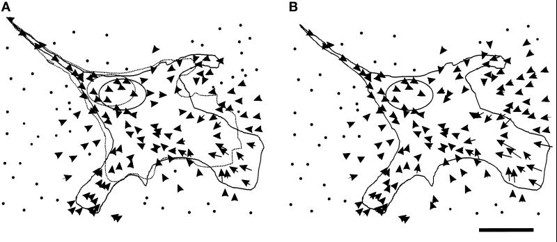
In all cells observed, substrate deformation showed a radial pattern (Figure 1B; n = 31), even when cells were moving along a fixed direction. In addition, all cells showed a switch in deformation from a direction opposite of cell locomotion to a direction along cell locomotion in the anterior lamella region. Thus most forces near the leading edge were directed rearward, whereas those under the posterior region were directed forward. The strongest deformations were always detected within 5–15 μm of active ruffling and were heterogeneous in magnitude and direction (Figure 1B), suggesting that forces in this region are highly variable over short distances. Moreover, strong deformations were present in only some active areas and thus did not seem to be a prerequisite for cell protrusion. The maximal deformation was ∼5 μm.
Figure 1.
Distribution of substrate deformation caused by a motile 3T3 cell. (A) The dotted line represents the cell boundary at t = 0 min, and the solid line represents the cell boundary at t = 30 min. Arrows show changes in the position of substrate-embedded beads as the cell migrated forward during this period of time. (B) At t = 30 min, the cell was detached from the substrate with trypsin. Arrows were constructed from the bead positions after cell detachment to those before detachment and reflect the net forces exerted by the cell. To facilitate plotting, the scale of the arrows was amplified twice relative to the scale of the cell (this also applies to all subsequent figures). The arrows show a radial pattern converging in a region just in front of the nucleus. Bar, 20 μm.
Deformations in the posterior region were in general smaller and more uniform in magnitude (Figure 1B). A small number of cells showed a localized increase in deformation at the very tail, possibly reflecting transient tail contraction before the retraction of the cell (Chen, 1979). However tail retractions are rarely captured directly with live 3T3 fibroblasts.
Dynamics of Mechanical Forces Generated by Locomoting Cells
The dynamics of mechanical forces generated by locomoting 3T3 cells were investigated by time-lapse recording of beads embedded in the substrate (Figure 1A). Unlike the previous experiment, translocation of beads reflects temporal changes in substrate deformation (thus changes in the magnitude or direction of forces exerted by the cell) rather than net mechanical forces.
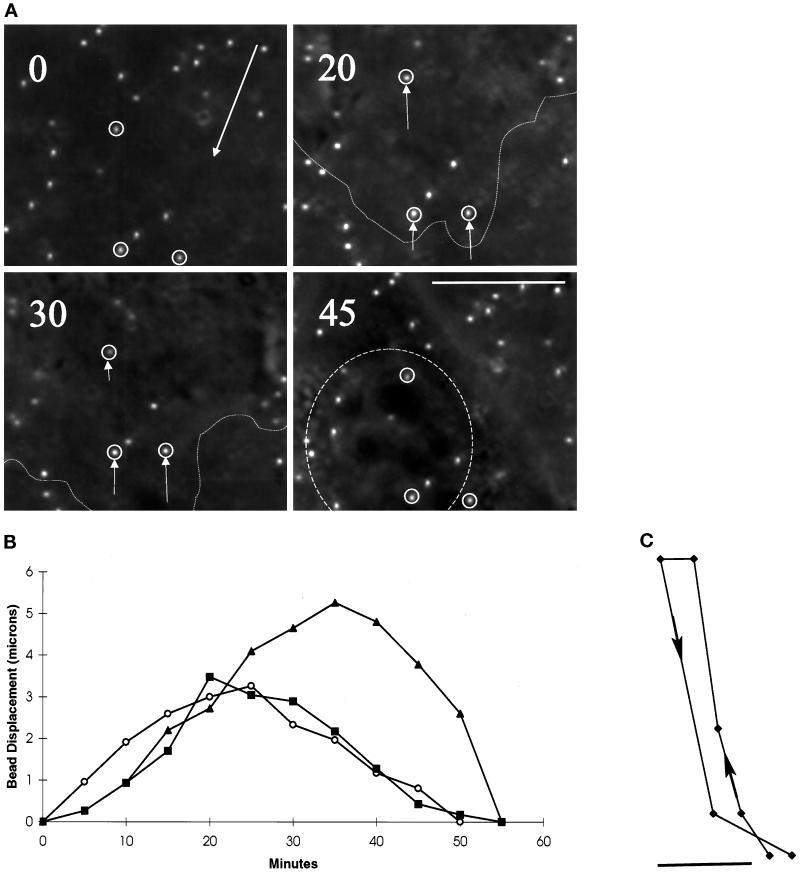
As the leading edge of a cell approached a bead, strong rearward movement of beads developed (Figures 1A and 2, A and B). The deformation increased with time and reached a maximum in ∼30 min (Figure 2B) and then dissipated over the next ∼30 min during which the anterior region of the cell migrated over the bead. These observations suggest that new forces are continuously generated at the leading edge. Although the magnitude of deformation changed continuously, the movement of the beads followed a smooth course (Figure 2C), indicating that there is no rapid fluctuation of forces as a function of time.
Figure 2.
Changes in substrate deformation in the anterior region of motile cells. (A) The movement of substrate-embedded beads under the anterior portion of a motile cell was recorded at the time (in minutes) indicated in the top left corner. Small arrows indicate the positions of the several beads relative to their neutral positions at t = 0. The direction of cell movement is indicated by a large arrow at t = 0. The boundary of the cell is indicated by a dotted line at t = 20 and 30 min. The position of the nucleus is indicated by a dashed circle at t = 45 min. Strong deformation developed in a region ∼5–10 μm from the active leading edge and dissipated as the nucleus moved over the beads. Bar, 10 μm. (B) The magnitude of substrate deformation is plotted as a function of time for three beads from three different locomoting cells. The deformation reached its maximum in ∼25 min and then dissipated over the next ∼30 min without showing a measurable plateau. (C) The track of a bead moving under the anterior region of a cell follows a smooth course, with no detectable fluctuation in direction. Bar, 1 μm.
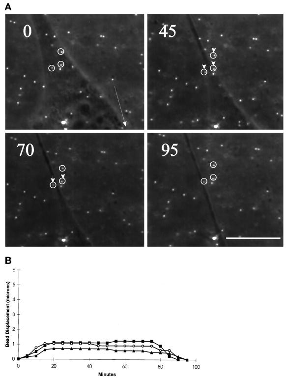
As the nucleus passed over the bead, a slow net forward translocation of the bead started, as if the beads were dragged by the cell in the direction of locomotion (Figures 1A and 3A). Unlike deformations in the anterior region, deformations in the posterior region remained at a weak constant value for an extended period of time (Figure 3B), indicating that mechanical forces were relatively stable and uniform. After the tail passed the bead, contact between the cell and substrate was lost, and the bead returned to its basal position (Figure 3A).
Figure 3.
Changes in substrate deformation in the posterior region of motile cells. (A) The movement of substrate-embedded beads under the posterior portion of a motile cell was recorded at the time (in minutes) indicated in the top left corner. Small arrows indicate the positions of the several beads relative to their positions at t = 0. The direction of cell movement is indicated by a large arrow at t = 0. Weak deformation developed in the tail region and was maintained until the cell migrated away from the beads. Bar, 10 μm. (B) The magnitude of substrate deformation is plotted as a function of time for three beads from three different locomoting cells. The deformation reached its plateau in ∼20 min and was maintained at a low, constant level for 50–60 min until the cell moved beyond the beads.
Role of the Cytoskeleton in Generating Mechanical Forces
To probe the role of cytoskeletal structures in generating mechanical forces, we applied various agents to disrupt actin, myosin, or microtubules. Cells (and underlying beads) were observed in the presence of these inhibitors for 30 min to determine drug-induced changes in deformation and then were trypsinized to construct a vectorial map of substrate deformation at steady state.
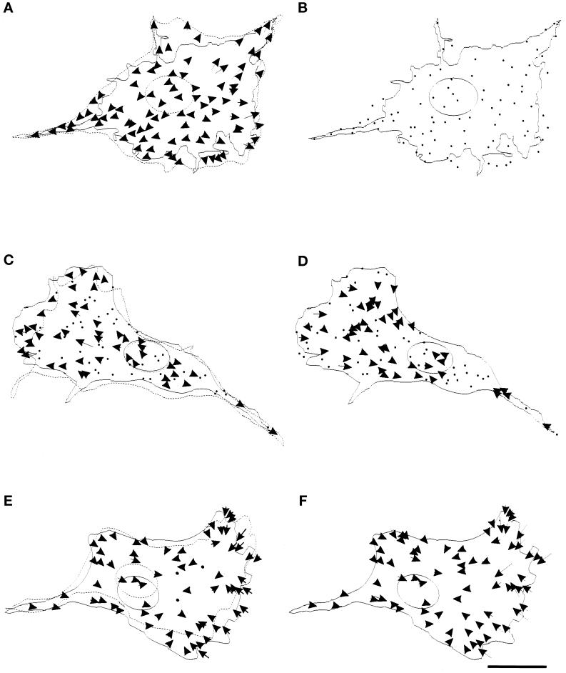
Dramatic effects were observed after the treatment with 2 μM cytochalasin D. The beads moved immediately away from the nucleus toward their neutral positions (Figure 4A; n = 5), such that no substrate deformation was detectable upon trypsinization (Figure 4B). KT5926, an inhibitor of myosin light chain kinase (Nakanishi et al., 1990), also caused a dramatic, but less complete (80–90%), reduction in both rearward and forward forces (Figure 4, C and D; n = 6). Interestingly, both lamellipodial protrusion and forward movement of the cell persisted during the period of observation in KT5926, whereas the rate of nuclear movement decreased by ∼74%. Treatment with myosin inhibitor BDM (Higuchi and Takemori, 1989) had similar, although weaker, effects (our unpublished results). The role of microtubules in generating and/or directing motile forces was investigated by treating cells with the microtubule-depolymerizing drug nocodazole (Figure 4, E and F; n = 6). The treatment caused no apparent change in the overall pattern of substrate deformation over 30 min, when most or all microtubules depolymerized as judged by immunofluorescence.
Figure 4.
Effects of drugs on mechanical forces generated by the cell. (A) A cell and beads in the underlying substrate were observed in the presence of 2 μM cytochalasin D for 30 min. The cell stopped forward movement and retracted its boundary (from dotted to solid line), while all the beads moved away from the center of the cell, suggesting the relaxation of forces throughout the cell. (B) The cell was then detached by trypsin to detect any residual deformation at steady state. No bead movement was detected. The dots represent the stationary positions of the beads. (C–F) Similar experiments were performed with 20 μM KT5926 (C and D) and 1 μM nocodazole (E and F). A fraction of thebeads moved away from the center of the cell upon treatment with KT5926, as shown by arrows (C), while others maintained their positions, as shown by dots. No newly developed inward force was detected. The rate of forward movement of the nucleus was reduced by 75% (from dotted to solid line), while the protrusion of the leading edge appeared similar to that in control cells. The forces maintained a radial pattern as in control cells but with an average magnitude reduced by 80–90% (D). Nocodazole had no apparent effect on the overall pattern of forces as compared with that in control cells (E and F). Bar, 20 μm.
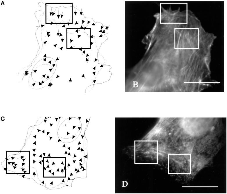
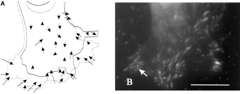
Immunofluorescence staining was performed to determine whether there is any specific structure of actin, myosin, or vinculin in the region of new strong forces. No prominent concentration of actin and myosin was detected in these regions (Figure 5), although they often contained converging actin filament bundles. In addition, vinculin immunofluorescence showed many elongated adhesion structures in these regions (Figure 6).
Figure 5.
Distribution of actin filaments and myosin II in relation to strong substrate deformations in the anterior region. (A and C) Cells and beads in the underlying substrate were observed for 20 min. Movements of the beads are indicated by arrows. Dotted and solid lines indicate the starting and ending positions, respectively, of the cell boundary and nucleus. (B and D) The cells were then fixed and stained with rhodamine–phalloidin (B) or antibodies against myosin II (D) to determine the relationship between actin–myosin II organization and mechanical forces. Actin filaments are distributed similarly in areas of large and small substrate deformations (A and B, rectangles). Fine actin bundles are present throughout most regions of the cell. In addition, the concentration of myosin II was similar in regions of strong and weak forces (C and D, rectangles). Bars, 20 μm.
Figure 6.
Distribution of vinculin in relation to large substrate deformations in the anterior region. (A) A cell and beads in the underlying substrate were observed for 12 min. Movements of the beads are indicated by arrows. Solid and dotted lines indicate the starting and ending positions, respectively, of the cell boundary and nucleus. (B) The cell was then fixed and immunofluorescence stained for vinculin to determine the relationship between vinculin organization and mechanical forces. Vinculin is concentrated at elongated plaque structures in the region of strong mechanical forces (B; arrow). Bar, 20 μm.
DISCUSSION
We have used a new approach to detect mechanical forces generated by locomoting fibroblasts. Our method, based on particle movement within an elastic substrate, has several important advantages. First, the approach allows for the global mapping of substrate deformations resulting from cell-generated traction forces. Although complex computation and modeling are required to obtain exact force values (Dembo et al., 1996; Dembo and Wang, 1999), the combination of time-lapse recording and cell trypsinization provides a rapid glimpse into the qualitative characteristics of cell-generated mechanical forces. Second, the polyacrylamide material has a nearly ideal elastic property that can be adjusted by changing the concentrations of acrylamide and bis-acrylamide (Pelham and Wang, 1997; Wang and Pelham, 1998). This allows us to match the sensitivity of the substrate with the strength of forces generated by different cell types. Third, the substrate, which is typically <70 μm in thickness, has an excellent optical quality and allows fluorescence microscopy at a high magnification. The chemical property can also be varied via the conjugation of different extracellular matrix molecules to mimic the physiological environment.
Characteristics of Cell-generated Mechanical Forces
Mechanical forces exerted by locomoting 3T3 fibroblasts show several interesting characteristics. First, the forces are radially distributed, shifting directions in a region in front of the nucleus. In addition, strong traction forces are present in some but not all regions of active protrusion. Thus the pattern of forces seems to be closely related to the shape of the cell and the direction of cell movement, but not necessarily coupled to cell protrusion at lamellipodia. The radial pattern may also be related to the predominantly lateral orientation of forces in fish keratocytes, which have a fan shape with the long axis lying perpendicular to the direction of locomotion (Lee et al., 1994). As in the present case, the strongest forces were found near the ends of the long dimension and pointed toward the nucleus.
Second, the strongest deformation was always detected near the leading edge, consistent with observations made with wrinkling substrates (Harris et al., 1980). Our results are however contrary to those obtained with microfabricated silicon pads connected to flexible cantilevers (Galbraith and Sheetz, 1997), which detected opposite forces in the front and tail regions but with stronger forces located near the tail. However, the pads detect forces only along one direction, with a resolution limited by the dimension and distance of the pads (2 × 2- to 5 × 5-μm2 area and 60-μm center-to-center distance between neighboring pads). Moreover, the unique topographical feature of the surface, with adhesive pads surrounded by regions of nonadhesive space, may also elicit unique cellular responses (Chen et al., 1997).
Third, rearward bead displacements near the leading edge are strong, transient, and heterogeneous over a short distance, suggesting that the forces involved are generated by an active mechanism that varies in magnitude or direction over a short distance. In contract, forward bead displacements in the posterior region are weak, stable, and more uniform. They become apparent upon the passage of the nucleus and stay at a low level until the cell moves away from the substrate. This pattern is consistent with a passive, forward drag generated over broad areas of the surface during cell movement (Oliver et al., 1994, and references within; Cramer et al., 1997).
Mechanisms for the Generation of Mechanical Forces
Our immunofluorescence localization of vinculin showed clusters of elongated adhesion sites in the region of strong rearward forces. Most likely these forces are transmitted to the substrate at or near vinculin-rich adhesion structures. In addition, the forces are likely generated by actin–myosin II contractions, as indicated by their sensitivity to cytochalasin D, BDM, and KT5926. Using computer modeling, we found that the forces have a maximal magnitude of 10 nN/μm2 (Dembo and Wang, 1999), or ∼104 active myosin heads per square micrometer, assuming that each myosin head generates ∼1 pN of force (Ishijima et al., 1991; Oliver et al., 1995; Dembo et al., 1996). The lack of apparent concentration of myosin II at the site of strong substrate deformation suggests that these forces may be generated over large regions of the cell and focused into discrete sites of adhesion or may involve additional mechanisms. In addition, forces may be maintained by a latch mechanism without the continuous interactions of actin and myosin. The leading edge is also known for a continuous assembly and backward flux of actin subunits (Wang, 1985). Traction forces may be generated via mechanical linkage of these actin filaments to the adhesion sites.
On the basis of the radial pattern of the forces, which converge in a region occupied by the microtubule-organizing center, we speculate that the forces may involve either contributions from microtubule motors or guidance by the microtubule network. However, direct involvement of microtubules and microtubule motors is unlikely because of the lack of immediate effects after the depolymerization of microtubules by nocodazole, although it is possible that forces may be affected after a longer period of microtubule depolymerization. Unlike previous studies, cells cultured under our condition showed no apparent increase in stress fibers upon the depolymerization of microtubules (Danowski, 1989; Bershadsky et al., 1996).
Functional Role of Cell-generated Mechanical Forces
To effect forward locomotion, cell–substrate adhesions may function either as passive sites of anchorage, to keep cells from slipping backward during the forward thrust of the leading edge, or as active sites of propulsion, where motor molecules drive the forward movement of the cortex and/or intracellular contents. The active characteristics of rearward forces, as discussed above, are more consistent with the latter model. In addition, the distribution of substrate deformation suggests that such traction forces are concentrated near the leading edge of the cell. Because of the propagation of deformation, the actual boundary of strong traction forces is likely to be located closer to the front than what is shown in the present map (Dembo and Wang, 1999). Together, these results indicate that fibroblasts migrate by a frontal contraction mechanism, which exerts traction forces near the leading edge. Contraction at the tail is probably responsible for maintaining the integrity of the cell but not directly for the forward movement.
However, although strong rearward forces are always located near an active leading edge (Figure 1), there are regions of lamellipodial extension without apparent strong forces. The radial pattern of these forces also does not support a direct role in forward thrust of the cell. In addition, the magnitude of such forces appears many orders of magnitude stronger than what is required to overcome the fluid and surface resistance during steady cell locomotion (Harris et al., 1981; Oliver et al., 1994), consistent with the continuous movement of the cell when most forces were inhibited by KT5926. An alternative role for the rearward forces is to drive large intracellular structures, such as the nucleus and the microtubule/intermediate filament networks. The forward positioning of the nucleus and the microtubule-organizing center in locomoting cells suggests that these structures move by an active mechanism rather than by floating passively in a bag of cytoplasm. Although it is difficult to estimate the magnitude, it is conceivable that active movement of such extensive structures may require significant forces. This idea is also supported by the inhibition of nuclear movement upon the treatment with KT5926.
Finally, mechanical forces may play an important role in signal transduction. There is strong evidence that cells can respond to both chemical signals and mechanical forces. In addition, as shown by Harris et al. (1981), cells can exert mechanical forces on substrates and neighboring cells to elicit long-range responses. Conversely, as recently observed with cells cultured on polyacrylamide substrates of different rigidity, mechanical forces may be used as a means to probe the property of the environment and to modulate cellular motile properties (Pelham and Wang, 1997).
ACKNOWLEDGMENTS
We thank Dr. Keigi Fujiwara for the generous contribution of antibodies against platelet myosin. This study was funded by National Institutes of Health grant GM-32476.
REFERENCES
- Bershadsky A, Chausovsky A, Becker E, Lyubimova A, Geiger B. Involvement of microtubules in the control of adhesion-dependent signal transduction. Curr Biol. 1996;6:1279–1289. doi: 10.1016/s0960-9822(02)70714-8. [DOI] [PubMed] [Google Scholar]
- Burton K, Taylor DL. Traction forces of cytokinesis measured with optically modified elastic substrata. Nature. 1997;385:450–454. doi: 10.1038/385450a0. [DOI] [PubMed] [Google Scholar]
- Chen CS, Mrksich M, Huang S, Whitesides GM, Ingber DE. Geometric control of cell life and death. Science. 1997;276:1425–1428. doi: 10.1126/science.276.5317.1425. [DOI] [PubMed] [Google Scholar]
- Chen W-T. Induction of spreading during fibroblast movement. J Cell Biol. 1979;81:684–691. doi: 10.1083/jcb.81.3.684. [DOI] [PMC free article] [PubMed] [Google Scholar]
- Cramer LP, Siebert M, Mitchison TJ. Identification of novel graded polarity actin filament bundles in locomoting heart fibroblasts: implications for the generation of motile force. J Cell Biol. 1997;136:1287–1305. doi: 10.1083/jcb.136.6.1287. [DOI] [PMC free article] [PubMed] [Google Scholar]
- Danowski BA. Fibroblast contractility and actin organization are stimulated by microtubule inhibitors. J Cell Sci. 1989;93:255–266. doi: 10.1242/jcs.93.2.255. [DOI] [PubMed] [Google Scholar]
- Dembo M, Oliver T, Ishihara A, Jacobson K. Imaging the traction stresses exerted by locomoting cells with the elastic substratum method. Biophys J. 1996;70:2008–2022. doi: 10.1016/S0006-3495(96)79767-9. [DOI] [PMC free article] [PubMed] [Google Scholar]
- Dembo, M., and Wang, Y.-L. (1999). Stresses at the cell-to-substrate interface during locomotion of fibroblasts. Biophys. J. (in press). [DOI] [PMC free article] [PubMed]
- Galbraith CG, Sheetz MP. A micromachined device provides a new bend on fibroblast traction forces. Proc Natl Acad Sci USA. 1997;94:9114–9118. doi: 10.1073/pnas.94.17.9114. [DOI] [PMC free article] [PubMed] [Google Scholar]
- Harris AK. Fibroblasts and myofibroblasts. Methods Enzymol. 1988;163:623–642. doi: 10.1016/0076-6879(88)63053-9. [DOI] [PubMed] [Google Scholar]
- Harris AK, Stopak D, Wild P. Fibroblast traction as a mechanism for collagen morphogenesis. Nature. 1981;290:249–251. doi: 10.1038/290249a0. [DOI] [PubMed] [Google Scholar]
- Harris AK, Wild P, Stopak D. Silicone rubber substrata: a new wrinkle in the study of cell locomotion. Science. 1980;208:177–179. doi: 10.1126/science.6987736. [DOI] [PubMed] [Google Scholar]
- Higuchi H, Takemori S. Butanedione monoxime suppresses contraction and ATPase activity of rabbit skeletal muscle. J Biochem. 1989;105:638–643. doi: 10.1093/oxfordjournals.jbchem.a122717. [DOI] [PubMed] [Google Scholar]
- Ingber DE. Cellular tensegrity: defining new rules of biological design that govern the cytoskeleton. J Cell Sci. 1993;104:613–627. doi: 10.1242/jcs.104.3.613. [DOI] [PubMed] [Google Scholar]
- Ishijima A, Doi T, Sakurada K, Yanagida T. Subpiconewton force fluctuations of actomyosin in vitro. Nature. 1991;352:301–306. doi: 10.1038/352301a0. [DOI] [PubMed] [Google Scholar]
- Lauffenburger DA, Horwitz AF. Cell migration: a physically integrated molecular process. Cell. 1996;84:359–369. doi: 10.1016/s0092-8674(00)81280-5. [DOI] [PubMed] [Google Scholar]
- Lee J, Leonard M, Oliver T, Ishihara A, Jacobson K. Traction forces generated by locomoting keratocytes. J Cell Biol. 1994;127:1957–1964. doi: 10.1083/jcb.127.6.1957. [DOI] [PMC free article] [PubMed] [Google Scholar]
- Nakanishi S, Yamada K, Iwanashi K, Kuroda K, Kase K. KT5926, a potent and selective inhibitor of myosin light chain kinase. Mol Pharmacol. 1990;37:482–488. [PubMed] [Google Scholar]
- Oliver T, Dembo M, Jacobson K. Traction forces in locomoting cells. Cell Motil Cytoskeleton. 1995;31:225–240. doi: 10.1002/cm.970310306. [DOI] [PubMed] [Google Scholar]
- Oliver T, Lee J, Jacobson K. Forces exerted by locomoting cells. Semin Cell Biol. 1994;5:139–147. doi: 10.1006/scel.1994.1018. [DOI] [PubMed] [Google Scholar]
- Pelham RJ, Jr, Lin JJ-C, Wang Y-l. A high molecular mass tropomyosin isoform stimulates retrograde organelle transport. J Cell Sci. 1996;109:981–989. doi: 10.1242/jcs.109.5.981. [DOI] [PubMed] [Google Scholar]
- Pelham RJ, Jr, Wang Y-l. Cell locomotion and focal adhesions are regulated by substrate flexibility. Proc Natl Acad Sci USA. 1997;94:13661–13665. doi: 10.1073/pnas.94.25.13661. [DOI] [PMC free article] [PubMed] [Google Scholar]
- Roy P, Petroll WM, Cavanagh HD, Chuong CJ, Jester JV. An in vitro force measurement assay to study the early mechanical interaction between corneal fibroblasts and collagen matrix. Exp Cell Res. 1997;232:106–117. doi: 10.1006/excr.1997.3511. [DOI] [PubMed] [Google Scholar]
- Small JV. Organization of actin in the leading edge of cultured cells: influence of osmium tetroxide and dehydration on the ultrastructure of actin meshworks. J Cell Biol. 1981;91:695–705. doi: 10.1083/jcb.91.3.695. [DOI] [PMC free article] [PubMed] [Google Scholar]
- Wang Y-l. Exchange of actin subunits at the leading edge of living fibroblasts: possible roles in treadmilling. J Cell Biol. 1985;101:597–602. doi: 10.1083/jcb.101.2.597. [DOI] [PMC free article] [PubMed] [Google Scholar]
- Wang Y-l, Pelham RJ., Jr Preparation of a flexible, porous polyacrylamide substrate for mechanical studies of cultured cells. Methods Enzymol. 1998;298:489–496. doi: 10.1016/s0076-6879(98)98041-7. [DOI] [PubMed] [Google Scholar]


