Abstract
The release of individual polymer micropallets from glass substrates using highly focused laser pulses has been demonstrated for the efficient separation, collection, and expansion of single, adherent cells from a heterogeneous cell population. Here, we use fast-frame photography to examine the mechanism and dynamics of micropallet release produced by pulsed laser microbeam irradiation at λ = 532 nm using pulse durations ranging between 240 ps and 6 ns. The time-resolved images show the laser microbeam irradiation to result in plasma formation at the interface between the glass coverslip and the polymer micropallet. The plasma formation results in the emission of a shock wave and the ablation of material within the focal volume. Ablation products are generated at high pressure due to the confinement offered by the polymer adhesion to the glass substrate. The ablation products expand underneath the micropallet on a time scale of several hundred nanoseconds. This expansion disrupts the polymer–glass interface and accomplishes the release of the pallet from its glass substrate on the microsecond time scale (∼1.5 μs). Our experimental investigation demonstrates that the threshold energy for pallet release is constant (∼2 μJ) over a 25-fold range of pulse duration spanning the picosecond to nanosecond domain. Taken together, these results implicate that pallet release accomplished via pulsed laser microbeam irradiation is an energy-driven plasma-mediated ablation process.
The efficient selection, separation, and collection of specific cell types from a mixed cell population is a process common in many areas of biomedical research. For example, the development of cell lines derived from primary patient cells, stem cells, or genetically engineered cells requires the isolation of single cells that are subsequently cloned to form a homogeneous population. While numerous strategies exist to identify and select nonadherent cells from a mixed population, options for adherent cells are more limited. Traditionally, investigators have used mechanical or enzymatic techniques to remove these cells from their growth surface. However, these techniques often result in the loss of cell viability and morphology, removal of cell surface markers, damage to the cell membrane, and alterations in cell physiology. In the 1990s, the methods of laser capture microdissection (LCM) followed by laser pressure catapulting (LPC) were developed to provide an improved methodology for the selection and separation of tissue/cellular samples.1–5 In these methods, cellular or tissue samples are grown or mounted on a thin (∼5 μm) polymer film that is subsequently placed on a microscope cover glass. The periphery of the cellular or tissue sample to be captured is first dissected using a pulsed ultraviolet laser. The dissected sample is then “catapulted” into a collection vial by the delivery of a single visible laser pulse. However, in many instances, the microdissection and catapulting process results in cellular and tissue injury emanating from direct UV photodamage associated with the dissection step or injury associated with the catapulting process. These latter damage mechanisms include nonspecific heating or perforation of the thin polymer film and the exposure of the cellular/tissue samples to violent extensional and shear stresses.
More recently the Allbritton group has proposed the use of SU-8 polymer micropallets (Figure 1) mounted on a glass substrate as a means to separate living cells.6,7 The top of these micropallets is coated with collagen or fibronectin to facilitate the cell culture. The micropallets can be subsequently released by the delivery of a single λ = 532 nm pulsed laser microbeam with a pulse energy of 2–5 μJ focused at high numerical aperture at the interface of the glass substrate and the SU-8 polymer micropallet. The use of such micropallets has many advantages over LCM/LPC. First, no UV laser microdissection step is involved thereby eliminating the potential of UV photodamage to the sample. Second, the micropallets used are 30–50 μm in thickness, ∼4–6× thicker than the polymer foils used in LPC. This increased thickness combined with the inherent rigidity of the SU-8 polymer provides a mechanically stable substrate for the cells and can withstand the mechanical stresses produced by the pallet release process. Moreover, the larger pallet thickness provides a larger physical separation between the cellular samples and the location of the laser–polymer interaction. This provides for a greater “insulation” of the cellular sample from any thermal effects associated with the pallet detachment process. Third, the release can be carried out with the micropallets immersed in growth media at all times. Finally, the regular array of micropallets facilitates process automation because a particular cellular sample can be released by addressing the “coordinates” of the specific pallet of interest.
Figure 1.
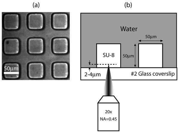
(a) Array of SU-8 polymer pallets. The pallets are cubes with a dimension of 50 μm. (b) Side view of the irradiation geometry.
Both the SU-8 polymer and the living cells are transparent to the 532-nm laser microbeam irradiation wavelength. The optical transparency of both the SU-8 pallets and living cells to 532-nm laser microbeam irradiation suggests that pallet release is likely achieved via a nonlinear optical process. It is well-known that the delivery of pulsed laser radiation at large focusing angles produces high electric field strengths in the focal volume. Such high electric field strengths can result in ionization of the constituent molecules within the focal volume. Optical breakdown occurs when a high volumetric density of ions is produced and results in plasma formation at high temperature and pressure within the focal volume. The subsequent volumetric expansion of the plasma results in the emission of a shock wave and bubble formation that may provide a potential a mechanism for pallet release. Optical breakdown has been studied in liquids where the cooling of the plasma results in cavitation bubble formation, expansion, and collapse.8 However, the precise sequence of events that begin with pulsed laser microbeam irradiation of a SU-8 polymer micropallet and produces pallet detachment is not known and has not been examined mechanistically. Our objectives were to visualize the dynamics of this process and determine the underlying mechanisms of pallet detachment. Moreover, because it is known that the use of shorter laser pulse durations can produce optical breakdown at smaller pulse energies,9 we sought to examine whether pallet release could be accomplished with smaller energies when using shorter pulse durations. Such a mechanistic understanding of the pallet release and its interplay with laser parameters can inform strategies to refine and optimize the release process and minimize cellular damage.
Materials and Methods
Laser Microbeam Irradiation and Time-Resolved Imaging
Figure 2 provides a schematic of the experimental setup used to deliver the pulsed laser microbeam into the sample and perform time-resolved imaging of the pallet release process.10,11 Two lasers are used in this study. The first is a Q-switched, frequency-doubled Nd:YAG laser (INDI-10, Spectra Physics) that delivers 6-ns pulses at λ = 532 nm. The second laser source is a frequency-doubled Nd:YAG laser (SL332, EKSPLA, Vilnius, Lithuania) that provides λ = 532-nm laser pulses with adjustable pulse duration in the range of 180–1100 ps. For this study, we used pulse durations of 1100, 540, and 240 ps supplied by the EKSPLA laser. The pulse-to-pulse energy variation provided by both lasers is ±5%. Both lasers provide output that is linearly polarized and propagate through a half-wave plate to rotate the polarization. A beam splitter divides the beam into two components of low and high energy, respectively. The low-energy beam line is directed through a spatial filter into the epifluorescence port of an inverted microscope (Zeiss Axiovert 100) where it is reflected by a dichroic (532rdc, Chroma Technology Corp., Rockingham, VT) to be focused into the sample by the microscope objective (Zeiss A-Plan 20×, 0.45 NA). The objective focuses the pulse at a distance ∼2 μm above the glass coverslip and in the center of the pallet as shown in Figure 1b.
Figure 2.
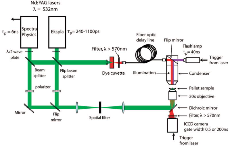
Schematic of laser–microscope setup for pallet release and time-resolved imaging.
The high-energy beam line is focused into a glass cuvette containing a fluorescent dye (LDS 698, Exciton, Dayton, OH) that is excited by the λex = 532 nm laser pulse and emits light at λem = 698 nm. The light emitted by the dye cell is focused into a 600-μm core diameter multimode optical fiber. The output of the optical fiber is directed into the microscope condenser to illuminate the sample for time-resolved imaging. By varying the length of the optical fiber, we can adjust the arrival time of the fluorescent emission relative to the arrival of the low-energy beam line at the sample. The maximum delay time for the fiber-optic delay line is 2000 ns. For longer delay times, we use a flashlamp electronically triggered by the laser. The images are captured by an I-CCD camera (PI-MAX 512, Princeton Instruments, Trenton, NJ) using an exposure time of 1 ns. We use an “emission” filter in the microscope cube to block any stray λem = 532 nm light from reaching the camera.
Pallet Fabrication
We used arrays of 50 × 50 μm square pallets with a height of 50 μm on a number 2 glass coverslip as shown in Figure 1. These pallets were fabricated using SU-8 photoresist that was spin coated on the glass coverslips.6 The coated coverslips are baked on a hot plate to remove the organic solvent and exposed to UV light transmitted through a photomask with the desired pallet features for 30 s. The pallets are finally developed in a SU-8 developer.
Results and Discussion
Threshold Energy for Pallet Release
We examined the characteristics of pallet release as a function of both laser pulse energy (Ep = 1–3 μJ) and pulse duration (tp = 240, 540, and 1100 ps and 6 ns). For a given pulse duration and pulse energy, 10 individual pallets were irradiated with a single laser pulse. We counted the number of pallets that were released at a given energy and pulse duration. Figure 3 provides the probability for pallet release as a function of pulse energy for two of the pulse durations tested.
Figure 3.
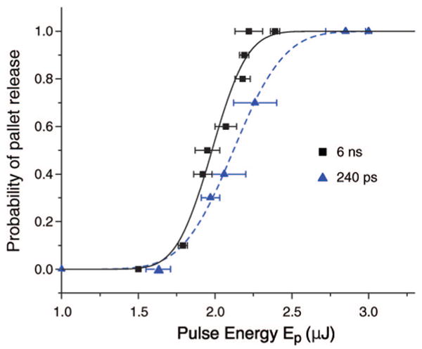
Probability of pallet release as a function of pulse energy for different pulse durations.
The probability of pallet release as a function of pulse energy p(Ep) for each pulse duration was fit to a Gaussian error function of the form p(Ep) = 1/2 {1 + erf[S(Ep − Eth)]}, where S is the “sharpness” of the error function and Eth is the threshold energy for release defined as the pulse energy that produces pallet detachment 50% of the time. Table 1 provides the values of S and Eth for each of the pulse durations tested. The results show that Eth is essentially constant over the range of pulse durations investigated. This suggests that for these pulse durations pallet release is governed by a critical energy dose or incident radiant exposure (J/mm2) rather than a critical laser irradiance (W/mm2).
Table 1. Effect of Pulse Duration on Energy Sharpness S and Threshold E for Pallet Release.
| pulse duration (ps) | S (1/μJ) | Eth, (μJ) |
|---|---|---|
| 6000 | 3.9 ± 0.5 | 1.98 ± 0.02 |
| 1100 | 4.5 ± 0.8 | 2.06 ± 0.02 |
| 540 | 2.9 ± 0.2 | 2.12 ± 0.01 |
| 240 | 2.7 ± 0.2 | 2.12 ± 0.01 |
Time-Resolved Imaging
We visualized the dynamics of pallet release using 540-ps and 6-ns duration laser pulses at laser pulse energies of 1.3Eth, resulting in pulse energies of 2.75 and 2.57 μJ for the 540-ps and 6-ns pulse durations, respectively. Under these conditions, the delivery of a single laser pulse always resulted in pallet release.
Figure 4 shows the dynamics of pallet release achieved by the delivery of a 540-ps duration pulsed laser microbeam at a pulse energy of Ep = 1.3Eth = 2.75 μJ. The pulse arrives at the sample at 0 ns, forming a plasma. A shock wave is created by the plasma expansion and is visible at 4 ns after the arrival of the laser pulse. At 18 ns, the shock wave has already traveled outside the pallet and into the water. The shape of the shock wave is no longer perfectly round due to the square shape of the pallet and the dissimilar shock wave velocities in the SU-8 pallet and the surrounding water. The shock wave can be seen up to time delays of 43 ns after which it passes outside the field of view. At 240 ns, the vapor products of the plasma-mediated polymer ablation process begin to escape from under the pallet. At 738 ns, the ablation vapor products have expanded under the entire pallet but the pallet itself remains in focus, which indicates that the pallet has not yet lifted a significant distance. At 1480 ns, we see a slight defocusing of the pallet edges, indicating that the pallet has moved vertically and is beginning to detach. The products of the polymer ablation continue to expand and attain a maximum volume at ∼5.85 μs when it starts interacting with the surrounding pallets. While the bubble begins to collapse at later times, portions of the bubble seem to attach to the neighboring pallets as seen at the 7.85- and 9.85-μs time points. The vapor bubble has completely collapsed at 11.85 μs, leaving a residual bubble seen in the last frame of Figure 4.
Figure 4.
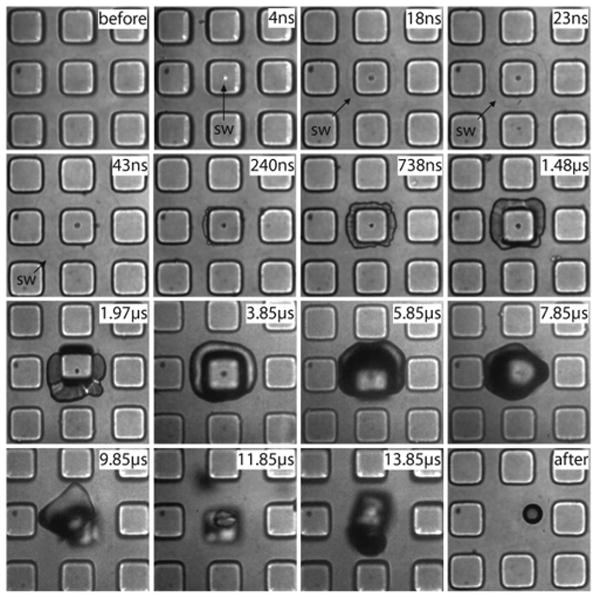
Series of time-resolved photographs showing the pallet release dynamics using a single 540-ps laser pulse. Pallets are 50 μm in size. The formation of a plasma, followed by the emission of a shock wave, emergence of vapor from under the pallet, and pallet release are all visible on the nanosecond to microsecond time scale.
Figure 5 provides the dynamics of pallet release dynamics achieved by the delivery of a 6-ns duration pulsed laser microbeam at a pulse energy of Ep = 1.3Eth = 2.57 μJ. Overall, the dynamics produced by the 6-ns pulse duration is essentially the same as that produced by the 540-ps pulse duration. To examine the process in more detail, we zoom in to visualize only a single pallet and examine more time points between 260 and 1498 ns when the ablation products begin to emerge from under the pallet and the pallet begins to detach. For the 6-ns case, we choose to examine the case where no pallets are adjacent to the pallet being released. The laser pulse arrives at the pallet at 0 ns, creating a plasma that is still visible at 9 ns. For the 6-ns pulse duration, no shock wave is visible in the pallet, but at 28 ns, a shock wave can be seen in the water. At 260 ns, the ablation products begin to emerge from under the pallet. The pallet begins to lift the pallet by 1498 ns. The vapor “bubble” reaches its maximum volume at 3.94 μs and collapses at 7.94 μs.
Figure 5.
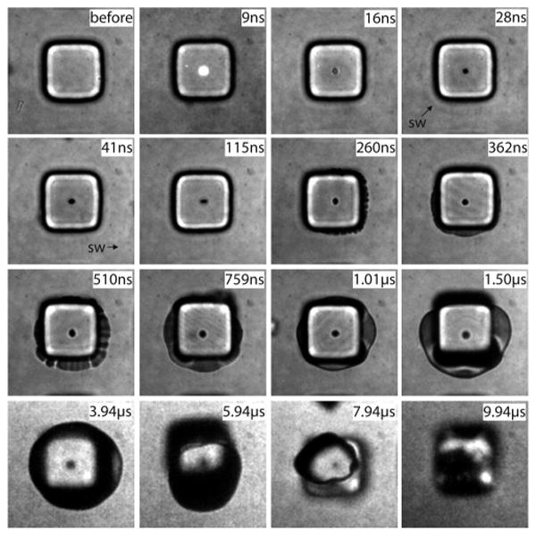
Series of time-resolved photographs showing the pallet release dynamics using a single 6-ns laser pulse. Pallets are 50 μm in size. The formation of a plasma, followed by the emission of a shock wave, emergence of vapor from under the pallet, and pallet release are all visible on the nanosecond to microsecond time scale.
Figures 4 and 5 both show that pallet release is achieved by the expansion of the ablation products from the focal volume where the plasma is formed. While a shock wave is clearly formed in all cases, it appears to have no effect on the pallet release. For both the 540-ps and 6-ns pulse durations, the pallet appears to completely detach from the glass coverslip no later than 1500 ns following the arrival of the laser pulse. One minor difference is the vapor collapse time in the case of pallets detached with the 6-ns laser pulse. This could be explained by the fact that in the 6-ns case there are no neighboring pallets to which the gas bubble can adhere (Figure 4: 7.85 and 9.85 μs) and prolong the bubble collapse.
Discussion
These experimental results provide the data necessary to establish the mechanistic basis for the release of the polymer pallets using pulsed laser microbeam irradiation at λ = 532 nm. Because the SU-8 polymer micropallets are transparent to visible light, the deposition of laser energy within the polymer must be mediated by nonlinear (intensity-dependent) optical processes. Our results demonstrate that pulsed laser microbeam irradiation produces ionization and plasma formation in a process known as optical breakdown.8,12 Optical breakdown achieves pallet release through plasma-mediated ablation of the SU-8 polymer. As shown by the time-resolved photographs, the generation of ablation products at sufficiently high temperature and pressure results in their expansion on the nanosecond to microsecond time scale. This rapid expansion provides the mechanical energy to disrupt the adhesion of the SU-8 polymer pallet and the glass coverslip. The threshold energy for plasma formation in the SU-8 polymer is smaller than the threshold energy for pallet release (Eth) at all the pulse durations investigated. This is confirmed by the observation of plasma luminescence at pulse energies well below those necessary for pallet release regardless of pulse duration. An important implication of this is that pallet release can potentially be achieved at lower laser pulse energies if pallet fabrication protocols can be developed to reduce the adhesion strength between the SU-8 polymer and the glass coverslip.
There are obvious similarities between the use of pulsed laser microbeam irradiation to release polymer micropallets and laser pressure catapulting. In LPC, a highly focused pulsed laser microbeam is used to catapult a sample that has been previously excised using a UV laser beam. In both LPC and micropallet release, a laser-induced plasma is created and results in the emission of a pressure wave during its expansion. However, the LPC process using a focused laser microbeam (beam radius w ∼4 μm) produces significant physical damage as it punctures the specimen.5 This puncture releases the confinement (and pressure) of the ablation products generated between the polymer foil and the glass slide. In this sense, LPC is less “efficient” in converting the mechanical energy of the ablation products into kinetic energy of the catapulted sample.
Defocused laser pulses have also been used in LPC to avoid puncturing the specimen and achieve better confinement of the “ablation” products. The reduced irradiance of the defocused laser does not result in plasma formation. Rather, linear absorption by the polymer foil drives its explosive vaporization. The deposition of the laser microbeam energy in this way preserves the mechanical integrity of the polymer foil. This serves to better confine the ablation products and provides a better transfer of mechanical energy to the specimen, resulting in a higher “catapult” velocity. In studies with live cells, Vogel and co-workers5 reported that for LPC with focused laser pulses (which produces a hole in the periphery of specimen) 98% of the retrieved samples could be recultivated. In contrast, when using a defocused pulsed laser microbeam (w ∼50 μm), the majority of the cells had been sheared off the polymer foil during the catapulting process. As a result, in only 7% of the cases was recultivation possible. Vogel explained this result is due to the shear forces acting on the cells created during the specimen liftoff, with initial velocities of 45–60 m/s, and its interaction with the thin fluid layer above it.
In this study, the pulsed laser microbeam produced by the microscope objective results in a beam radius of w ∼1 μm. Due to the substantial thickness of the SU-8 pallets, the entire sample remains intact. This provides for good confinement of ablation products in a manner similar to the case of LPC using a defocused laser beam. Allbritton and co-workers7 have recultivated single cells obtained via micropallet release and have reported that 97% of the collected pallets retained their single cell. With HeLa cells, 85% of the collected cells grew into colonies by 1 week. For RBL cells, 91% formed colonies by 1 week. This improved success in cell recultivation relative to LPC is likely due to the larger size and mechanical integrity of the SU-8 micropallets.
Conclusions
We have examined the release of optically transparent SU-8 polymer micropallets using pulsed laser microbeam irradiation at λ = 532 nm over a 25-fold range of pulse duration (240 ps–6 ns). These measurements reveal the threshold energy for pallet release to be independent of laser pulse duration. Moreover, time-resolved photography of the pallet release process confirms that laser microbeam-induced plasma formation is a prerequisite for pallet release and provides the means for localized energy deposition at the interface between the SU-8 polymer micropallet and underlying glass coverslip. The plasma formation launches a shock wave and ablates a small portion of the SU-8 micropallet. It is the subsequent expansion of these ablation products, formed at high pressure, over the time scale of hundreds of nanoseconds that accomplishes the pallet release. Thus, pallet release relies on an energy-dependent plasma-mediated ablation process driven by the pulsed laser microbeam irradiation. The deposition of laser energy at the interface of the glass coverslip and SU-8 micropallet is similar to the process of laser pressure catapulting using tightly focused beams. However, the mechanism and dynamics of pallet release are different and do not significantly damage the sample, thereby providing excellent cell viability. The thick SU-8 polymer pallets also provide substrate rigidity and attenuate any possible thermal effects produced by the laser–polymer interaction. Future studies will examine in detail the kinematics of pallet release and the associated fluid stresses and pallet deformation as a function of pallet geometry and pulse energy.
Acknowledgments
We acknowledge support from the National Institutes of Health via the Laser Microbeam and Medical Program P41-RR-01192, R01-EB04436, and R01-EB07612.
References
- 1.Schütze K, Pösl H, Lahr G. Cell Mol Biol. 1998;44(5):735–746. [PubMed] [Google Scholar]
- 2.Schütze K, Lahr G. Nat Biotechnol. 1998;16(8):737–742. doi: 10.1038/nbt0898-737. [DOI] [PubMed] [Google Scholar]
- 3.Mayer A, Stich M, Brocksch D, Schütze K, Lahr G. Methods Enzymol. 2002;356:25–33. doi: 10.1016/s0076-6879(02)56920-2. [DOI] [PubMed] [Google Scholar]
- 4.Stich M, Thalhammer S, Burgemeister R, Friedemann G, Ehnle S, Lüthy C, Schütze K. Pathol Res Pract. 2003;199:405–409. doi: 10.1078/0344-0338-00437. [DOI] [PubMed] [Google Scholar]
- 5.Vogel A, Horneffer V, Lorenz K, Linz N, Hüttmann G, Gebert A. Methods Cell Biol. 2007;82:153–205. doi: 10.1016/S0091-679X(06)82005-4. [DOI] [PubMed] [Google Scholar]
- 6.To'a Salazar G, Wang Y, Young G, Bachman M, Sims CE, Li GP, Allbritton NL. Anal Chem. 2007;79:682–687. doi: 10.1021/ac0615706. [DOI] [PubMed] [Google Scholar]
- 7.Wang Y, Young G, Bachman M, Sims CE, Li GP, Allbritton NL. Anal Chem. 2007;79:2359–2366. doi: 10.1021/ac062180m. [DOI] [PubMed] [Google Scholar]
- 8.Venugopalan V, Guerra A, III, Nahen K, Vogel A. Phys Rev Lett. 2002;88(7):078103. doi: 10.1103/PhysRevLett.88.078103. [DOI] [PubMed] [Google Scholar]
- 9.Quinto-Su PA, Venugopalan V. Methods Cell Biol. 2007;82:113–151. doi: 10.1016/S0091-679X(06)82004-2. [DOI] [PubMed] [Google Scholar]
- 10.Rau KR, Guerra AG, III, Vogel A, Venugopalan V. Appl Phys Lett. 2004;84(15):2940–2942. [Google Scholar]
- 11.Rau KR, Quinto-Su PA, Hellman AN, Venugopalan V. Biophys J. 2006;91(15):317–329. doi: 10.1529/biophysj.105.079921. [DOI] [PMC free article] [PubMed] [Google Scholar]
- 12.Vogel A, Venugopalan V. Chem Rev. 2003;103(2):577–644. doi: 10.1021/cr010379n. [DOI] [PubMed] [Google Scholar]


