Abstract
DNA nanotubes are cylinder-like structures formed from DNA double helical molecules whose helix axes are fused at least twice by crossovers. It is potentially useful to use such tubes as sheaths around rod-like species that arise in biological systems and in nanotechnology. It seems easiest to obtain such sheathing by joining two or more components around an object, rather than attempting to thread the object through a cavity in the tube. We report two examples of tubes containing a specific number of helices that are assembled from half-tube components. These tubes are a six-helix bundle and an eight-helix bundle, constructed respectively from a two bent triple crossover (BTX) molecules and from two 4-helix arched motifs. Both species contain single strands in one molecule that are missing in its mate. The six-helix bundle is formed from two different BTX molecules, whereas the 8-helix species is a closed cyclic dimer of the same molecule. We demonstrate the formation of these species by gel electrophoresis, and we examine their arrangement into long one-dimensional arrays by means of atomic force microscopy.
Keywords: Unusual DNA motifs, DNA tubes, Curved motifs, Specific 1D DNA arrays, Molecular Sheaths
DNA nanotubes have been produced in several laboratories. Many of these nanotubes are effectively combinations of DNA double crossover (DX) molecules, species that contain two DNA double helical domains that are linked to each other by two Holliday-like1 crossover points; thus the two DNA double helices are fused by pairs of strands that cross over from one helix to another.2 The two helix axes are coplanar, so that the unit can be thought of as a box-like unit that may be tailed in sticky ends. DX molecules are known to be quite stiff,3 and have found applications in forming periodic4 and algorithmic5 assemblies, in nanomechanical devices,6 and in a translation system.7 Two different types of DNA nanotubes have been reported: One type is formed from DX molecules tailed with sticky ends that associate with a non-planar angle between them, thereby producing the tube.8,9 This type may be thought of as a two-dimensional array that has closed on itself, deliberately or otherwise, to form a (possibly skewed) cylindrical structure. Such tubes typically have a preferred size, but there is a certain amount of variation around this optimum. A second type of tube is designed to contain an exact number of helices, which is enforced on the molecule by sequence design. The bend angle between DX components is enforced by causing the strand switching between helices to occur at positions that lead to specific structures. For example, for DNA with 10.5 nucleotide pairs/turn, strand switching at separations of 7 or 14 nucleotides leads to 240° or 120° angles, resulting in a six-helix bundle.10,11 A general method for producing low-stress DNA nanotubes with specific numbers of helices and enclosing cavities of designed shapes has been reported recently.12
Regardless of the general interest in designing cavities of particular sizes and shapes, ultimately one would like to be able to use DNA nanotubes to sheathe specific rod-like species that occur either in nanotechnological or in biological systems, such as carbon nanotubes, amyloid fibrils, microtubules or actin filaments. The inherent positional control associated with DNA molecules13–15 makes them extremely attractive as a potential system to organize such species for a variety of purposes. We address this issue here and present molecules that are capable of forming both half-sheaths and full-sheaths.
It seems difficult to thread a potential target species through the cavity at the center of a DNA nanotube. We present a solution to this problem by developing DNA half-tubes designed to cover one side of a rod-like species. We have designed these half-tubes so that they can form full nanotubes, thereby producing the complete cavity, and potentially sheathing its contents. We have done this with two different species, a six-helix bundle (6HB) and an eight-helix bundle (8HB). The six-helix tube is composed of two different bent triple-crossover (BTX) molecules containing a 120° bend between their two DX components; the two BTX molecules join face-to-face to produce the target species. The eight-helix bundle is built from a single arched four-helix component (4HB) that joins with another copy of itself to produce the eight-helix tube.
The structures of the molecules are illustrated in Figure 1; their strand sequences are shown in the supplementary material. A schematic at the far-left of each panel indicates the strand connectivity; the ways that the components fit together are indicated by capital letters and by black arrows. The central portion of the panel shows an idealized cross-section of a structural diagram, and the right part shows a longitudinal image of the structure. Figure 1a shows the structure of the eight-helix bundle. The red arrows indicate the twofold axis relating the two parts of the four-helix arched structure. The way that the two halves combine to make the whole tube is evident in the cross-section view, where the color coding for the helices yields a mirror plane in projection. As described below, the cross-section is somewhat elliptical.
Figure 1.
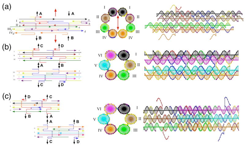
Schematic Drawings of DNA Half-Tube Molecules. At the left of each panel is a line drawing indicating the structure of the half-tube molecules and the ways in which the molecules connect to each other. These are indicated by letters and arrows that connect to the same letters and arrows. Lateral connections are shown as gaps and unpaired strands. In the center of the panels the cross-sections of the complete tubes are shown schematically, and the helices are labeled with Roman numerals. To the right is a view with the helix and tube axes horizontal. (a) The 4HB half-tube molecule. The central portion shows an elliptical cross-section for the 8HB molecule. The dyad axis relating it to itself is drawn vertically as a red double-headed arrow. Only the 4HB molecule is shown at right. (b) The BTX molecules with similar phasing. (c) The BTX molecules phased half a length apart.
As noted above, the design of the six-helix bundle is simple,10,11 but the design of the eight-helix bundle is somewhat more complex. The theoretical diameter of the inner cavity is 3.2 nm when the helices are placed on the edges of regular octagon. We gave higher priority to the two-fold symmetric nature of the 8HB to achieve self-assembly from two 4HB molecules, and correspondingly lower priority to distributing the inner angles evenly. Consequently, we used rather different angles from those of a regular octagon (135°) for each dihedral angle. In helix I, for example, four crossover points from the left in Figure 1a are placed 16 nucleotides (32/21 turn, assuming 10.5 nucleotide pairs/turn), 26 nucleotides (52/21 turn), and 16 nucleotides apart, respectively. As a result, helix I is connected to helix II and another helix I, and the theoretical dihedral angle between DX motifs of I/II and I/I is ca. 171°. Similarly, the theoretical dihedral angles at helix II and III are ca. 154° (15 nucleotides = 10/7 turn) and 120° (14 nucleotides = 4/3 turn), respectively. These angles are calculated on the assumption that all the crossovers are on the straight lines that connect adjacent helix axes. In the actual 8HB molecules, however, some of these crossovers are expected to be off the lines as a consequence of strain on the helices. Figure S3a shows proposed structures of the dimers of arched four-helix bundle capable of binding to itself only at Point A (8HB-A) or at Point B (8HB-B). There is no collision in the theoretical structure of 8HB-A, thus each helix in this motif is expected to be placed just according to the calculated dihedral angles to form a widely open eight-helix bundle. On the other hand, there is an improbable overlapping of helices I due to dihedral angles at helices III and IV that are too small. As a result, 8HB-B may be under strain to resolve this overlap. The closed circular 8HB molecule has both of the above features, and the cross-section of actual 8HB is expected to be somewhat ellipsoidal (Figure 1a). The distance between helix I and helix IV from their mates in the other half is 2.7 nm and the corresponding distance of helix II and helix III is 3.7 nm here. In helix I-III, all of the crossover points are introduced only in one of the two strands in the duplexes to form consecutive crossover-strand series (blue, red, yellow and purple strands in Figure 1a). When the helices are placed at the edges of regular octagon however, the crossover strands in helix IV never come close to each other at the tangent of self-assembly (Figure S3b). Instead, other strands that do not take part in the connection between helix III and IV (the orange strands) meet closely enough for crossover formation. Thus, only in helix IV, we introduced crossovers into both of the strand series, enabling us to close the circle with an inner angle of about 120° about the helix axis.
There are two different formats for the 6-helix bundle; one closes up to form a simple six-helix bundle whose ends are opposite one another. This molecule is shown in Figure 1b. However, the other one, shown in Figure 1c, is an overlapping structure, so that one BTX is phased half the length away from the other, leading to an overlapping structure. In both cases, a half-helix is designed to fit with another half-helix so that a tube can be formed. The differences can be noted in the longitudinal views: Six differently colored helices are evident for the whole length of the molecule in Figure 1b, whereas three colors (helices I, II and III from one BTX molecule) can be seen at the left in Figure 1c, and three different colors (helices IV, V and VI from the other BTX molecule) are visible at the right. We present gel electrophoresis data that demonstrate the robust character and surface properties of the BTX molecules. In addition, we present atomic force microscopy (AFM) data that establish the ability of all of these species to form long tube-like species.
The usual way to establish that a complex DNA motif has been assembled properly is through non-denaturing gels. A stoichiometric mixture of the component strands that produces a single band of mobility similar to that of an identically-sized marker is taken to indicate the formation of the complex, lacking either multimers or breakdown products.16 The gels corresponding to these structures are shown in Figure 2. Figure 2a contains blunt-ended versions of the species shown in Figure 1b, the one designed to produce a discrete six-helix bundle. Lane 2 contains the BTX component formed from helices I, II and III, and lane 3 contains the BTX component formed from helices IV, V and VI. Lane 1 contains the six-helix bundle formed from these two BTX molecules when they cohere. All three lanes indicate a single well-formed product. Figure 2b shows the two BTX molecules that are designed to assemble into the overlapping 6-helix bundle. Both lanes correspond to a robust target molecule, with no multimers and no breakdown products visible. Figure 2c illustrates a subcomponent analysis of the various strands that make up a BTX molecule (Figure S2) lacking overhang strands for combining either laterally (to make a 6HB) or longitudinally (i.e., via sticky ends); this molecule is used for the physical comparison of the BTX molecule with a planar TX molecule.
Figure 2.
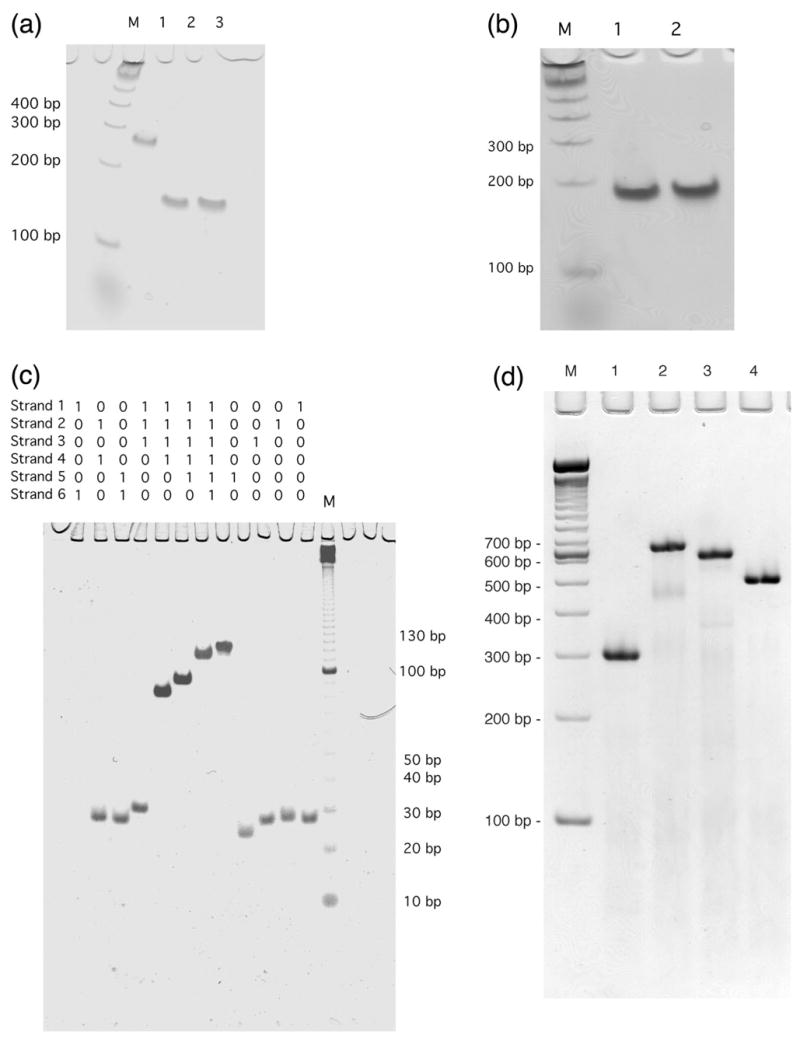
Non-Denaturing Gels Demonstrating Formation of Half-Tube Components. (a) Blunt-ended versions of the BTX molecules phased opposite each other. A marker lane containing 100 nt fragments is labeled M. Lanes 2 and 3 contain the two components and lane 1 shows their cohesion as a clean band. (b) Blunt-ended versions of the molecules that are offset by a half length. Both lanes contain a well-formed single band. (c) The subcomponents of a blunt-ended BTX molecule. The contents of individual lanes are indicated above them, with a ‘1’ indicating the presence of the component. A 10 nt fragment marker lane is at right. (d) Formation of the 8HB from the 4HB molecule. A 100 nt marker lane is labeled ‘M’. Lane 1 contains the individual 4HB molecule without lateral or terminal single strands. Lane 2 contains two molecules joined only at point A (8HB-A), and lane 3 contains two molecules joined only at point B (8HB-B). Both lanes contain various breakdown products. Lane 4 contains the complete 8HB without sticky ends. It is cleanly formed.
Figure 2d illustrates the formation of the eight-helix bundle from the arched four-helix bundle. Blunt molecules are used to avoid aggregation. Lane 1 contains the arched four-helix bundle. Note the clean band visible there, indicating proper target formation. Lane 2 contains the arched four-helix bundle capable of binding to itself only at Point A (See Figure 1a), and lane 3 contains the same material, except that now it is capable of binding to itself only at Point B. In both cases, the lanes contain smears and breakdown products below the main bands. The most prominent of these other features are of greater molecular weight than the 4HB monomer and may indicate species that are dynamically closed (particularly for lane 2) or dissociated from one or both of the linkages. Lane 4 contains the arched four-helix bundle, now capable of binding to itself at both Points A and B. The band is clean, and there is no extraneous material in the lane. This is an important finding, because it indicates that both connection points are necessary to make a well-defined product. The significantly higher mobility than the linear duplex markers of equivalent molecular weight is likely a consequence of the lowered surface area of the circular 8HB motif, as observed with 6HB previously.10 The difference in the mobilities between the two open 8HB species is probably because of irregular inner angles of each edge at the helices. Consistently, open 8HB molecules connected at the self-assembly points with wider inner angles (point A with 171°, lane 2) migrate more slowly than the molecules with a narrower inner angle (point B with 120°, lane 3).
The use of the BTX molecule raises the issue as to its behavior relative to the well-characterized TX molecule whose helix axes are roughly co-planar.17 We have characterized the frictional and thermal properties of the BTX molecule and have compared them to a TX molecule; the TX molecule is the same one described in reference 17. Figure 3a shows the Ferguson plots of the non-overhanging BTX molecule, the TX molecule and a linear duplex DNA molecule, all 42 nucleotide pairs long. The Ferguson plot of gel mobility vs. acrylamide concentration is a means of estimating the friction constant of the molecule, because the slope of the plot is proportional to this quantity.18 The slope of the BTX molecule (.175) is similar to that of the TX molecule (.165) but is still somewhat higher, suggesting that two unequally sized surfaces interact differently with the gel matrix than two roughly equal surfaces. Figure 3b shows the differential melting curve of the same TX and BTX molecules. The BTX molecule melts (Tmax = 64.9 °C) below the TX molecule (Tmax = 68.1 °C). This difference may be a consequence of the electrostatic repulsion likely to result from the closer approach of the outer helices to each other in the BTX molecule. Both molecules exhibit post-melting transitions, and the BTX molecule might also exhibit a pre-melting transition. Figure 3c shows the Ferguson plots of the BTX, the 6HB, the 4HB and the 8HB molecules. The BTX and the 6HB molecules are 63 nucleotides long here, and the 4HB and the 8HB molecules are 84 nucleotides long. One can model the slopes as being proportional surface area, assuming that the interiors of 6HB and 8HB do not interact with the gel matrix, and therefore do not contribute to the friction constant. The plot of the relative surface areas of the six species represented in Figure 3c has a 94.8% correlation with this model (data not shown).
Figure 3.
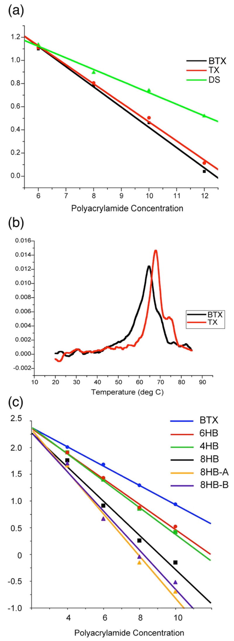
Characterization of BTX and 4HB molecules. (a) Ferguson plots comparing BTX to a conventional planar TX molecule of the same length. A linear duplex molecule (slope = 0.100) is shown for comparison. The BTX molecule is similar, but its slope (0.175) is slightly higher than the planar molecule (0.165). (b) Differential melting plots of the BTX and TX molecules. Note that BTX melts at slightly lower temperatures. (c) Ferguson plots of the species used here. Slopes are BTX (0.180), 6HB (0.235), 4HB (0.251), 8HB (0.319), 8HB-A (0.396), 8HB-B (0.369).
The key goal of this work is to determine the feasibility of building DNA nanotubes from half-tube components. To this end, we have investigated by AFM whether the half-tube species we have made can yield nanotubes. Figure 4a illustrates that long half-tubes readily self-assemble from the 4HB molecule when helices I, II and III contain sticky ends. The left image shows a field 1 μm square that contains many thin thread-like objects on the mica surface. The average length of the tubes is around 450 nm, which corresponds to an assembly of about 13 units of 4HB. The right portion of Figure 4a contains a scan through the image. From this, we find that the average height of the arrays is 2.0 ± 0.3 nm, which is quite close to the theoretical diameter of one DNA double helix, and in good agreement of the expected thickness of 4HB, assuming that all of the four helices adhere to the surface.
Figure 4.
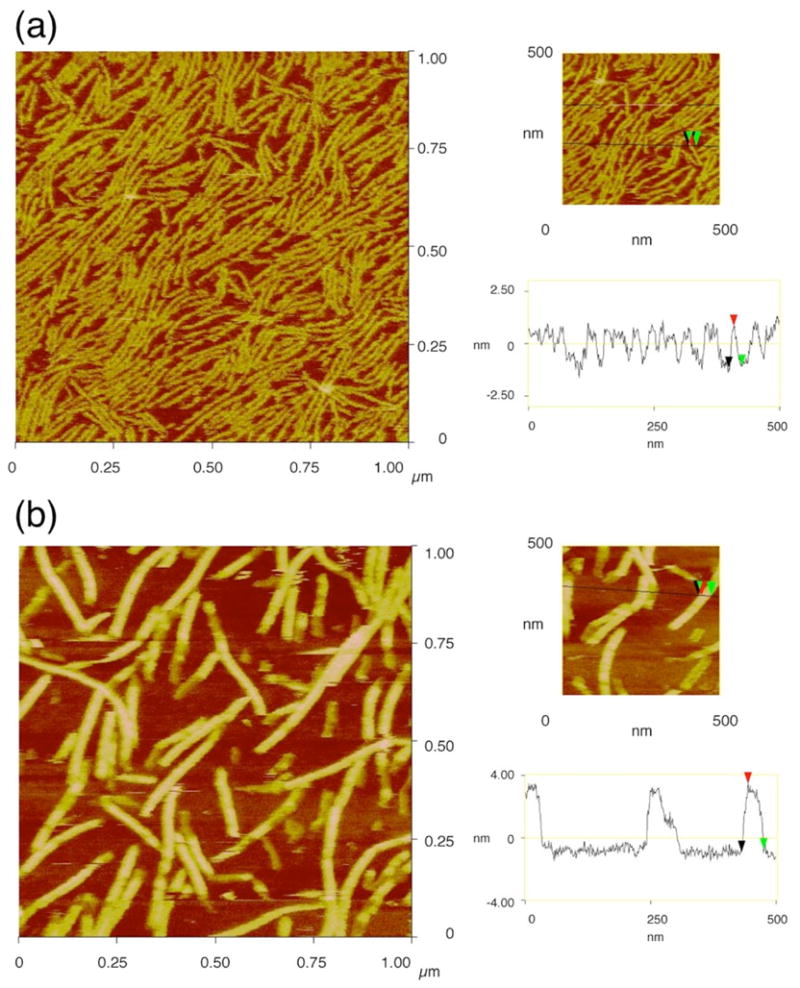
Atomic Force Micrographs of 4HB Half-Tube arrays and 8HB Nanotubes. Both panels contain an image of 1D arrays on the left and a height-analysis on the right. (a) The 4HB half-tube array. The colored arrows on the line indicate the position of the height analysis. (b) The 8HB nanotubes. Note that the tubes are much higher for the 8HB species.
The AFM image of 8HB 1D arrays, on the other hand, shows a strikingly different appearance from that of 4HB (Left of Figure 4b). Each array becomes much thicker, is slightly straighter, and displays a somewhat rounded smooth surface. Most of the 8HB tubes are around 500 nm long, similar to the 4HB arrays, although a few tubes around 1 μm long can be found. The average height of 8HB arrays is 4.5 ± 0.4 nm (right of Figure 4b), which is almost twice as thick as 4HB. This value is very close to that observed with a DX tube previously reported,8 suggesting that the circular 8HB is squashed on mica during AFM measurement. Portions of some of the 8HB tubes appear to be of only half-height (e.g., the right half of the middle sample in the scan), suggesting incomplete assembly or damage during scanning. Linear assembly of both types of open 8HB was also successful, giving ca. 2.0 nm height, similar to 4HB, for both of the arrays (data not shown).
The stoichiometry of the 8HB tubes may appear ambiguous from the image in Figure 4b, where the tip convolution effect leads to wide tubes that could have 2:2 stoichiometry. However, other images show that the width of 8HB tubes is less than double 4HB half-tubes, suggesting that the two sides join 1:1, rather than 2:2 (not shown). There is no concentration dependence of tube thickness in the range of 0.5 – 2.0 μM. The clarity of the molecular weight determination shown in Figure 2d supports this conclusion.
Figure 5 shows the results of assembling the BTX one-dimensional arrays. Figure 5a illustrates the assembly of BTX molecules that form half-tube species that cannot become full 6HB tubes. They readily form many long tubes whose height is about 1.7 ± 0.3 nm. At right is a cross-sectional analysis of 1.8 nm. Figure 5b shows 6HB nanotubes formed from a pair of BTX molecules. Their lengths range from several hundred nm to as long as 8 microns, with an average of about 4–4.5 microns. Their height is 3.5 ± 0.4 nm. At right is a cross-sectional analysis showing a height of 3.4 nm. Thus, these molecules are about twice as thick as the BTX molecules, but not as thick as the 8HB molecules. Figure 5c illustrates 6HB nanotubes formed by the over-lapping motif shown in Figure 1c. Their average height is 3.7 ± 0.3 nm, with an average length of 2–2.5 microns; thus, sticky ends promote somewhat longer molecules. At right is a cross-sectional analysis whose height is 3.9 nm. Note that the parallel nature of the tubes in Figures 4a does not result from single-stranded interactions of the dangling non-complementary single strands, because these molecules do not contain those single strands. The strands are present in Figure 5a, but the parallel nature of those half-tubes is a function of concentration; lowering the concentration from 0.1 μM to 0.01 μM eliminates this effect (data not shown).
Figure 5.
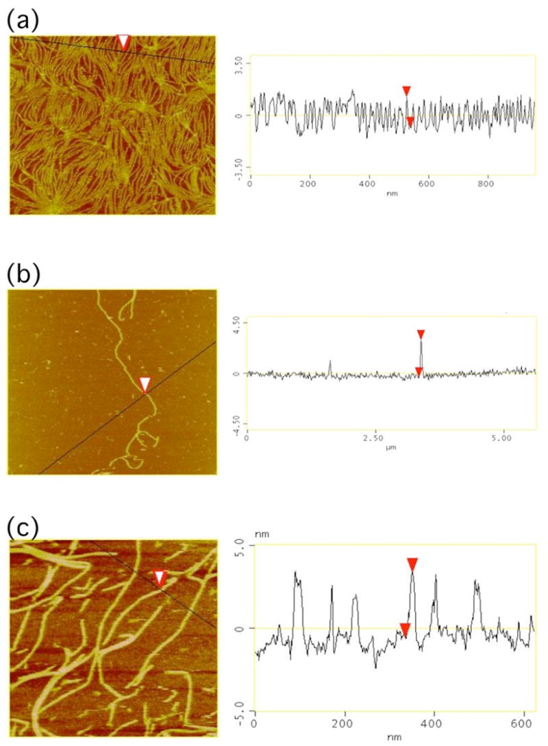
BTX arrays and 6HB Nanotubes. The same conventions apply as in Figure 4, except that the scan line for height analysis is part of the image on the left side of the panel. (a) Long BTX arrays are shown; the image is 950 nanometers square. (b) A 6HB nanotube formed from a pair of BTX molecules phased opposite each other; the image is 5 microns square. (c) 6HB nanotubes formed from the overlapping motif, with BTX molecules phased half a length apart; the image is 820 nanometers square.
We have demonstrated that it is possible to make specific DNA nanotubes from components corresponding to half their circumference. We have done this in three ways: [1] We have built specific 6HB molecules by combining two different BTX molecules to produce a 6HB whose ends are phased together. These molecules have been combined by sticky-ended cohesion at their centers and tips to yield nanotubes. [2] We have built 6HB nanotubes by producing two different BTX molecules that are phased half a length from each other. These molecules also combine to produce 6HB nanotubes that are linked by cohesion only at their centers without sticky ends on their tips. [3] We have built 8HB molecules from an arched 4HB molecule that is capable of combining with itself to product the 8HB species. These 8HB species are also linked together to produce 8HB nanotubes. It is worth pointing out that the lateral interactions used to produce 6HB and 8HB molecules represent a new type of intermolecular cohesion, distinct from sticky ends, for joining DNA motifs.
An open question arises from these studies. If it is possible to make a specific nanotube from half-bundles, is it possible to make a specific nanotube from smaller fractions of the circumference? It is not very hard to make a nanotube with the small diameters described here from specific strands. However, larger nanotubes may require many more helices. For example, a DNA nanotube with an inner diameter of about 10 nm will require around 20 helices. Is it necessary to build such a specific nanotube with two 10-helix half tubes, or could four 5-helix tubes be as effective? A related issue is the distortion of the individual components when symmetry is imposed perpendicular to the tube axis, rather than parallel to it. The imposition of twofold symmetry on the 4HB molecule here has led to a significant distortion from an ideal 4-helix arch with similar dihedral angles between DX portions.
We believe the value of this work is that we have demonstrated that larger tubes can be built from subcomponents that correspond to only a portion of the circumference. We expect this capability to enable the sheathing of other species of rod-like systems. The outstanding control that DNA lends to the organization of matter (e.g. ref 14) will facilitate our ability to organize guest species in the future. It is likely that chemical modification of the inner surfaces of DNA nanotubes will be necessary to sheath species whose chemical properties are significantly different from those of DNA.
Supplementary Material
The experimental methods, the sequences and estimated molecular structures of open components. This material is available free of charge via the Internet at http://pubs.acs.org/.
Acknowledgments
We thank Dr. William B. Sherman for advice on the design of the 4HB and 8HB molecules. This research has been supported by grants GM-29554 from NIGMS, grants DMI- 0210844, EIA-0086015, CCF-0432009, CCF-0523290 and CTS-0548774, CTS-0608889 from the NSF, 48681-EL from ARO, DE-FG02–06ER64281 from DOE (Subcontract from the Research Foundation of SUNY), and a grant from the W.M. Keck Foundation, to N.C.S. AK has been supported by a JSPS Research Fellowship for Young Scientists.
Contributor Information
Akinori Kuzuya, Email: akinori.kuzuya@nyu.edu.
Risheng Wang, Email: rsw224@nyu.edu.
Ruojie Sha, Email: rs17@nyu.edu.
Nadrian C. Seeman, Email: ned.seeman@nyu.edu.
References
- 1.Holliday R. Genet Res. 1964;5:282–304. [Google Scholar]
- 2.Fu TJ, Seeman NC. Biochem. 1993;32:3211–3220. doi: 10.1021/bi00064a003. [DOI] [PubMed] [Google Scholar]
- 3.Sa-Ardyen P, Vologodskii AV, Seeman NC. Biophys J. 2003;84:3829–3837. doi: 10.1016/S0006-3495(03)75110-8. [DOI] [PMC free article] [PubMed] [Google Scholar]
- 4.Winfree E, Liu F, Wenzler LA, Seeman NC. Nature. 1998;394:539–544. doi: 10.1038/28998. [DOI] [PubMed] [Google Scholar]
- 5.Rothemund PWK, Papadakis N, Winfree E. PLOS Biology. 2004;2:2041–2053. doi: 10.1371/journal.pbio.0020424. [DOI] [PMC free article] [PubMed] [Google Scholar]
- 6.Mao C, Sun W, Shen Z, Seeman NC. Nature. 1999;397:144–146. doi: 10.1038/16437. [DOI] [PubMed] [Google Scholar]
- 7.Liao S, Seeman NC. Science. 2004;306:2072–2074. doi: 10.1126/science.1104299. [DOI] [PMC free article] [PubMed] [Google Scholar]
- 8.Rothemund PWK, Ekani-Nkodo A, Papadakis N, Kumar A, Fygenson DK, Winfree E. J Am Chem Soc. 2004;126:16344–16352. doi: 10.1021/ja044319l. [DOI] [PubMed] [Google Scholar]
- 9.Mitchell JC, Harris JR, Malo J, Bath J, Turberfield AJ. J Am Chem Soc. 2004;126:16342–16343. doi: 10.1021/ja043890h. [DOI] [PubMed] [Google Scholar]
- 10.Mathieu F, Liao S, Mao C, Kopatsch J, Wang T, Seeman NC. NanoLett. 2005;5:661–665. doi: 10.1021/nl050084f. [DOI] [PMC free article] [PubMed] [Google Scholar]
- 11.Constantinou PE, Wang T, Kopatsch J, Israel LB, Zhang X, Ding B, Sherman WB, Wang X, Zheng J, Sha R, Seeman NC. Org Biomol Chem. 2006;4:3414–3419. doi: 10.1039/b605212f. [DOI] [PMC free article] [PubMed] [Google Scholar]
- 12.Sherman WB, Seeman NC. Biophys J. 2006;90:4546–4557. doi: 10.1529/biophysj.105.080390. [DOI] [PMC free article] [PubMed] [Google Scholar]
- 13.Garibotti AV, Knudsen SM, Ellington AD, Seeman NC. NanoLett. 2006;6:1505–1507. doi: 10.1021/nl0609955. [DOI] [PMC free article] [PubMed] [Google Scholar]
- 14.Zheng J, Constantinou PE, Micheel C, Alivisatos AP, Kiehl RA, Seeman NC. NanoLett. 2006;6:1502–1504. doi: 10.1021/nl060994c. [DOI] [PMC free article] [PubMed] [Google Scholar]
- 15.Ding B, Seeman NC. Science. 2006;314:1583–1585. doi: 10.1126/science.1131372. [DOI] [PMC free article] [PubMed] [Google Scholar]
- 16.Seeman NC. Curr Protocols Nucl Acid Chem. Unit 12.1. John Wiley & Sons; New York: 2002. [Google Scholar]
- 17.LaBean T, Yan H, Kopatsch J, Liu F, Winfree E, Reif JH, Seeman NC. J Am Chem Soc. 2000;122:1848–1860. [Google Scholar]
- 18.Rodbard D, Chrambach A. Anal Biochem. 1971;40:95–134. doi: 10.1016/0003-2697(71)90086-8. [DOI] [PubMed] [Google Scholar]
Associated Data
This section collects any data citations, data availability statements, or supplementary materials included in this article.
Supplementary Materials
The experimental methods, the sequences and estimated molecular structures of open components. This material is available free of charge via the Internet at http://pubs.acs.org/.


