
Figure 7.
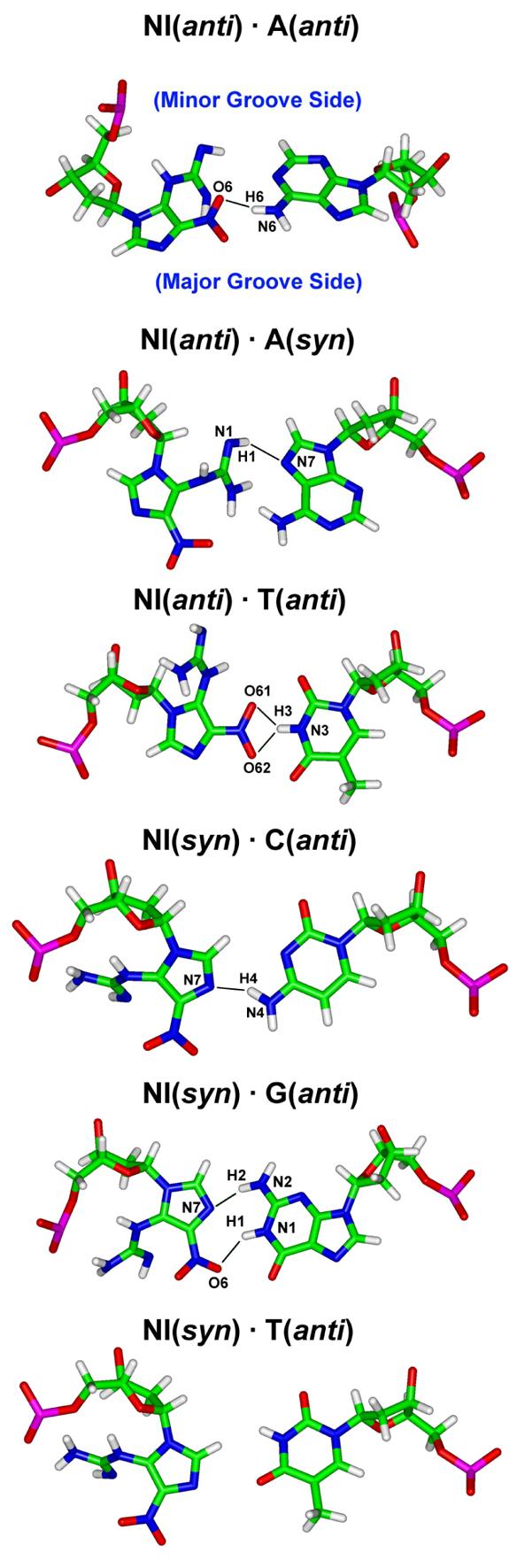
Hydrogen bonds (black lines) between NI and partner base. The low energy structures of Table 3 are shown. The base pairs are obtained from the trajectory average structures of the selected simulation window. Hydrogen bonds shown have occupancy greater than 50%. Major and minor groove sides for all structures are designated in the first pair.