Abstract
Interactions of pulverized crystalline silica with biological systems, including the lungs, cause cell damage, inflammation, and apoptosis. To allow computational atomistic modeling of these pathogenic processes, including interactions between silica surfaces and biological molecules, new parameters for quartz, compatible with the CHARMM empirical force field were developed. Parameters were optimized to reproduce the experimental geometry of α-quartz, ab initio vibrational spectra and interactions between model compounds and water. The newly developed force field was used to study interactions of water with two singular surfaces of α-quartz, (011) and (100). Properties monitored and analyzed include the variation of the density of water molecules in the plane perpendicular to the surface, disruption of the water H-bond network upon adsorption, and space-time correlations of water oxygen atoms in terms of Van Hove self correlation functions. The Vibrational Density of States (VDOS) spectra of water in confined compartments were also computed and compared with experimental neutron-scattering results. Both the attenuation and shifting to higher frequencies of the hindered translational peaks upon confinement are clearly reproduced by the model. However, an upshift of librational peaks under the conditions of model confinement still remains underrepresented at the current empirical level.
Keywords: Quartz, Silica, Liquid Water, Neutron-Scattering, Van Hove Self-Correlation Function, Force Field, CHARMM, Vibrational Density of States, VDOS
1. Introduction
Silica or silicon dioxide is a ubiquitous compound commonly found in the form of α-quartz. Being a major constituent of rocks, silica represents a significant part of industrial dust in mining, construction and manufacturing processes. Workers with long term exposures to respirable quartz-contaminated dusts are at risk of developing pulmonary fibrosis and coal workers’ pneumoconiosis, and eventually lung cancer.1 Although already Pliny and Hippocrates were aware of silica-dependent pulmonary inflammation (silicosis), the aetiology of biological toxicity and pathogenicity of silica polymorphs remains controversial. Over 50 theories have been proposed to explain the phenomenon of silicosis.2 The widely accepted ones attribute pathogenicity of crystalline silica to the presence of silanol groups at silica surface.3 Blocking silanol groups with chemical agents reduces or eliminates silica toxicity. These protective agents include natural surfactants,4 polyvinylpyridine-N-oxide,5 aluminum compounds,6 divalent cations,7 trimethylchlorosilane8 and high molecular weight organosilanes.9 Silanol hydroxy groups can form strong hydrogen-bond complexes with biological molecules, for instance organic phosphate groups.10 Silanol bonding and physisorption to the phosphate head-groups of cell membranes11 may alter membrane properties and consequently cause depolarization of membranes, increased levels of reactive oxygen species,9 and ultimately cell damage, pulmonary inflammation, and apoptosis12,13. The chronic inflammatory injury may be caused by intermittent reactivation of silanol groups in vivo, for example by phospholipases.14 Nonetheless, the described aetiology of silanol group toxicity, although plausible, remains hypothetic unless clear connections between macroscopic and microscopic events of pathogenesis are made.
The microscopic part of silica pathogenicity is especially poorly understood. It is known that silanol groups on only crystalline silica are noxious. Amorphous silica and silica in phyllosilicates (e.g. kaolinite) cause virtually no adverse long-term health effects.4 The situation is confounded by variability, error bars, and interpretation of experimental results, which include biological variability, variations in cytotoxicity of quartz dust from different sources,15 multiple crystalline silica polymorphs,16 and other factors. In another study some of us have found that silica toxicity is associated with the surface density of geminal, but not single, silanol groups.16a The chosen surfaces represent typical examples of silica surfaces that are covered with either exclusively single, like on (011) and (100)S forms of quartz, or geminal, like on (100)G, silanol groups. The developed force field extension is designed for the groups of both types. The pure-single and pure-geminal surfaces are used for validation. Physical chemical characterization of silica surface and its interactions with biological targets may shed light on molecular aetiology of silanol pathogenicity, although extrapolations of measured macroscopic averages from the ensemble of dust particles to the microscopic level could be ambiguous.
Quantitative physical-chemical characterization of silica surface represents a major challenge to experimental science. For instance Nuclear Magnetic Resonance (NMR) suffers because of low concentration of surface silanol groups (2D) comparing to the bulk (3D) and disparities between liquid and solid-state NMR (e.g. the latter technique involves sample spinning at the magic-angle).17,18 X-ray reflectivity also has significant limitations.19 Since all crystalline silica polymorphs are known to break along conchoidal fracture, even creation of a sufficiently large fresh singular surface represents a formidable challenge. In this situation computational methods possess an unsurpassable advantage, if they are tuned correctly. The present paper addresses this topic. In the absence of reliable experimental data about interactions of biological molecules (such as proteins and lipids, including dipalmitoyl phosphatidylcholine) with silica surface, we chose to parameterize and validate the force field using high-resolution data on silica-water interactions. Our past experience suggests that appropriate modeling of interactions with water molecules is a crucial step in the derivation of self-consistent molecular mechanical force field.
Computational experiments offer a complementary approach, in which a systematic characterization of silica surfaces can be carried out under carefully controlled conditions. In silico the silica surface is represented by an infinite slab with which water, organic molecules and biopolymers can interact via an interatomic potential under constant volume or pressure conditions.* To insure the reliability of such methods, it is essential that the interatomic potentials that describe interactions of biological molecules in the liquid phase and potentials representing silica in the solid state are compatible. In the present work we describe extensions to the CHARMM suite, which allow modelling of mixed crystalline silica / liquid phase systems. The extensions include new force field parameters for silica compounds and coding tools for modelling periodic solid state crystals. During the past 25 years there have been many attempts to develop silicate force fields.20-24 A variety of techniques have been used in the parameterizations, ranging from ab initio calculations of small clusters to fitting to experimental data such as structures, vibrational spectra, elastic constants or melting points. A comparison of previous force fields has been recently reported by Herzbach and co-workers.25
2. Methods and experimental details
Empirical force field calculations were performed with the programs CHARMM26,27 and Tinker.21 Tinker was used for the initial constant pressure simulations since constant pressure algorithms of CHARMM do not allow for internal terms between the primitive and image cells. CHARMM (Chemistry at HARvard Molecular Mechanics) was used for all force field optimization calculations and for all production simulations. Quantum mechanical (QM) computations were performed with the Gaussian 98 package.28 Density Functional Theory with the B3LYP functional at the 6-31G* level was used for the geometry optimizations and vibrational analysis.29 The HF/6-31G* level of the theory was used to calculate minimum interaction energies and geometries between model compounds and water.29
Infinite quartz surfaces were modeled as quartz slabs and each was cut from a primitive unit cell of bulk α-quartz along the desired directions using the Cerius2 software (Accelrys, Inc., San Diego, CA). Two surfaces were studied, quartz (011) and quartz (100), and will be referred to by the respective Miller index hereafter. The thickness of each slab is approximately 15 Å to isolate the two faces from mutual interactions while maintaining interactions between the surface groups and the bulk phase. The initial structures were obtained from the primitive unit cells representing the slabs by replicating them a sufficient number of times to build a two-dimensional unit cell with a surface area of approximately 30 × 30 Å2. The generation of cross-boundary patches, involving creation of bonds, angles and dihedrals lists, was assisted by a standalone utility program developed specifically for this purpose. It is included in the Supplementary Material, together with an example of the input files that are required to use the new CHARMM parameters. The image facility of CHARMM was then used to replicate the primary cell, thus creating the periodic boundary conditions. Bond, angle and torsion angles in the crystal spanning the boundaries of the unit cell were accounted for explicitly using the PATCH command. Different surface saturation schemes were considered. In the studies of the dynamical properties of adsorbed water one surface was saturated with hydroxyl groups, which resulted in full coverage by Si-OH groups (Figure 1, silanols), and the other face was hydrogenated, being covered by Si-H groups (Figure 1, silanes). These systems allow the study of the interactions between water and hydrophilic or hydrophobic hydrogenated (note: most commonly occurring natural hydrophobic silica surfaces are covered with siloxane Si-O-Si bridges) quartz surfaces. The simulation unit cell in these cases consisted of a 30 Å thick layer of water placed between the quartz surfaces and is shown as Model 1 on the left panel of Figure 2. For the confinement studies both sides of the quartz slabs were terminated with Si-OH groups, since the separation of the two surfaces in the direction of surface normal was insufficient to avoid inter-image interactions and silanols are the most natural groups on the quartz surfaces.30 A schematic representation of these systems is shown as Model 2 on the right panel of Figure 2.
Figure 1.
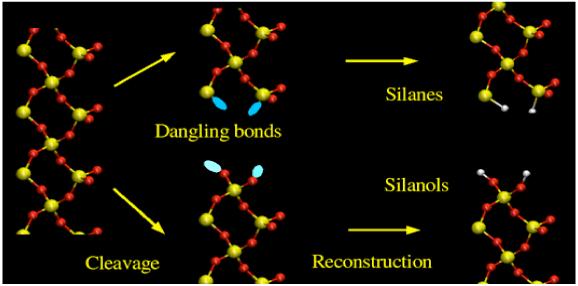
Cleavage of bulk quartz and idealized (100) surface formation and reconstruction. The hydrophilic side is covered by silanols (Si-OH) and on the hydrophobic side silicon atoms are saturated with hydrogens (Si-H).
Figure 2.
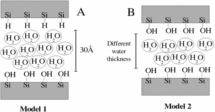
Models of the systems used in this work. Model 1 was used for the adsorption studies and Model 2 was used in the simulation of the VDOS spectra. Different thicknesses of the water slab were employed.
All molecular dynamics (MD) simulations were performed using periodic boundary conditions. The length of the simulation cells was determined by performing constant pressure MD simulations with the algorithm developed by Berendsen31. A partially flexible cell was employed with the magnitude of the c vector (corresponding to the z-axis in Cartesian coordinates) being adjusted to maintain the pressure at 1 atm. The surface normal was orientated collinear to the c dimension while the a and b vectors were kept fixed. Long range electrostatic interactions in CHARMM were truncated due to the Ewald summation algorithm being incompatible with the covalent linkages between the primary and image atoms. Non-bonded interactions were computed on an atom-atom pair basis using a constant dielectric of 1.32 Force shift and force switch smoothing of the electrostatic and Lennard—Jones (LJ) interactions,32respectively, was performed with the force switch initiated at 10 Å, non-bonded interactions truncated at 12 Å and non-bond pair lists were maintained heuristically to 14 Å. Hydrogen atoms were constrained at their equilibrium bond length distances using the SHAKE algorithm.33 The equations of motion were integrated using the Verlet algorithm34 with a 2 fs time step. The temperature was maintained at 303K using the Nosé-Hoover chain thermostat.35 Trajectories were saved every 5 ps for subsequent analysis. The total simulation length was 6ns although only the last 5ns were used in the analysis, the first nanosecond being considered as equilibration.
3. CHARMM parameter development. Methodology and results
The CHARMM empirical force field is well described in the literature.26,27 The total energy of a system is calculated by summing different terms given in Equation 1. It is composed of a bonding part that includes bond, angle, torsion, Urey-Bradley and improper torsion terms and a non-bonding part comprising electrostatic and LJ terms
| (1) |
Equation 1 is a function of several variables: the bond length, b, the distance, S, between atoms separated by two covalent bonds (1,3 distance), the valence angle, θ, the dihedral or torsion angle, χ, the improper angle, φ, and the distance between atoms i and j, rij. The ability of the CHARMM force field to describe different systems relies on the choice of parameters in Equation 1. These include the bond force constant and equilibrium distance, Kb and b0, respectively, the Urey-Bradley force constant and equilibrium distance, KUB and S0, respectively, the valence angle force constant and equilibrium angle, Kθ, and θ0, respectively, the dihedral force constant, multiplicity and phase angle, Kχ, n and δ, respectively, and the improper force constant and equilibrium improper angle, Kimp and ϕ0, respectively. These terms are referred to as the bonding parameters. Also optimized were the non-bonding or interaction parameters between atoms i and j including the partial atomic charges, qi, and the LJ well-depth, εij, and minimum interaction radius, Rmin,ij, used to treat the van der Waals (VDW) interactions. Typically, εi and Rmin,i are obtained for individual atom types and then combined to yield εij and Rmin,ij for the interacting atoms via combining rules. In CHARMM εij values are obtained via the geometric mean εij = sqrt(εi * εj) and Rmin, ij via the arithmetic mean, Rmin, ij = (Rmin,i + Rmin,j)/2. The dielectric constant, e, is set to one in all calculations, corresponding to the permittivity of vacuum.
Force field development in CHARMM follows a strict set of steps to ensure consistency and quality of the determined parameters. Consistency is the ability of a parameter set developed for a class of compounds to be used in conjunction with parameter set(s) developed for different classes of compounds. An example is the present work where the newly developed parameters for quartz can be used with existing CHARMM parameter sets.36 The quality of a determined force field is judged by its ability to reproduce a variety of selected experimental or calculated properties. These are often referred as target data. The methodology is illustrated in the flowchart of Figure 1 of reference30 and will not be described here. It relies on the reproduction of the target data for small molecules also referred to as model compounds. These small molecules are simplified models of the real systems and are designed to carry their most significant characteristics. For example, if the real system has an exposed acidic group relevant for interactions with the environment, the model compound will include the same acidic group. In the CHARMM methodology bonding parameters are optimized to reproduce geometries, vibrational spectra and conformational energies for the model compounds. Partial atomic charges and LJ parameters are optimized by reproducing minimum interaction energies and geometries between a water molecule and the chemical groups of the small molecule in a variety of orientations along with various experimental condensed phase properties when available. The target interaction energies and geometries with water are calculated at the ab initio HF/6-31G* level of the theory. Again, this QM level is used to maintain compatibility with the remainder of the force field. 20
The first step to determine high quality force field parameters is the selection of adequate model compounds. In the present case assumptions had to be made on the nature of the real system itself. Silica surfaces are intrinsically complicated and the simplified model consists of slabs terminated by silanol groups (hydrophilic surfaces). We also consider hydrophobic surfaces resulting from the saturation of silicon dangling bonds with hydrogen atoms resulting in silane (Si-H) fragments (see Figure 1). Model compounds were designed to include functional groups present in the bulk and on the surface of silica, including SiO2 units and Si-OH or Si-H groups, respectively. Depending on the surface, surface silanols can be single or double (geminal). A simplification was introduced and consists in considering only double surface groups in the parameter development process. Accordingly, simple model compounds to include these components were designed and are shown in Figure 3. Compound A contains Si-O-Si and O-Si-H fragments and was used as a target to optimize Si-O and Si-H bond terms, Si-O-Si and O-Si-H angles and Si-O-Si-O and Si-O-Si-H torsions. Compound B was used to optimize Si-O(H) and O-H bond terms, Si-O-H angle terms and O-Si-O-H dihedral terms.
Figure 3.

Model compounds used for the optimization of internal parameters. Model A (left) was used to optimize Si-O and Si-H bond terms, Si-O-Si and O-Si-H angles and Si-O-Si-O and Si-O-Si-H torsions. Model B (right) was used to optimize Si-O(H) and O-H bonds, Si-O-H angles and O-Si-O-H dihedrals.
Bond, angle and dihedral force constants associated with the model compounds were optimized by reproducing QM vibrational spectra. The QM calculations were performed at the B3LYP/6-31G* level and the frequencies were scaled by 0.96.31 Presented in Table S4 of the Supplementary Material are the QM and CHARMM vibrational spectra, including the assignment of the modes computed at the QM level. In Table 1 minimized bond lengths, valence angles and torsions determined at the B3LYP/6-31G* level for the two model compounds are compared with the equivalent CHARMM results. There is a good agreement on the bond distances, thus validating the choice of the model compounds. The differences are smaller for compound B (see Figure 3A) because its target data was reproduced more accurately since it gives a more realistic approximation to the hydroxylated quartz surfaces. The agreement on the angles is poorer. However, due to the fact that the force constants associated with these coordinates are small this is not a significant problem and the angles and torsions can easily distort in the crystal to reproduce their experimental values. LJ parameters and partial atomic charges were optimized by reproducing the interactions between water and the model compounds. In addition to the optimization of the internal parameters, compound B (Figure 3B) was also used in the optimization of the non-bonding parameters, with the interactions with water being depicted in Figure 4.
Table 1.
Comparison of QM and CHARMM geometries of compounds A and B (Figure 3)
| Compound A | Compound B | |||
|---|---|---|---|---|
| QM | CHARMM | QM | CHARMM | |
| Bonds (Å) | ||||
| Si-O(Si) | 1.636 1.634 |
1.635 1.649 |
1.633 1.639 |
1.636 1.648 |
| Si-O(H) | na | na | 1.650 1.645 |
1.629 1.640 |
| Angles (°) | ||||
| Si-O-Si | 162.2 179.5 |
138.1 129.3 |
142.6 140.1 |
129.3 138.1 |
| O-Si-O | 111.4 | 108.6 | 107.2 | 108.6 |
| O(H)-Si-O | na | na | 111.1 111.1 109.2 107.3 |
107.5 114.2 114.4 106.8 |
| O(H)-Si-O(H) | na | na | 106.9 | 109.4 |
| Si-O(H)-H | na | na | 115.3 114.8 |
127.7 137.8 |
| H-Si-H | 111.1 | 109.4 | na | na |
na: not applicable to this compound
Figure 4.
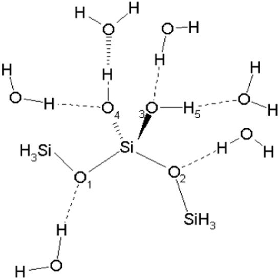
Model compound-water interactions used for the optimization of nonbonded parameters. Note that monohydrates were studied although all waters are presented simultaneously in the Figure. Interaction energies and distances are shown in Table S5 of the Supplementary Material.
Testing of the newly developed parameters was also performed by optimizing the geometry of the two quartz slabs, (011) and (100), as in the MD simulations in the presence of water. Topology and parameter files for both surfaces are provided in the Supplementary Material. The agreement between the optimized structures and crystalline quartz is again good. Empirical computations Si-O bond distances are between 1.622 and 1.686 Å and compare with the experimental values of 1.600 and 1.615 Å. There are no significant differences between results from (011) and (100) surfaces. Calculated Si-O-Si angles range between 134.6 and 140.6°and the experimental value is 143.0°. The O-Si-O angles have a larger variation, between 98.7 and 114.4°, the experimental ones being 109.5 and 112.9°.
4 Results and discussion
4.1 Parameter testing and validation. Dynamics of water in confinement
In recent years a considerable amount of interest has been dedicated to the investigation of dynamic properties of liquid water under spatially restricted conditions. When water molecules are adjacent to surfaces or filling cavities their properties are often altered relative to the bulk state. The effect may result purely from restrictions on the diffusion of water, may be caused by physical-chemical interactions between the solid and water molecules, for example H-bond interactions, or by a combination of both. This phenomenon is referred in the literature as water in confinement.
Experimental research in this area has been inspired by recent progress in physical methods, such as quasi-elastic or inelastic neutron scattering.37 An overview of this topic has been published recently.38 In particular, the structure of water confined in various types of porous silica has been reported.39-44 One such method, the experimental “Vibrational Density of States” (VDOS) spectra of confined water, is directly relevant for the present topic of discussion in which the experimental and computed results will be compared. VDOS is easily accessible from MD trajectories as the Fourier transform of the velocity auto-correlation function. In practice, one takes short MD simulations, for example, 1 ps long, and saves the trajectories every 1 fs. The computed VDOS spectrum is the Fourier transform of the velocity auto-correlation function. In the present work VDOS spectra from three experimental studies are compared with the computed ones. Funel and co-workers37,45 studied VDOS spectra and single-particle dynamics of water molecules confined in nanopores of Vycor glass and Crupi and co-workers41 analyzed the behavior of water in bulk and when it is confined in a sol-gel porous glass.
VDOS of confined water exhibits some specific features. First, the peak associated with the hindered translational modes, identifiable as intermolecular bending motions, occurring between 6-8 meV, is significantly attenuated, indicating a reduction of this degree of freedom upon confinement.32,41 It is also shifted to higher frequencies.37 Second, there is an enhancement of the librational modes having the lowest moment of inertia (centered at about ∼91 meV) which results in the shifting of the librational peak (∼70 meV) to higher energies, indicating hindrance of the librational motions because of the presence of the surface.41 Computed VDOS spectra of confined water are presented in Figure 5. Two systems were generated by confining 252 and 474 water molecules between a quartz slab and its image. In order to avoid hydrophobic effects both faces of the quartz slabs were terminated with silanol groups as depicted in Model 2 of Figure 2. Three main features of the simulated confined water were observed. For all systems, confined and bulk water alike, the computed and experimental spectra have a similar shape (see Figure 5). The hindered translational peak at ∼6 meV and the broad librational peak at ∼55 meV are clearly defined and follow the experimental curve.37 The attenuation and up-shifting of the hindered translational peak is evident as the depth of the water slab decreases (Figure 6). These plots are shifted along the y-axis in order to have common minima at ∼13 meV. The librational peak at approximately 55 meV is typical for both the confined and bulk simulated states but does not change with confinement. This deviates from the experimental findings, which suggest an up-shifting when water is confined.37,46 The librational peak results from the librational (rocking) modes around the three possible symmetry axes of water.
Figure 5.
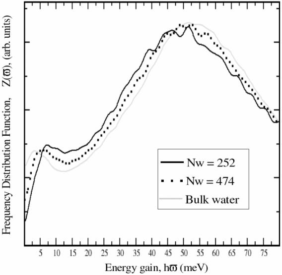
VDOS of water confined between quartz slabs. VDOS of bulk water is shown in grey.
Figure 6.
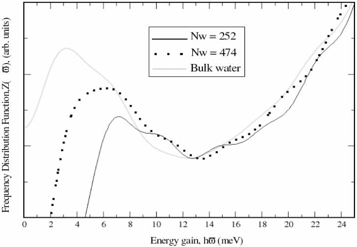
Detail of the attenuation of the translational peak upon confinement.
Water molecules inside cavities are able to interact with other waters and with the surface atoms for example through H-bonds, and have their movements restricted in all directions but one, corresponding to the opening of the pore. The model used in this study varies from experimental conditions since restriction on the movement of waters only occurs in the direction perpendicular to the surface due to the proximity of the quartz surfaces. Experimentally water is constrained in all directions except one, corresponding to the opening of the pore. However, the results in Figures 5 and 6 provide support that the newly derived parameters are compatible with the existing CHARMM parameters (see Figure 5 and Figure 6). It would be very interesting to extend the present work and perform the calculation with a more realistic cavity structure.
4.2 Layering effects of the water slabs
Quartz surfaces are expected to disrupt the order of the water molecules in the direction of normal to the surface due to surface groups introducing new surface-water interactions, for example, new silanol-water H-bonds. The distortion of H-bonding typical to bulk waters has been suggested by studies of water confined in Vycor glass47,48 and in contact with other surfaces.49,50 In order to gain insight into the microscopic structure of water adsorbed on quartz surfaces, an in-depth analysis of the present MD trajectories was performed. Layering effects on water introduced by the surfaces were analyzed for both the (011) and (100) quartz surfaces under the conditions depicted in Model 1 (Figure 2A). Quartz is covered by silanols on one face and silane groups on the other. The silanol covered surface is purely hydrophilic in contrast with the all silane face, which is hydrophobic. The computed density profiles are shown in Figure 7. The light shaded peaks mark positions of the quartz surface hydrogen atoms, irrespective of type of surface group. The hydrophilic side of the (011) surface shows bimodal distribution of silanol hydrogen atoms from two structurally distinct groups of silanol groups on this surface. On the hydrophilic side the first layer of water starts close to 0 Å for both (011) and (100) surfaces. On the hydrophobic side the first layer of water starts approximately at 30 Å when adsorbed on (011) and approximately at 33 Å when adsorbed on (100) surface. The density profiles are not constant along the z coordinate and take a value similar to that of bulk water at about 7 Å from both the hydrophilic and hydrophobic hydrogens on the (011) surface. The influence of the (100) surface on water is more extensive, with water reaching its bulk density 12 Å from the hydrophilic hydroxyl hydrogens and 13 Å from the hydrophobic hydrides. Closer inspection of the profiles reveals interesting features. On the (011) surface, there is an accumulation of water near the silanol groups. Water has some overlap with the surface silanols and this is represented by the black area of Figure 7, starting approximately at 0 Å. After this area of accumulation there is a smaller area of depletion followed by a very small area of accumulation before reaching the bulk density at about 7 Å from the hydroxyl hydrogens. On the other hand, on the hydrophobic side the effects of the surface on the density profile are more evident. Water is shifted away from the surface and no significant penetration occurs. There is a very strong accumulation of water about 2 Å from the last hydride layer. This corresponds to the very large band visible on the right of the top panel of Figure 7. Following the region of high accumulation, there is an area of strong depletion at ∼27 Å. This is followed by increasingly smaller areas of accumulation and depletion until the bulk density is finally restored at approximately 8 Å from the last hydride layer.
Figure 7.
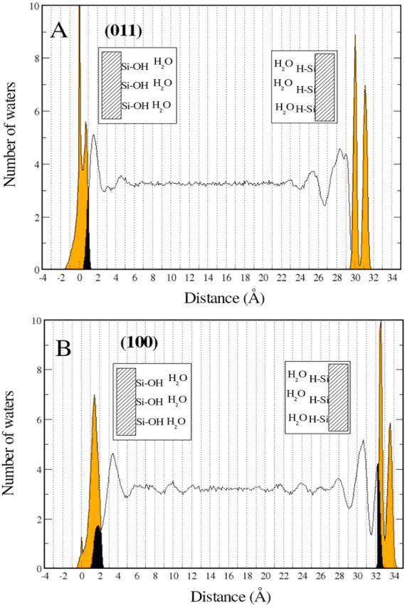
Density profiles for water adsorbed on quartz. Orange represents the surface hydrogen atoms and the black areas mark the layers where surface hydrogen atoms coexist with water oxygens.
The density profile of water changes more dramatically when in contact with the (100) quartz surface (Figure 7B). On the hydrophilic side there is a significant penetration of water in the interstices formed by the surface hydroxyls. These waters form a distinct first layer although its density is about half of that of the bulk phase (black region on the bottom left of Figure 7). Contrary to (011), the region of strong accumulation of waters is not contiguous to the hydroxyl hydrogen atoms layer, but occurs at about 2 Å away. The regions of accumulation and depletion are more extensive than on (011) and water only reaches its bulk density 12 Å from the hydroxyl hydrogen layer. The profile close to the hydrophobic side of (100) is similar to the hydrophilic side with water reaching its bulk density 13 Å from the last hydride layer. This result is extremely interesting since we have roughly the same profiles for surfaces of completely different nature. This prompted us to look at the microscopic interactions between water molecules and the way they are disrupted by the different surfaces.
To summarize, two distinct effects on the slabs of water have to be explained. One is the existence of the interstitial waters (black shaded areas in Figure 7). The second is the position of the first accumulation layers in relation to the silanol and silane surface groups. A qualitative explanation is given next in terms of the geometrical properties of the two quartz surfaces. Shown in Figure 8 are probability densities of the surface silanol oxygen atoms. The density of the surface silanes follows a similar pattern. On quartz (011) (Figure 8A) the density of silanol groups is much higher than on quartz (100) (Figure 8B), leaving fewer gaps into which water can diffuse. On quartz (011) only on the hydrophilic face is there significant overlap between water and quartz slabs and it is due to formation of H-bonds between surface hydroxyls and water molecules. On the hydrophobic side, water is repelled away from the surface by the silane groups, building up a large accumulation layer nearly 3 Å wide (Figure 7A). The situation on quartz (100) is reversed. The distribution of surface groups allows for sufficiently large areas into which water molecules can adsorb onto the surface. On the hydrophilic face this originates the distinct black peak on Figure 7. Water is able to occupy the void spaces bounded by the protruding silanols. Interstitial waters are then stabilized by water-water and silanol-water H-bonds. On the hydrophobic face the inter-penetration of water molecules is smaller, but still enough to show some overlap with the surface hydrides. The peak is narrower than on the hydrophilic surface because the surface is water repellent and waters can only be stabilized by water-water H-bonds while simultaneously avoiding surface-water interactions. This leads to fewer waters inside the cavities. The position of the first accumulation peaks at less than 3 Å from the surface silanols in both surfaces and is an indirect indication for the existence of silanol-water H-bonds. A more quantitative picture is given below in Section 4.4 where the nature and distribution of water H-bonds is analyzed.
Figure 8.
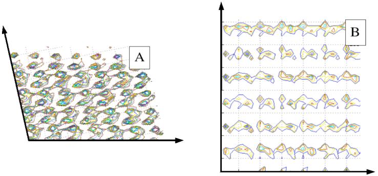
Probability density of surface silanol groups for quartz (011), A, and quartz (100), B.
4.3 Space and time correlation of water. The Van Hove self correlation function
More insight into the effects of quartz surfaces on adsorbed water can be obtained by analyzing the correlation in the positions of the same atom at different times. This is done with the help of the Van Hove self-correlation function, Gs(r,t), a function introduced by Van Hove51 which is defined as
| (2) |
The physical interpretation of the Van Hove correlation function is that 4πr2Gs(r,t)dr gives the probability of finding a particle in a volume element around the point r at time t, given that the same particle was at the origin at time t=0. Formula 2 can be evaluated directly from MD simulations. The dependence of the Van Hove self-correlation function (VHSCF) for water adsorbed on the hydrophilic faces of quartz (011) and quartz (100) are shown for t = 20 ps (plot of 4πr2Gs(r,20)) in Figure 9.* The calculations were performed for selected slabs measured from the quartz faces. The influence of the surfaces on water is clear for both surfaces and on the 20 ps timescale the mobility of water follows the same pattern for both surfaces. The stratification of water is again evident. Waters that at time t = 0 ps fill the interstices of quartz (100) or are in the first layer when adsorbed on quartz (011) (i.e. those between 0-2 Å or 0-3 Å, respectively) are the slowest. The maximum of the VHSCF for these waters occurs at approximately 7 Å and progressively increases to larger distances upon moving to the bulk phase. The explanation for this behavior is based on the ability of the surface silanol groups to interact with water molecules through formation of silanol-water H-bonds (see Table 2 of Section 4.4 for the average number of silanol-water and water-water H-bonds per oxygen atom).
Figure 9.
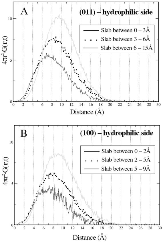
VHSCF for water adsorbed on the hydrophilic surfaces of quartz (011) (A) and quartz (100) (B) at t = 20 ps. Each plot corresponds to a layer of water.
Table 2.
Average number of water-water and silanol-water H-bonds per water in different slabs
| Quartz (011) | Quartz (100) | ||||
|---|---|---|---|---|---|
| Slab | HOH···OH2 | (Si)O-H···OH2 | Slab | HOH···OH2 | (Si)O-H···OH2 |
| 0-3 Å | 1.172 | 0.472 | 0-2 Å | 0.686 | 1.032 |
| 3-6 Å | 1.662 | 0.003 | 2-5 Å | 1.341 | 0.348 |
| 27-30 Å | 1.616 | na | 5-9 Å | 1.646 | 0.000 |
| 24-27 Å | 1.642 | na | 31.5-33 Å | 1.465 | na |
| 21-24 Å | 1.641 | na | 29-31.5 Å | 1.612 | na |
| 25-29 Å | 1.640 | na | |||
na: not applicable
The peaks for the outermost slabs, between 6 and 15 Å on quartz (011) and between 5 and 15 Å on quartz (100) (see Figure 7) occur between 9 and 10 Å in both cases. Interesting is the behavior of water in the 2 to 5 Å slab of the quartz (100) system. Recalling the plot of the density distribution of waters, shown in Figure 7, the 2-5 Å layer of quartz (100) resembles the 0-3 Å slab adjacent to quartz (011). Both slabs constitute the first accumulation layer in contact but outside quartz and both have their maximum at approximately 2 Å from quartz. However, significant differences exist between the two slabs. Waters in the immediate vicinity of quartz (011) are much more restrained than waters inside the 2-5 Å slab on the quartz (100) system. In agreement with results presented below, namely the analysis of the H-bonded patterns of water in the different slabs (see Section 4.4) the explanation relies on the differential ability of water molecules to form silanol-water H-bond interactions with the surface. For the quartz (011) system, waters in the 0-3 Å are the first layer of water molecules and can form water-silanol H-bonds with the surface. Table 2 (Section 4.4) shows that 29% of the H-bonds formed by oxygen atoms in this slab are to silanol groups. On the other hand, quartz (100) allows water to fill the interstices formed by the surface silanols and water molecules in the 2-5 Å shell are the second layer of waters. The vast majority of silanol-water H-bonds are to the interstitial waters leaving waters in the 2-5 Å slab free from surface interactions. The behavior in the outermost layers, 6 to 15 Å and 5 to 15 Å for the quartz (011) and quartz (100) systems, respectively, is very similar. The peak of both curves occurs at the same distance and the curves are virtually identical.
4.4 Microstructure of water. Effects on the H-bond network
The effect of the surfaces on the microstructure of water, particularly on the H-bond structure, is analyzed in this section. From previous sections it has emerged that water in contact with quartz has significantly different properties than in the bulk phase and that this behavior differs for the two surfaces. The present section is aimed at investigating the molecular arrangements and interactions responsible for this behavior. The single most important factor for the structure and properties of liquid water is the network of H-bonds in which the water molecules participate. Two water molecules are considered to be H-bonded if the separation of the oxygen atoms is less than 3.5 Å and the O···O-H angle is less than 30°.52,53 The first coordination shell of water, as measured by its oxygen-oxygen radial distribution functions, extends to approximately 3.5 Å.54
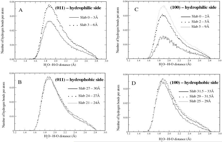
Although not part of the definition above, the H2O···H-OH separation is the simplest and most intuitive quantity to look at when investigating the properties of H-bonded waters. Shown in Figure 10 are distributions of water-water H-bond distances for quartz (011) and (100). The water slabs are divided into layers corresponding roughly to the areas of accumulation and depletion closer to the surfaces (Figure 7). The distributions are normalized to the number of waters contained in each slab, such that the height of each distribution function is proportional to the number of H-bonds formed by each water oxygen atom. In Figure 10 the upper panels are for water adsorbed on the all silanol faces and the lower panels are for adsorption on the hydrophobic (Si-H) surfaces. As may be seen in Figure 10A and B (quartz (011) system) the distributions of H2O···H-OH distances are almost identical for all layers, the only significant difference being the height of the plot for the innermost slab that is significantly lower than the others. This is an indication of competitive H-bond formation between surface silanols and nearby water molecules. Analysis of water adsorbed on quartz (100) shows the same effects, only magnified (see Figure 10C and Figure 10D). For waters in the innermost layer on the hydrophilic side the height of the H2O···H-OH distance plot is much lower and the peak is broader than for the outer layers. On the hydrophobic face the shapes of the H2O···H-OH distributions for the three layers are very similar although the height of innermost layer is noticeably smaller. These observations prompted a careful analysis of the causes. Table 2 shows the average number of water-water H-bonds per water for each of the slabs and the results are totally consistent with the qualitative observations of Figure 10. For the innermost layers on the silanol covered faces of the two systems there are significant numbers of (Si)O-H···OH2 H-bonds. For quartz (100) these interactions comprise the majority of H-bonds in which water molecules participate. In Section 4.2 the deeper penetration of water molecules in the interstitial spaces between the surface groups, either silanols or silanes, in quartz (100) was noted as compared to quartz (011). This is possible because, as noted in Figure 8, there are void spaces big enough that can be filled by water molecules. Competitive formation of silanol-water H-bonds for both systems, enhanced by diffusion and concentration of water molecules in the interstitial spaces between the surface silanol groups on quartz (100), is responsible for the different heights observed on the H2O···H-OH distances. These phenomena do not impart any changes on the shapes of the distributions. The peaks are sharp and the majority of the H2O···H-OH distances fall between 1.7 and 2.2 Å. A molecular picture of the arrangement of the water molecules in contact with the surfaces is given in Figure 11. It shows the positions of waters and quartz slabs in the last frame of the simulations. The filling of the void spaces is evident in the quartz (100) surface (Figure 11B).
Figure 10.
Distribution of water-water H-bond separations H2O···H-OH for waters adsorbed on quartz (011) (A and B) and quartz (100) (C and D). Each plot corresponds to a different layer, measured from the quartz surfaces. The top and bottom drawings are for water adsorbed on the hydrophilic and hydrophobic sides, respectively. The plots are normalized to the total number of waters in each slab.
Figure 11.
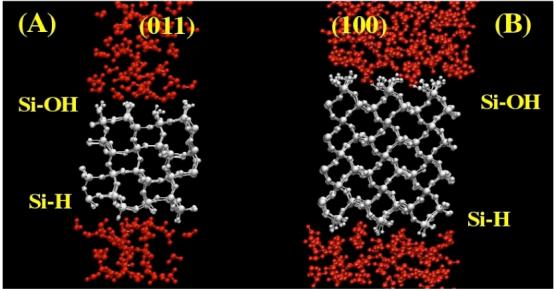
Snapshot of the last frame of the MD simulations for both (011), left drawing - A, and (100), right drawing -B. The penetration of waters in the void spaces created on the quartz surfaces is visible, particularly on quartz (100).
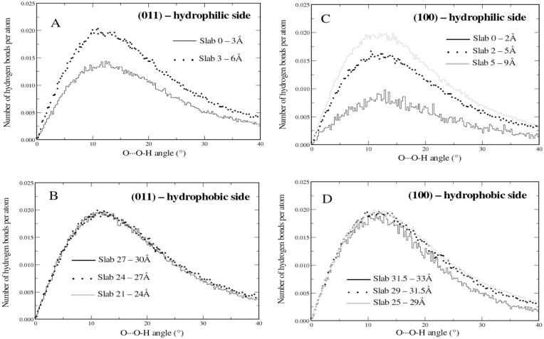
Another way to investigate the interactions between surface atoms and water and between water molecules themselves is by looking at the distribution of the O···O-H angles. As may be seen in Figure 12A and B the distribution for waters adsorbed on quartz (011) has similar shapes for the hydrophilic and hydrophobic faces. The height of the innermost water layer, represented by the black continuous line, between 0 and 3 Å on the hydrophilic side, is considerably lower than when moving towards the bulk phase layers. The effect was also observed on the distribution of the H2O···H-OH distances distribution and corresponds to the formation of H-bonds between water and the silanol groups on the surface. On the hydrophobic side water molecules cannot be stabilized by interaction with surface silanol groups so the distribution of O···O-H angles between waters is virtually identical in all layers, corresponding to having a constant number of water-water hydrogen bonds per oxygen atom (see Table 2). The plot of the distribution of O···O-H water-water H-bond angles for water adsorbed on quartz (100) is shown in Figure 12C and D. On the hydrophilic side the layer of water between 0 and 2 Å has fewer water-water H-bonds and the curve representing it is much lower than for other slabs as a consequence of formation of water-silanol H-bonds. For the next two layers considered, between the 2 to 5 Å and 5 to 9 Å shells, the distribution of O-H···O H-bond angles steadily increases to values similar to those observed on the (011) surface and the average number of water-water H-bonds per oxygen reaches its bulk value. On the hydrophobic side the behavior is similar to that observed on the hydrophobic side of quartz (011), although the curve for the first peak is slightly smaller than the next ones. The explanation relies on the geometric characteristics of the surface and on the interstitial diffusion of some water molecules between the Si-H groups. The average number of water-water H-bonds per water oxygen is slightly smaller than on the other slabs as a consequence of the geometric constraints that hinder formation of some H-bonds (see Table 2).
Figure 12.
Distribution of water-water H-bond angles, O···O-H, for waters adsorbed on quartz (011) (left) and quartz (100) (right). Each plot corresponds to a different layer, measured from the quartz surfaces. The top and bottom drawings are for water adsorbed on the hydrophilic and hydrophobic sides, respectively. Each plot is normalized to the total number of waters in each slab and its area is proportional to the number of water-water H-bonds per atom.
The combined analysis of the distance and O···O-H angle distributions for waters in different slabs reveals a remarkable uniformity. Apart from differences in the height of the curves, which are related to the average number of H-bonds per water, the vast majority follow the geometric criteria to be considered H-bonds. This is evidenced by the fact that most of the H2O···H-OH distances occurr between 1.7 and 2.2 Å, with the maxima occurring at 1.9 Å. The O-H···O angles are distributed between 7 and 20° with the peak occurring at approximately 12°.
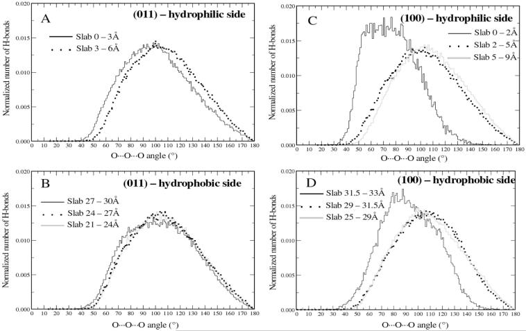
The local arrangement of water molecules was also analyzed by looking at the distribution of O···O···O angles between waters. Results are given in Figure 13 for water adsorption on quartz (011) and quartz (100). Analysis of the distribution of O···O···O angles gives a better assessment of the geometrical constraints imposed on the water molecules, for example when in close contact with the surfaces, since it spans a larger area and is more likely to change. The curves are normalized to the total number of angles present in each shell, so they have approximately the same height. For water adsorbed on quartz (011) the differences between the two layers is small, although the innermost slab is shifted towards lower angles. For water above 3 Å on the hydrophilic side and in all slabs of the hydrophobic face the distribution of O···O···O angles has its maximum at 105°, being close to the tetrahedral angle of 109.5°. For water adsorbed on quartz (100) the distribution of O···O···O angles follow a totally different pattern in the layers close to the surface. For the hydrophilic side the distribution of angles span a large range of values with similar probabilities, from 55 to 90°. On the hydrophobic side, the peak corresponding to the first shell is sharper and the maximum occurs at 85°. This is in accord with recent work where a peak corresponding to interstitial waters was found at ∼54°.50,51 Diffusion of water into the interstitial spaces on both faces of quartz (100), supplemented by formation of silanol-water H-bonds on the hydrophilic face, causes water to be spatially constrained. This effect does not show on the O-H···O angles or H2O···H-OH distances because those are less spatially sensitive. O-H···O angles and H2O···H-OH distances depend on interactions of two water molecules while O···O···O angles involve three-water interactions.
Figure 13.
Distribution of O···O···O angles for H-bonded water molecules adsorbed on quartz (011) (left) and quartz (100) (right).The curves are normalized to the total number of angles present in each shell.
5. Conclusions
The two main goals of this study were: i) optimization and presentation of a newly developed set of CHARMM force field parameters for silica and, ii) proof that it provides reliable representation of the picosecond and nanosecond dynamics of water in the vicinity of quartz crystalline surfaces using MD simulations.
An extensive series of calculations of TIP3P water confined between slabs of quartz has shown that the new parameter set for silica is able to reproduce important features of experimental neutron scattering of water confined in Vycor glasses and sol-gel silica.37,45,46 An experimental VDOS spectrum of confined water has revealed distinct features as compared with the bulk state. There is a decrease of the hindered translational peak at ∼6 meV and the broad librational peak is shifted to higher energies. Simulations with the newly developed parameters show a decrease of the rotational peak with increasingly more drastic confinement conditions as observed experimentally. However, the librational peak was found to be insensitive to confinement.
Other calculations were performed to analyze the behavior of water adsorbed on quartz on the nanosecond time scale. Two different surfaces were considered in the study, resulting from fracturing quartz along different planes: (011) and (100). Quartz (011) was modeled with single silanols on one face and single silanes on the other. Quartz (100) was modeled similarly, having geminal groups instead of single groups. The density profiles of water along the normal plane to the surface were analyzed first and yielded important results. There is some overlap between water and the hydroxyl hydrogen atoms on the hydrophilic side of quartz (011), while on the hydrophobic face water moves away from the surface and generates a large area of accumulation at approximately 1 Å from the hydrogen layer. On quartz (100) there is a significant overlap between water oxygen atoms and hydrogen atoms of silanol or silane groups in both hydrophilic and hydrophobic faces. The effect is more visible on the hydrophilic side and a distinct area of accumulation is formed. These results were explained by considering the differences in the densities of the surface groups between quartz (011) and quartz (100), the (100) allowing water molecules to migrate to the interstices formed between the surface groups. For all surfaces following an area of accumulation there is an area of depletion, becoming increasingly damped as the distance from the surface increases, before reaching the bulk state.
The structure of water was then analyzed, in particular the H-bond interactions. O···O-H and O···O···O angle distributions were plotted for different shells of water molecules close to the surfaces. Plots of (Si)O-H···OH2 bonds and O···O-H angles have similar profiles for all surfaces, with maxima at approximately 1.9 Å and 12°, respectively. The height of both plots is related to the number of H-bonds per water and in the first shell they can form fewer H-bonds than other waters in outer layers. Competing formation of H-bonds to surface atoms or impossibility of forming H-bonds at all due to geometric restrictions is the reason. The O···O···O profiles indicate that intermolecular water assumes a tetrahedral arrangement in all cases except for the first layer of each surface where there is significant diffusion into the surface interstices or strong H-bond interactions to surface atoms occurs. In these cases the O···O···O angle is significantly lower than the ideal tetrahedral value of 109°. The most evident effect occurs on hydrophilic quartz (100) and parallels the experimental results for water in confinement.
The dynamic properties of confined water were investigated through analysis of the Van Hove self-correlation function. Water in shells closer to the surface travel smaller distances for t = 20 ps according to the plot of 4πr2Gs(r,20)) in Figure 9. This is the result of increased difficulty to break H-bonds to the surface atoms or even leave the confinement areas.
Supplementary Material
Acknowledgements
Support from the CDC 200-2000-08026 and NIH GM51501 are acknowledged and PEML appreciates financial support from CDC. The findings and conclusions in this report are those of the authors and do not necessarily represent the views of the National Institute for Occupational Safety and Health.
Abbreviations
- VDOS
Vibrational Density of States
- HF
Hartree-Fock
- LJ
Lennard-Jones
- MD
molecular dynamics
- QM
quantum mechanics
- VDW
van der Waals
- H-bond
hydrogen bond
- VHSCF
Van Hove Self Correlation Function
Footnotes
Since natural ventilation of the lung is driven by only small gas pressures (not more than ±10 cm of H2O or 1 ± 0.0003 atm) microscopic simulations carried out at constant pressure of 1 atm represent the most appropriate modeling approach.
At t=20 ps.the effect of the surfaces on the properties of adsorbed water is clearly observed.
References
- (1).Monographs on the evaluation of the carcinogenic risk of chemical to humans: silica, some silicates, coal dust and para-aramid fibrils. Vol. 68. IARC; 1997. [PMC free article] [PubMed] [Google Scholar]
- (2).Harington JSS. Afr. Med. J. 1963:451. [PubMed] [Google Scholar]
- (3).Nash T, Alison AC, Harington JS. Nature. 1966;210:259. doi: 10.1038/210259a0. [DOI] [PubMed] [Google Scholar]
- (4).Wallace WE, Vallyathan V, Keane MJ, Robinson V. J. Tox. Env. Health. 1985;16:415. doi: 10.1080/15287398509530751. [DOI] [PubMed] [Google Scholar]
- (5).Dolgner R, Brockhaus AS,HW. Grundfragen Silikoseforsch. 1963;19:213. [PubMed] [Google Scholar]
- (6).Le Bouffant L,D,H, Martin JC. The therapeutic action of aluminium compounds on the development of experimental lesions produced by pure quartz or mixed dust. In: Walton WH, editor. Inhaled Particles. IV. Pergamon Press; Oxford: 1977. p. 389. [PubMed] [Google Scholar]
- (7).Aronova GV, Velichkovskii BT, Zykova VA, El’nichnykh LN. Gig. Tr. Prof. Zabol. 1987;12:24. [PubMed] [Google Scholar]
- (8).Aronova GV, Velichkovskii BT, Katsnel’son BA, Belobragina GV, Starkov PS, Bezzabotnova LV. Gig. Sanit. 1967;32:12. [PubMed] [Google Scholar]
- (9).Vallyathan V, Kang JH, Van Dyke K, Dalal NS, Castranova V. J. Tox. Env. Health. 1991:303. doi: 10.1080/15287399109531529. [DOI] [PubMed] [Google Scholar]
- (10).Murashov VV, Leszczynski J. J. Phys. Chem. A. 1999;103:1228. [Google Scholar]
- (11).Chunbo Y, Daqing Z, Aizhuo L, Jiazuan N. J. Colloid Interface Sci. 1995;172:536. [Google Scholar]
- (12).Castranova V. Inhal. Tox. 2000;12:7. doi: 10.1080/08958378.2000.11463226. [DOI] [PubMed] [Google Scholar]
- (13).Wang LY, Antonini JM, Rojanasakul Y, Castranova V, Scabilloni JF, Mercer RR. J. Cell Physiol. 2003;194:215. doi: 10.1002/jcp.10220. [DOI] [PubMed] [Google Scholar]
- (14).Das AR, Cilento EV, Keane MJ, Wallace WE. Inhal. Tox. 2000;12:765. doi: 10.1080/08958370050085183. [DOI] [PubMed] [Google Scholar]
- (15).Bruch J, Rehn S, Rehn B, Borm P, Fubini B. Int J Hyg Envir Heal. 2004;207:203. doi: 10.1078/1438-4639-00278. [DOI] [PubMed] [Google Scholar]
- (16).Murashov VV, Harper M, Demchuk E. Env. Heath Persp. submitted. [Google Scholar]
- (17).Sindorf DW, M. GE. J. Phys. Chem. 1982;86:5208. [Google Scholar]
- (18).Fyfe CA, Gobbi CG, Kennedy GJ. J. Phys. Chem. 1985;89:277. [Google Scholar]
- (19).Schlegel ML, Nagy KL, Fenter P, Sturchio NC. Geochim. Cosmochim. Acta. 2002;66:3037. [Google Scholar]
- (20).Tsuneyuki S, Tsukada M, Aoki H, Matsui Y. Phys. Rev. Lett. 1988;61:869. doi: 10.1103/PhysRevLett.61.869. [DOI] [PubMed] [Google Scholar]
- (21).Vanbeest BWH, Kramer GJ, Vansanten RA. Phys. Rev. Lett. 1990;64:1955. doi: 10.1103/PhysRevLett.64.1955. [DOI] [PubMed] [Google Scholar]
- (22).Hill JR, Sauer J. J. Phys. Chem. 1994;98:1238. [Google Scholar]
- (23).Schroder KP, Sauer J. J. Phys. Chem. 1996;100:11043. [Google Scholar]
- (24).Demiralp E, Cagin T, Goddard WA. Phys. Rev. Lett. 1999;82:1708. [Google Scholar]
- (25).Herzbach D, Binder K, Muser MH. J. Chem. Phys. 2005;123 doi: 10.1063/1.2038747. [DOI] [PubMed] [Google Scholar]
- (26).Brooks BR, Bruccoleri RE, Olafson BD, Sates DJ, Swarninathan S, Karplus M. J. Comp. Chem. 1983;4:187. [Google Scholar]
- (27).MacKerell AD, Jr., Brooks B, Brooks CL, III, Nilsson L, Roux B, Won Y, Karplus M. CHARMM: The Energy Function and Its Paramerization with an Overview of the Program. In: Schleyer P. v. R., Allinger NL, Clark T, Gasteiger J, Kollman PA, Schaefer HF, III, Schreiner PR., editors. Encyclopedia of Computational Chemistry. Vol. 1. John Wiley & Sons; Chichester: 1998. p. 271. [Google Scholar]
- (28).Frisch MJT,GW, Schlegel HB, Scuseria GE, Robb MA, Cheeseman JR, Zakrzewski VG, Montgomery JA, Jr., Straunann RE, Burant JC, Dapprich S, Millam JM, Daniels AD, Kudin KN, Strain MC, Farkas O, Tomasi J, Barone V, Cossi M, Cammi R, Mennucci B, Pomelli C, Adamo C, Clifford S, Ochterski J, Petersson GA, Ayala PY, Cui Q, Morokuma K, Malick DK, Rabuck AD, Raghavachari K, Foresman JB, Cioslowski J, Ortiz JV, Baboul AG, Stefanov BB, Liu G, Liashenko A, Piskorz P, Komaromi l., Gompetts R, Martin RL, Fox DJ, Keith T, AI-Laham MA, Peng CY, Nanayakkara A, Gonzalez C, Challacombe M, Gill PMW, Johnson B, Chen W, Wong MW, Andres JL, Gonzalez C, Head-Gordan M, Replogle ES, Pople JA. Gaussian 98. Gaussian, Inc.; Pittsburgh, PA: 1998. [Google Scholar]
- (29).Foloppe N, MacKerell AD. J. Comp. Chem. 2000;21:86. [Google Scholar]
- (30).Iler RK. The chemistry of silica: solubility, polymerization, colloid and surface properties, and biochemistry. Wiley; New York: 1979. [Google Scholar]
- (31).Berendsen HJC, Postma JPM, Gunsteren W. F. v., DiNola A, Haak JR. J. Chem. Phys. 1984;81:3684. [Google Scholar]
- (32).Steinbach PJ, Brooks BR. J. Comp. Chem. 1994;15:667. [Google Scholar]
- (33).Ryckaert JP, Ciccotti G, Berendsen HJC. J. Comp. Phys. 1977;23 [Google Scholar]
- (34).Allen MPT,DJ. Computer Simulation of Liquids. Oxford University Press; New York: 1989. [Google Scholar]
- (35).Martyna GJ, Klein ML, Tuckerman M. J. Chem. Phys. 1992;97:2635. [Google Scholar]
- (36).Mackerell AD. J. Comp. Chem. 2004;25:1584. doi: 10.1002/jcc.20082. [DOI] [PubMed] [Google Scholar]
- (37).Bellissentfunel MC, Chen SH, Zanotti JM. Phys. Rev. E. 1995;51:4558. doi: 10.1103/physreve.51.4558. [DOI] [PubMed] [Google Scholar]
- (38).Bellissent-Funel MC. Eur. Phys. J. E. 2003;12:83. doi: 10.1140/epje/i2003-10023-9. [DOI] [PubMed] [Google Scholar]
- (39).Ramsay JDF, Poinsignon C. Langmuir. 1987;3:320. [Google Scholar]
- (40).Bellissentfunel MC, Lal J, Bosio L. J. Chem. Phys. 1993;98:4246. [Google Scholar]
- (41).Takamuku T, Yamagami M, Wakita H, Masuda Y, Yamaguchi T. J. Phys. Chem. B. 1997;101:5730. [Google Scholar]
- (42).Smirnov P, Yamaguchi T, Kittaka S, Takahara S, Kuroda Y. J. Phys. Chem. B. 2000;104:5498. [Google Scholar]
- (43).Crupi V, Majolino D, Migliardo P, Venuti V. J. Phys. Chem. A. 2000;104:11000. [Google Scholar]
- (44).Venuti V, Crupi V, Magazu S, Majolino D, Migliardo P, Bellissent-Funel MC. Journal de Physique IV. 2000;10:211. [Google Scholar]
- (45).Zanotti JM, Bellissent-Funel MC, Chen SH. Phys. Rev. E. 1999;59:3084. [Google Scholar]
- (46).Crupi V, Majolino D, Migliardo P, Venuti V, Bellissent-Funel MC. Mol. Phys. 2003;101:3323. [Google Scholar]
- (47).Bruni F, Ricci MA, Soper AK. J. Chem. Phys. 1998;109:1478. [Google Scholar]
- (48).Soper AK, Bruni F, Ricci MA. J. Chem. Phys. 1998;109:1486. [Google Scholar]
- (49).Drake JM, Klafter J. Physics Today. 1990;43:46. [Google Scholar]
- (50).Raviv U, Laurat P, Klein J. Nature. 2001;413:51. doi: 10.1038/35092523. [DOI] [PubMed] [Google Scholar]
- (51).Van Hove L. Phys. Rev. 1954;95:249. [Google Scholar]
- (52).Ferrario M, Haughney M, McDonald IR, Klein ML. J. Chem. Phys. 1990;93:5156. [Google Scholar]
- (53).Luzar A, Chandler D. J. Chem. Phys. 1993;98:8160. [Google Scholar]
- (54).Soper AK, Phillips MG. Chem. Phys. 1986;107:47. [Google Scholar]
Associated Data
This section collects any data citations, data availability statements, or supplementary materials included in this article.


