Abstract
Anteroposterior radiographs that included the whole tibia were taken before and after 75 total knee arthroplasties in 48 patients. The same tibial extra-medullary alignment guide system was used in every knee. The average tibial component alignment was 0.4 (SD 2.5, range −4.9 to 6.4) degrees of valgus post-operatively. 59 tibial components (78.7%) had a tibial cut within 3 degrees from being perpendicular to the mechanical axis, ten were too valgus (13.3%) and six were too varus (8%). The chance of the tibial components becoming too varus was higher if there was lateral tibial bowing, compared with no tibial bowing (p = 0.048). A smaller lateral width of the leg increased the chance of the tibial components becoming too valgus (p = 0.047).
Résumé
Les radiographies face/profil de tout le tibia ont été analysées après la mise en place de 75 prothèses totales du genou chez 48 patients. L’axe tibial a été analysé selon le même système d’alignement extra médullaire. La moyenne de l’alignement tibial a été de 0.4 degrés de valgus en post-opératoire (2.5 SD de 4.9 à 6.4), 59 composants tibiaux (78.7%) ont été positionnés avec une coupe tibiale de 3 degrés par rapport à l’axe mécanique. 10, présentaient un valgus plus important (13.13%) et 6 un varus plus important (8%). La courbure tibiale majore l’implantation du composant tibial en varus (p = 0.048). Un petit tibia dans le plan frontal augmente les chances d’un positionnement du composant tibial en valgus (p = 0.047).
Introduction
In total knee arthroplasty (TKA), the tibial bone cut is usually made perpendicular to the mechanical axis in the coronal plane. To accomplish this, most TKA system manufacturers provide both the extra-medullary (EM) and intra-medullary (IM) alignment guides. We prefer to use the EM alignment guide, because we feel that the tibial medullary canals of our patients are often bowed. It has been reported that the IM alignment guide would result in unacceptable tibial cut because of tibial bowing in 22% of Chinese patients who had varus arthritic knees [4].
In this paper, we assess the accuracy of the tibial EM alignment guide. We investigate whether the pre-operative knee deformity, length of the tibia, width of the leg that indicates soft tissue bulk laterally and medially, and the pattern of tibial bowing in the coronal plane would affect the accuracy.
Patients and methods
From July 2000 to June 2001, anteroposterior (AP) standing radiographs of the entire lower limbs including the hips, knees and ankles in one single film were taken before and after 100 consecutive TKA performed at our institution. The radiographs were found to be suboptimal in 25 knees, either because of excessive limb rotation as judged by the bony landmarks in the femur or tibia, or the hip or ankle was not clearly visualised in the radiograph. The radiographs in the other 75 knees from 48 patients were properly taken and considered to be suitable for analysis. There were 8 men and 40 women. Twenty-seven patients had one-stage, sequential bilateral total knee replacements. The average age was 64.3 (SD 10.4, range 33–81) years. There were 37 left and 38 right knees. The diagnoses were osteoarthritis in 65 knees, rheumatoid arthritis in six knees, ankylosing spondylitis in two knees and haemophilia in two knees. The radiographs were scanned using VXR-12 plus film digitiser (VIDAR, Denmark). The digital images were measured using a commercial software specifically designed for radiographic measurements (Imagika Version 1.01, Clinical Management Corporation, New Jersey, USA).
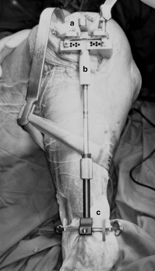
A single type of prosthesis was used in all patients (Low Contact Stress LCS, rotating platform, Depuy, Johnson and Johnson, Leeds, UK). The operations were performed by the same team of surgeons using the same routines. When the lower limb was prepared and draped, we made sure that all anatomical landmarks over the ankle were clearly palpable. The knee was approached in the conventional manner, the patella was everted laterally, and retractors were placed posteriorly and laterally to expose the whole tibial plateau. The Milestone instruments were used for all the TKA (Fig. 1). To guide the proximal tibial bone cut, an EM alignment guide rod was used. Two short spikes anchored the upper end of the guide rod over the insertion footprint of the anterior cruciate ligament over the tibial plateau. The rotation was set by putting the rod anterior to the junction of the medial one-third and middle one-third of the tibial tuberosity. Over the ankle, the rod was positioned using a spring device, with the distal end of the rod being placed anterior to the tibialis anterior tendon. The proximal tibial cutting jig was then connected to the proximal part of the rod. An outrigger with a long perpendicular rod could be connected to the cutting jig for the surgeon to verify its varus-valgus alignment.
Fig. 1.
The upper end of the Milestones alignment guide (a) was fixed by two short spikes over the tibial plateau. The rotation was set by putting the rod anterior to the junction of the medial one third and middle one third of the tibial tuberosity (b). The distal end of the rod (c) was placed anterior to the tibialis anterior tendon
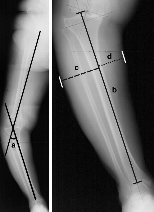
We measured four parameters in the pre-operative radiograph (Fig. 2). The first parameter was pre-operative knee deformity. This was taken as the angle subtended by a line drawn from the centre of the femoral head to the intercondylar notch over the distal femur (mechanical axis of the femur) and a line drawn from the midpoint between the two tibial eminences to the midpoint of the talar dome (mechanical axis of the tibia). The second parameter was the tibial length. This was measured along the tibial axis from the tibial plateau to the tibial plafond. The third parameter was the lateral width of the leg that reflected the soft tissue bulk laterally. The most lateral point of the soft tissue shadow was identified, and the perpendicular distance from the line drawn along the tibia was then measured. The fourth parameter was the medial width of the leg. It was the perpendicular distance between the most medial point of the soft tissue shadow of the leg and the line drawn along the tibia.
Fig. 2.
Four parameters were measured on the pre-operative radiograph: the knee deformity (left, angle a), the length of the tibia (right, solid line b), the lateral width of the leg (right, interrupted line c) and the medial width of the leg (right, dotted line d)
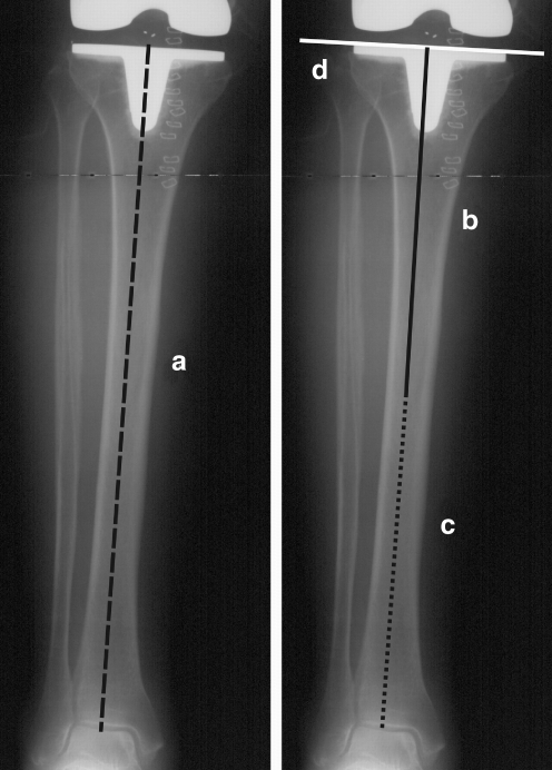
We drew four lines on the post-operative radiograph (Fig. 3). The first line was the mechanical axis of the tibia; it was the line that joined the centre of the proximal tibia and the midpoint over the dome of the talus. The second was the axis of the proximal tibia diaphysis; it was the line that best described the midpoints of the endosteal canal from the tibial cut surface to the mid diaphysis. The third was the axis of the distal tibial diaphysis; it was the line drawn from the midpoint over the dome of the talus to the midpoint of the endosteal cavity at the mid diaphysis. The fourth was the proximal tibial line; it was drawn tangential to the tibial component metal base plate. The deviation of the proximal tibial line from perpendicular to the mechanical axis was measured in the post-operative radiograph. This represented the varus-valgus alignment of the tibial component after TKA. If the axes of the proximal and distal diaphysis formed an angle that was more than 2 degrees, tibial bowing was considered to be present. When the distal axis angulated towards the midline relative to the proximal axis, the tibia had a lateral bow; when the distal axis angulated away from the midline relative to the proximal axis, the tibia had a medial bow.
Fig. 3.
Four lines were drawn on the postoperative radiograph: the mechanical axis (left, black interrupted line a), the anatomical axis of the proximal tibial diaphysis (right, black solid line b), the anatomical axis of the distal tibial diaphysis (right, black dotted line c) and the proximal tibial line (right, white solid line d)
The data was analysed using statistical software (SPSS 12.0 for Windows, Chicago, Illinois, USA). Pearson correlation coefficients were computed to find out whether pre-operative knee deformity, tibial length, widths of the leg and bowing of the tibial diaphysis in the coronal plane had any relationship with the accuracy of the varus-valgus alignment of the tibial component. The pre-operative deformity angles and lateral widths of the legs for tibial components that were in varus, acceptable and in valgus were compared using independent t-tests. The relationship between the varus-valgus alignment of the tibial component and whether the knee was in varus or valgus before TKA, and that between the tibial bowing in the coronal plane and the varus-valgus alignment of the tibial component was further evaluated using the chi-square tests. Statistical significance was assumed if the p-value was less than 0.05.
Results
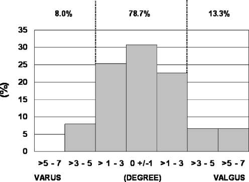
The tibial component was in 0.4 (SD 2.5, range −4.9 to 6.4) degrees of valgus from the perpendicular to the mechanical axis. If acceptable alignment was defined as within 3 degrees of the perpendicular to the mechanical axis [5], the tibial components were in acceptable positions in 59 knees (78.7%), too valgus in ten knees (13.3%) and too varus in six knees (8%). The distribution of the varus-valgus alignment of the tibial component is depicted in Fig. 4.
Fig. 4.
The tibial component alignment after TKA
The pattern of tibial bowing in the coronal plane significantly affected the varus-valgus alignment of the tibial component after TKA (p = 0.008). If there was no tibial bowing (43 tibiae, 57.3%), the tibial component was in a mean of 0.5 (SD 2.3, range −2.4 to 6.4) degrees of valgus after TKA. If there was lateral bowing (22 tibiae, 29.3%), the tibial component alignment averaged 0.7 (SD 2.4, range −4.9 to 4.6) degrees of varus. The difference was significant (p = 0.048). If there was medial tibial bowing (ten tibiae, 13.3%), the tibial component was in a mean of 1.8 (SD 2.7, range −3.1 to 5.5) degrees of valgus. The difference in the tibial component alignment between the knees with medial tibial bowing and those without tibial bowing was insignificant (p = 0.18).
The lateral width of the leg averaged 63 mm (SD 8, range 33–87 mm). The average lateral widths of the leg were 57 mm (SD 10, range 33–69 mm) for the tibial components that were too valgus after TKA, and 64 mm (SD 8, range 49–87 mm) for those that had acceptable position. The difference was significant (p = 0.047). The average lateral width of the leg was 64 mm (SD 7, range 53 to 76) for those that were too varus. The difference in the lateral widths of the leg between the tibial components that were too varus and those that were acceptable after TKA was insignificant (p = 0.92).
The pre-operative knee deformity averaged 11.4 (SD 9.4, range −20 to 35) degrees of varus. For the eight knees that were in valgus before TKA, one tibial component was too varus, four were acceptable and three were too valgus after TKA. For the 67 knees that were in varus before TKA, five tibial components were too varus, 55 were acceptable and seven were too valgus after TKA. The difference did not reach statistical significance (p = 0.08).
The length of the tibia averaged 334 mm (SD 25, range 277–395). The medial width of the leg averaged 41 mm (SD 8, range 26–63). These two dimensions did not show significant correlation with the varus-valgus alignment of the tibial component after TKA.
Discussion
Several groups have compared the accuracy of the tibial cuts achieved with the use of the EM and IM tibial alignment guides. Brys et al. [2] in 1991 studied 52 IM guided and 62 EM guided TKA. A tibial cut within 2 degrees of the perpendicular to the mechanical axis was achieved in 94% of the IM guided knees and 85% of the EM guided knees. Ishii et al. [3] in 1995 reported that equal percentages (88%) of tibial components fell within 4 degrees of the perpendicular to the mechanical axis after 50 IM guided and 50 EM guided TKA. Teter et al. [9] in 1995 measured the tibial component alignment after 352 TKA. The tibial component fell within 4 degrees of perpendicular to the mechanical axis in 94% of the IM guided TKA and 92% of the EM guided TKA. Maestro et al. [7] in 1998 compared the tibial component alignment after 61 IM guided TKA and 55 EM guided TKA. The tibial component fell within 4 degrees of perpendicular to the mechanical axis in 87% of IM guided and 84% of the EM guided TKA. It appeared that the IM guide was slightly superior to the EM guide in achieving acceptable tibial bone cuts.
Teter et al. [9] analysed the errors in the IM guided knees and attributed half of the malaligned tibial components to tibial bowing in the coronal plane. The incidence was low, and occurred in 3.4% of the IM guided knees in their study. Oswald et al. [8] in 1993 analysed the radiographs of 44 post-mortem tibial specimens from normal donors. They reported that the difference between the mechanical axis and the anatomical axis of the proximal tibia was only 0.1 (SD 1.1, range −2.5 to 2.0) degrees. This implied that the IM alignment guide should produce a tibial cut perpendicular to the mechanical axis in most cases. However, this was not the case in the Asian patient population. Ko et al. [4] in 2001 analysed 72 lower limb radiographs in Chinese patients who had varus arthritic knees, and found that the mechanical axis differed from the anatomical axis of the proximal tibia by 1.8 (SD 1.4, range 0–9) degrees. The use of the IM alignment guide would result in 22% of tibial cuts being unacceptable, and this was attributed to tibial bowing. We also observed that tibial bowing in the coronal plane commonly occurred in our patient population. In our study, nearly 30% of tibiae showed lateral tibial bowing and 13% showed medial tibial bowing. We therefore prefer to use the tibial EM alignment guide for our TKA.
Teter et al. [9] commented that there was a tendency to cut the proximal tibia in varus if EM alignment guides were used. In their study, the tibial components were in an average 1 degree of varus for the IM guided TKA, and in 2.7 degrees of varus for the EM guided TKA. They attributed the errors with the use of EM alignment to difficulty in identifying the true centre of the ankle. Maestro et al. [7] attributed the suboptimal results in the EM guided knees to obesity. They suspected that it would be more difficult to palpate the landmarks around the ankle accurately, and thus the distal jig positioning was less precise.
Since landmarks over the ankle are difficult to locate with accuracy and precision, surgeons may use additional clues including visual inspection of the soft tissue silhouette of the leg and palpation of the anterior tibial crest when positioning the tibial EM alignment guide rod. These may create problems, and cause inaccuracies of the tibial bone cuts.
We found that the presence of lateral tibial bowing increased the chance of having a tibial component that was too varus after TKA. We did not expect that using the EM guide would result in the same problem as the IM guide, as the guide rod was not inserted into the bowed medullary canal. We postulated that the surgeons might wrongly adjust the EM guide rod to align it with the anterior tibial crest, not realising that the anterior tibial crest was moved laterally over the shin in the presence of lateral tibial bowing. By doing so, they changed the cutting jig position into varus.
We also found that thinner soft tissue bulk over the lateral aspect of the leg increased the chance of having a tibial component that was too valgus. We postulated that a thin layer of soft tissues over the lateral calf could give the surgeon a false impression that the tibial axis was more medially located. The surgeons might therefore wrongly adjust the EM guide rod distally and thus change the cutting jig’s position into valgus.
For legs with thicker soft tissues over the lateral calf, deliberately placing the EM rod in slight valgus may reduce the chance of having a tibial component that ended up too varus. However, we do not recommend doing so in slim legs. One should also realise that the anterior tibial crest may be situated lateral to the mechanical axis because of tibial bowing, and is thus not a reliable landmark in helping the alignment of the EM guide rod in some patients.
While the accuracy of extramedullary guides for tibial component placement could be affected by tibial bowing and thickness of soft tissues over the leg, these factors become non-issues with computer assisted TKA. In the latter, the surgeon only registers landmarks over the tibial plateau and around the ankle. Computer navigation can thus improve the tibial component alignment and minimise the outliers in lower limb alignment after TKA [1, 6].
References
- 1.Bejek Z, Sólyom L, Szendrõi M (2006) Experiences with computer navigated total knee arthroplasty. Int Orthop. DOI 10.1007/s00264-006-0254-0 [DOI] [PMC free article] [PubMed]
- 2.Brys DA, Lombardi AV Jr, Mallory TH, Vaughn BK (1991) A comparison of intramedullary and extramedullary alignment systems for tibial component placement in total knee arthroplasty. Clin Orthop 263:175–179 [PubMed]
- 3.Ishii Y, Ohmori G, Bechtold JE, Gustilo RB (1995) Extramedullary versus intramedullary alignment guides in total knee arthroplasty. Clin Orthop 318:167–175 [PubMed]
- 4.Ko PS, Tio MK, Ban CM, Mak YK, Ip FK, Lam JJ (2001) Radiologic analysis of the tibial intramedullary canal in Chinese varus knees. Implications in total knee arthroplasty. J Arthroplasty 16:212–215 [DOI] [PubMed]
- 5.Lotke PA, Ecker ML (1977) Influence of positioning of prosthesis in total knee replacement. J Bone Joint Surg 59(1):77–79 [PubMed]
- 6.Maculé-Beneyto F, Hernández-Vaquero D, Segur-Vilalta JM, Colomina-Rodríguez R, Hinarejos-Gomez P, García-Forcada I, Seral Garcia B (2006) Navigation in total knee arthroplasty. A multicenter study. Int Orthop 30:536–540 [DOI] [PMC free article] [PubMed]
- 7.Maestro A, Harwin SF, Sandoval MG, Vaquero DH, Murcia A (1998) Influence of intramedullary versus extramedullary alignment guides on final total knee arthroplasty component position. A radiographic analysis. J Arthroplasty 13:552–558 [DOI] [PubMed]
- 8.Oswald MH, Jakob RP, Schneider E, Hoogewoud HM (1993) Radiologic analysis of normal axial alignment of femur and tibia in total knee arthroplasty. J Arthroplasty 8:419–426 [DOI] [PubMed]
- 9.Teter KE, Bregman D, Colwell CW Jr (1995) Accuracy of intramedullary versus extramedullary tibial alignment cutting systems in total knee arthroplasty. Clin Orthop 321:106–110 [PubMed]


