Abstract
Digital subtraction angiography (DSA) X-ray imaging for small animals can be used for functional phenotyping given its ability to capture rapid physiological changes at high spatial and temporal resolution. The higher temporal and spatial requirements for small-animal imaging drive the need for short, high-flux X-ray pulses. However, high doses of ionizing radiation can affect the physiology. The purpose of this study was to verify and apply metal oxide semiconductor field effect transistor (MOSFET) technology to dosimetry for small-animal diagnostic imaging. A tungsten anode X-ray source was used to expose a tissue-equivalent mouse phantom. Dose measurements were made on the phantom surface and interior. The MOSFETs were verified with thermoluminescence dosimeters (TLDs). Bland-Altman analysis showed that the MOSFET results agreed with the TLD results (bias, 0.0625). Using typical small animal DSA scan parameters, the dose ranged from 0.7 to 2.2 cGy. Application of the MOSFETs in the small animal environment provided two main benefits: (1) the availability of results in near real-time instead of the hours needed for TLD processes and (2) the ability to support multiple exposures with different X-ray techniques (various of kVp, mA and ms) using the same MOSFET. This MOSFET technology has proven to be a fast, reliable small animal dosimetry method for DSA imaging and is a good system for dose monitoring for serial and gene expression studies.
Introduction
In recent years, molecular imaging has made significant progress due to the increased use of genetically altered small animal models of human disease in basic research. Concurrently, new techniques have been employed for rodent imaging, including magnetic resonance microscopy, microPET, optical imaging, micro-ultrasound and microCT. Of particular interest is X-ray digital subtraction angiography (DSA), which has the advantage of being able to capture rapid physiological changes through functional imaging while being easy to use (1). Extensive work with DSA has been done in animals and humans, ranging from initial studies first suggested by Mistretta et al. (2) in the 1970s to use as a tool for clinical diagnosis. Scaling DSA to the higher temporal and spatial resolutions needed in the mouse and rat poses challenges. Efforts to obtain the optimal X-ray spectra for the highest signal-to-noise ratio (SNR) and contrast-to-noise ratio (CNR) (3) have pointed to the use of high-flux X-ray sources with short exposure times (10 ms). On the other hand, the search for better imaging methods should consider radiation damage to the small animal. It has been reported that DNA damage can be caused by a dose as small as 1 mGy using 90 kV (4).
Current methods for small animal dosimetry have several challenges. Traditional thermoluminescence dosimetry (TLD) is a labor-intensive and time-consuming process that involves annealing, postirradiation waiting, and the reading of individual chips. Immediate results can be obtained using an ionization chamber in conjunction with the TG-61 protocol (American Association of Physicists in Medicine) (5, 6). However, inserting the ionization chamber into a live animal is physically unfeasible (the mouse is smaller than the ionization chamber). In live animals, TLDs may be invasively inserted (7); however, the procedure of inserting and extracting the dosimeter is inconvenient. This is especially true if dose measurements are needed for multiple X-ray techniques. These challenges can be overcome with the use of the metal oxide semiconductor field effect transistor (MOSFET) technology we describe in this paper. The advantages of the MOSFET system include miniature detector size (2.5 mm × 8 mm × 1.3 mm thick), prompt readout of results, and multiple dose measurement capability using multiple X-ray techniques with the same detector (8).
This study compared the MOSFET method with the standard TLD method. In the clinic, much work has already been done in this area (9, 10). In the small animal diagnostic imaging environment, this has not been studied.
Materials and Methods
X-Ray Tube
The radiographic system constructed in-house for this work included a 0.3/1.0-mm focal spot tungsten (W) rotating anode tube (SRO 0950 ROT 350, Philips Medical Systems) with a 65-kW generator (EPS 65RF, EMD Technologies, Saint-Eustach, Quebec, Canada). Tube potential settings were 45 kVp and 70 kVp, representing the low and high SNR values (3). The exposure time was kept at 10 ms to limit motion blur caused by the rapid physiological movements in the small animal. The heart rate of a mouse is of the order of 600 beats per minute. The need for very short (10 ms) exposures places a premium on very high photon flux; for this reason the maximum tube current was employed. The scan parameters were 70 kVp, 400 mA and 45 kVp, 400 mA. The typical DSA technique used for our small animal imaging consisted of a series of 30 exposures (3, 11).
Mobile MOSFET Wireless Dosimetry System
Dose measurements were made with a mobile MOSFET wireless dosimetry system (Model TN-RD-70-W, Best Medical Canada, Ottawa, Canada). The system included a Bluetooth wireless transceiver (TN-RD-38), a mobile MOSFET reader module (TN-RD-16), and three high-sensitivity MOSFET detectors (TN-1002RD). The MOSFET measured the difference in threshold voltage before and after an X-ray exposure (12). This difference in voltage was proportional to the absorbed dose. Threshold voltages were read immediately after each exposure.
MOSFET Calibration
The MOSFET detectors were calibrated at 70 and 45 kVp using two ion chambers—Radcal 6 cc (Model 10x5-6) for the 70 kVp beam and a mammographic ion chamber (Model 10x5-6M-3, Radcal) for the 45 kVp beam—together with a monitor (Model 9015, Radcal, Monrovia, CA). MOSFETs were exposed to approximately 1 R three times at the two tube potentials. The MOSFETs were placed at a source-to-dosimeter distance of 61 cm, with the epoxy bulb facing the beam. Calibration factors for each MOSFET were determined by recording detector response in millivolts (mV) and normalizing by absorbed dose (Gy). The conversion of exposure (C kg−1) to absorbed dose in soft tissue (Gy) was estimated using the f factor in Hendee's description (13), as follows:
| (1) |
where Dtissue(Gy) is the dose to soft tissue, X(C kg−1) is the ion chamber reading and ftissue(Ē) is the f factor (C kg−1-to-Gy conversion factor) at the effective energy Ē; i.e.,
| (2) |
where [(μen)m]tissue and [(μen)m]air are the mass energy absorption coefficients for the tissue and air, respectively (14). In Eq. (1), the CFchamber is the chamber correction factor (CFchamber = 1.012, for the 10x5-6 model, and CFchamber = 1.007 for the 10x5-6M-3 model, calibrated at the University of Wisconsin Dosimetry Laboratory, Madison, WI). CFtemp and CFpressure are the temperature and pressure correction factors, respectively. The Radcal model 9015 has a built-in function for automatic temperature and pressure corrections; thus no corrections were needed after data collection.
The f factors as a function of effective energy were fitted to the Boltzmann sigmoidal curve (Prism, version 4.0, GraphPad Software, San Diego, CA), which enabled us to obtain f factors at the appropriate effective energies. The beam quality (HVL) and effective energies for 70 and 45 kVp were obtained by using the data from the Institute of Physics and Engineering in Medicine (IPEM) report 78 (15). The effective energies were estimated to be 40.4 keV for 70 kVp with an f factor (cGy/R) of 0.9235 and 30.9 keV for 45 kVp with an f factor of 0.9201.
Mouse Phantom, Dose Measurement and Statistical Analysis
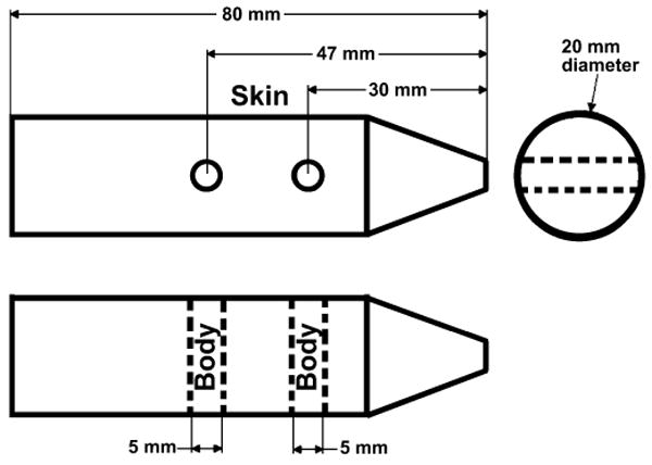
A tissue-equivalent mouse phantom (CIRS, Norfolk, VA) with a diameter of 20 mm and a length of 80 mm was placed in the X-ray beam path with its long axis perpendicular to the beam. Two holes 5 mm in diameter were drilled in two locations in the interior of the phantom, perpendicular both to its long axis and to the beam direction, to accommodate the MOSFET detectors and TLD chips as shown in Fig. 1. One MOSFET detector was placed in each hole. The phantom interior readings (body) were averaged together. The third detector was located on the surface (skin), with the bulb facing the X-ray tube. In separate runs, the MOSFET dosimetry readings were validated by TLD chips (TLD-100, Thermo Scientific, Franklin, MA). The TLDs were placed at the same mouse phantom locations as at which MOSFET measurements were made. Three MOSFET detectors measured the dose for five DSA runs (30 exposures per run) using the settings described earlier. At the same three locations, six TLD runs were made at each tube potential. The average dose and standard deviation (1σ) were calculated for both methods. All of the dose values were used to produce a Bland-Altman plot, which shows the average of the two values (MOSFET and TLD) for each location and the difference between the two measurements (Prism).
FIG. 1.

Schematic of tissue-equivalent mouse phantom. The top drawing is a side view, and the bottom is a top view (looking down). Thus the two drawings are perpendicular views to each other. The MOSFETs and TLDs were placed on the surface (skin) and interior (body) of the phantom. The phantom was aligned under X-ray guidance to be at the center of the X-ray beam path and with the dosimeters perpendicular to the imaging surface.
Results and Discussion
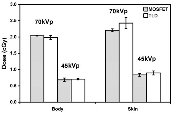
The MOSFETs were compared to TLDs in the small animal imaging environment. Figure 2 shows the doses measured by MOSFETs and TLDs at the body and skin locations in the mouse phantom for 70 and 45 kVp. The energy dependence of the TLDs was determined from the data in Fig. 2 as 0.036 ± 0.002 R/mV and 0.030 ± 0.002 R/mV for 45 kVp and 70 kVp, respectively; for MOSFETs it was 14.4 ± 0.4 mR/nC and 15.8 ± 0.9 mR/nC for 45 kVp and 70 kVp, respectively. Bland-Altman analysis showed a bias of 0.0625. In 95% of doses, the difference lies between −0.16 and +0.29. The standard uncertainty (spread of individual measurements from the average) was 0.4–8.3% for MOSFET and 2.8–7.0% for TLD.
FIG. 2.

Dose responses at the phantom surface (skin) and interior (body) measured using MOSFETs and TLDs at 70 and 45 kVp. Both dosimeters were exposed to the same X-ray techniques (30 exposures, 400 mA, 10 ms). As expected, the dose was higher at the phantom surface and at the higher tube potential.
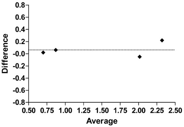
Bland-Altman analysis provides a simple method of plotting the comparison of two methods. The plot in Fig. 3 shows the average of the two measurements (MOSFET and TLD) on the x axis and the difference between the two measurements on the y axis. The bias of nearly zero (0.0625) indicates the comparability of the two methods.
FIG. 3.

Bland-Altman plot for difference between measurements relative to averaged measurements. Dotted line shows this bias (Y = 0.0625).
The focus of this work is for application in low-dose small animal diagnostic imaging where the standard uncertainty is expected to be broader (<8%) than for radiation therapy (1–2%) due to photon statistics. The tissue-equivalent mouse phantom was unique in that the detector placement holes were drilled perpendicular to the long axis of the phantom to avoid any attenuation from the copper MOSFET cables overlapping other dosimeters. Both MOSFETs and TLDs showed an energy dependence, and this has been incorporated in the calibration factors for the respective tube voltages.
As shown in Fig. 2, doses were consistent with material attenuation, with the higher doses at the surface (skin) and lower doses in the phantom (body). Based on the MOSFET results, the dose for the 70 kVp scans was approximately 200% higher in the body and 160% higher at the surface than for the 45 kVp scans. Likewise, higher tube potential resulted in higher dose. At the same tube potential (70 kVp), the dose was 8% higher on the skin than in the body. At the lower energy (45 kVp), the dose was 22% higher on the surface than in the phantom interior. More of the 70 kVp spectra passed through the phantom than was absorbed. The lower energy imparted relatively more dose to the phantom interior than at the higher energy. This is because of the low-energy X-ray absorption in a thin specimen (20 mm in diameter).
The MOSFET dosimeter reported immediate results and the same detector can support multiple exposures with different X-ray techniques (a significant improvement over the hours needed for TLD preparation and reading). MOSFET technology has proven to be a fast, reliable small animal dosimetry method and would be a good system for dose monitoring for serial and gene expression studies.
Acknowledgments
The authors wish to recognize Lauren Daigle for assistance with dosimetry measurements and Cristian T. Badea for work with the micro X-ray system. We would like to thank Richard Youngblood for editorial assistance and Antonia F. Chen for statistical assistance. All work was performed at the Duke Center for In Vivo Microscopy, an NCRR/NCI National Resource (P41 RR005959/U24 CA092656).
References
- 1.Shpilfoygel SD, Close RA, Valentino DJ, Duckwiler GR. X-ray videodensitometric methods for blood flow and velocity measurement: A critical review of literature. Med Phys. 2000;27:2008–2023. doi: 10.1118/1.1288669. [DOI] [PubMed] [Google Scholar]
- 2.Mistretta CA, Ort MG, Cameron JR, Crummy AB, Moran PR. Multiple subtraction technique for enhancing low contrast periodic objects. Invest Radiol. 1973;8:43–49. doi: 10.1097/00004424-197301000-00007. [DOI] [PubMed] [Google Scholar]
- 3.Lin M, Samei E, Badea CT, Yoshizumi TT, Johnson GA. Optimized radiographic spectra for small animal digital subtraction angiography. Med Phys. 2006;33:4249–4257. doi: 10.1118/1.2356646. [DOI] [PubMed] [Google Scholar]
- 4.Rothkamm K, Lobrich M. Evidence for a lack of DNA double-strand break repair in human cell exposed to very low X-ray doses. Proc Natl Acad Sci USA. 2003;100:5057–5062. doi: 10.1073/pnas.0830918100. [DOI] [PMC free article] [PubMed] [Google Scholar]
- 5.Yoo S, Grimm D, Zhu R, Jursinic P, Lopez F, Rownd J, Gillin M. Clinical implementation of AAPM TG61 protocol for kilo-voltage X-ray beam dosimetry. Med Phys. 2002;29:2269–2273. doi: 10.1118/1.1508376. [DOI] [PubMed] [Google Scholar]
- 6.Ma CM, Coffey CW, DeWerd LA, Liu C, Nath R, Seltzer SM, Seuntjens JP. AAPM protocol for 40–300 kV X-ray beam dosimetry in radiotherapy and radiobiology. Med Phys. 2001;28:868–893. doi: 10.1118/1.1374247. [DOI] [PubMed] [Google Scholar]
- 7.Woo MK, Nordal RA. Commissioning and evaluation of a new commercial small rodent X-ray irradiator. Biomed Imaging Interv J. 2006;2:10–14. doi: 10.2349/biij.2.1.e10. [DOI] [PMC free article] [PubMed] [Google Scholar]
- 8.Yoshizumi T, Goodman P, Frush DP, Nguyen G, Toncheva G, Sarder M, Barnes L. Validation of CT organ dose assessment: MOSFET vs. TLD. Am J Roentgenol. 2007;188:1332–1336. doi: 10.2214/AJR.06.0742. [DOI] [PubMed] [Google Scholar]
- 9.Mukundan S, Inman P, Frush DP, Yoshizumi TT, Marcus J, Kloeblen E, Moore M. MOSFET dosimetry for radiation dose assessment of bismuth shielding of the eye in children. Am J Roentgenol. 2007;188:1648–1650. doi: 10.2214/AJR.06.1146. [DOI] [PubMed] [Google Scholar]
- 10.Frush DP, Yoshizumi T. Conventional and CT angiography in children: dosimetry and dose comparisons. Pediatr Radiol. 2006;36:154–158. doi: 10.1007/s00247-006-0190-6. [DOI] [PMC free article] [PubMed] [Google Scholar]
- 11.Lin M, Ning N, Badea CT, Mistry NN, Qi Y, Johnson GA. A high precision contrast injector for small animal X-ray digital subtraction angiography. IEEE Trans Biomed Eng. 2008;55:1082–1091. doi: 10.1109/TBME.2007.909541. [DOI] [PMC free article] [PubMed] [Google Scholar]
- 12.Soubra M, Cygler J, Mackay G. Evaluation of a dual bias metal oxide silicon semiconductor field effect transistor as radiation dosimeter. Med Phys. 1994;21:567–572. doi: 10.1118/1.597314. [DOI] [PubMed] [Google Scholar]
- 13.Hendee WR. Medical Radiation Physics: Roentgenology, Nuclear Medicine & Ultrasound. 2nd. Year Book Medical Publishers; Chicago: 1979. [Google Scholar]
- 14.Hubbell JH, Seltzer SM. Tables of X-Ray Mass Attenuation Coefficients and Mass Energy-Absorption Coefficients from 1 keV to 20 MeV for Elements Z = 1 to 92 and 48 Additional Substances of Dosimetric Interest, Table 4 NISTR 5362. U.S. Department of Commerce; Washington, DC: [April 1, 2008]. Available online at http://physics.nist.gov/PhysRefData/XrayMassCoef/tab4.html. [Google Scholar]
- 15.Cranley K, Gilmore BJ, Fogarty GWA, Desponds L. Catalogue of Diagnostic X-ray Spectra and Other Data. Institute of Physics and Engineering in Medicine; New York: 1997. Report 78. [Google Scholar]


