Abstract
Composite nanostructures (~200 nm wide and several μm long) of metal and polyaniline (PANI) in two new variations of core-shell (PANI-Au) and segmented (Au-PANI and Ni-Au-PANI) architectures were fabricated electrochemically within anodized aluminum oxide (AAO) membranes. Control over the structure of these composites (including the length of the gold shells in the core-shell structures) was accomplished by adjusting the time and rate of electrodeposition, and the pH of the solution from which the materials were grown. Exposure of the core-shell structures to oxygen plasma removed the PANI and yielded aligned gold nanotubes. In the segmented structures, a self-assembled monolayer (SAM) of thioaniline nucleated the growth of PANI on top of metal nanorods, and acted as an adhesion layer between the metal and PANI components.
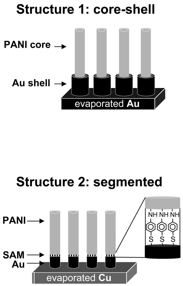
This paper describes the templated synthesis1–9 of two new variations of core-shell6, 10–14 and segmented7–9 composite nanostructures comprising of metal and polyaniline (PANI). To form the core-shell composite (Figure 1, structure 1), we exploited the pH dependence of the chemical structure of PANI, and the solubility of the anodized aluminum oxide (AAO) template in basic solution, to direct the deposition of gold as a shell around a preformed PANI nanotube. The method that we used to fabricate structure 1, unlike the electroless deposition procedure15 used to form gold-coated polypyrrole nanofibers6, or any other published method, produced free-standing composites of PANI nanotubes with gold shells, where both components were of controllable length. To fabricate the segmented composite (Figure 1, structure 2), we formed a self-assembled monolayer (SAM) of thioaniline to nucleate the electropolymerization of aniline on top of a metal nanorod, and create a robust, chemisorbed contact between the metal and the PANI. Films of polypyrrole16 or polyaniline17 that were grown from a metal surface that had been chemically functionalized with the monomer unit have demonstrated greater long-range order and formed stronger, less resistive contacts with metal substrates18, 19 than analogous films grown on bare metal. The electropolymerization from a surface-bound monomer that we employed in the fabrication of structure 2 is the first extension of this strategy to form composite nanostructures.
Figure 1.
Core-shell (1) and segmented (2) polymer-metal nanocomposites.
The desire to create nanostructures that combine the mechanical flexibility, optical properties, and electrical properties of conducting polymers with the high electrical conductivity and magnetic properties of metals has inspired the development of several techniques for the controlled growth of nanocomposites of metals and polymers.6, 7, 20 The utility of polymers as photoactive materials in light-emitting diodes (LEDs) and solar cells18, 21–23, and as substrates for catalysis and for the detection of biologically-active species24, depends largely on i) the directional mobility of charge carriers through the polymer, ii) the amount of surface area that is exposed to light, or is available to form an interface between the polymer and other photoactive materials, biological or chemical species, and iii) the resistance and the surface area of the contacts between the polymer and a metal electrode. Nanotubes are an attractive form of polymers for such purposes because they address issues (i) and (ii): they have a higher ratio of surface area to volume than do spherical nanoparticles, and polymer chains that are aligned within nanotubes provide an anisotropic pathway for electrons.25 The two separate fabrication techniques that we introduce here additionally address the third characteristic of the nanostructure (iii): the geometry and chemical structure of the polymer-metal interface.
As the template for all synthetic procedures, we used an AAO membrane with 200 nm-wide pores. The nanoporous membrane (both AAO and polycarbonate) is the most widely-used sacrificial template for the construction of metal and polymer nanostructures9 (beads26 and nanoporous block co-polymers27 also serve this purpose). The porous membrane permits the synthesis of aligned, electrically-connected arrays of nanocomposites without the need to self-assemble the template (nanoparticles, nanowires, or beads) before deposition of the second material.
Core-Shell Polyaniline-Gold Nanostructures
The core-shell architecture (1) provided a high-surface-area contact between an array of optically- and electrically-active polymer tubes and a metal electrode. In the synthesis of the core-shell structures, by performing a one-step electrodeposition of the gold shell around the polymer tube, and tuning the amount of charge that passed through the electrochemical cell during this deposition, we easily controlled the length of the shell. In contrast, multi-step electroless deposition15 results in a layer of metal over the entire surface of the pores of the membrane.
Scheme 1 outlines the general procedure for the preparation of PANI–Au core-shell nanostructures: We began with an AAO membrane, onto one side of which we evaporated 300 nm of gold using an electron-beam (e-beam) evaporator, and electropolymerized (+0.8 vs. Ag/AgCl, 10 min.) PANI from a solution of aniline in buffer (0.5 M Na2SO4, 0.1 M H2SO4, pH =1) inside the pores of the membrane to yield ~3 μm-long tubes. By tuning the time of electropolymerization, we were able to control the length of the PANI nanotubes generated by the electrodeposition.28 It has been suggested that the PANI grows in tubes, rather than rods, because coupling of oxidized monomers produces cationic short-chain oligomers, which anchor to the negatively charged walls of the membrane.29 Upon drying, ions and solvent exited the polymer, and it contracted.30
Scheme 1.

Procedure for the preparation of the core-shell polymer-metal nanostructures within the pores of a AAO membrane (pore size ~0.2 μm, thickness = 60 μm) backed with 300 nm of Au. The steps are: 1) electropolymerization of PANI at an applied potential of +0.8 vs. Ag/AgCl in buffer solution (0.5 M Na2SO4, 0.1 M H2SO4, pH = 1) (Subsequent drying of the sample causes the polymer nanotubes to shrink inside the pores); 2) electrodeposition of Au from an alkaline gold electroplating solution (pH~10.2) at a current density of 0.5 mA/cm2; 3) complete dissolution of the AAO membrane in 1 M NaOH for 1.5 h.
We then immersed the AAO membrane containing the PANI tubes in a commercially-available gold electroplating solution (pH ~ 10.2) and electrodeposited gold, at a current density of 0.5 mA/cm2, by reduction starting from the gold cathode. The strongly alkaline Au solution simultaneously caused dissolution and widening of the pores of the alumina template, as well as prevented the PANI tubes from re-swelling to the width of the pores.30 An annular space, therefore, formed between the tubes and the membrane. (We discuss these phenomena later). PANI is an insulator at pH 10.2 (σ< 10−10 Ohm−1 m−1)31, so the gold deposited on the gold cathode, and not on the PANI tubes, which acted only as templates for formation of the gold shells. We dissolved the AAO membrane completely by immersing it in 1M NaOH (aq) for 1.5 h.
Figure 2A shows a scanning electron microscopy (SEM) image of the electropolymerized aniline nanofiber, after dissolution of the membrane. Figures 2B–D show SEM images of the polymer-metal core-shell structure we obtained after we electrodeposited Au for 1h (B), 1.5h (C), and 2.5h (D) (with a deposition current of 0.5 mA/cm2) on the preformed PANI nanotubes, and then dissolved the AAO membrane in NaOH. The lengths of the gold shells were approximately 0.5 μm, 1.5 μm, and 3 μm.
Figure 2.
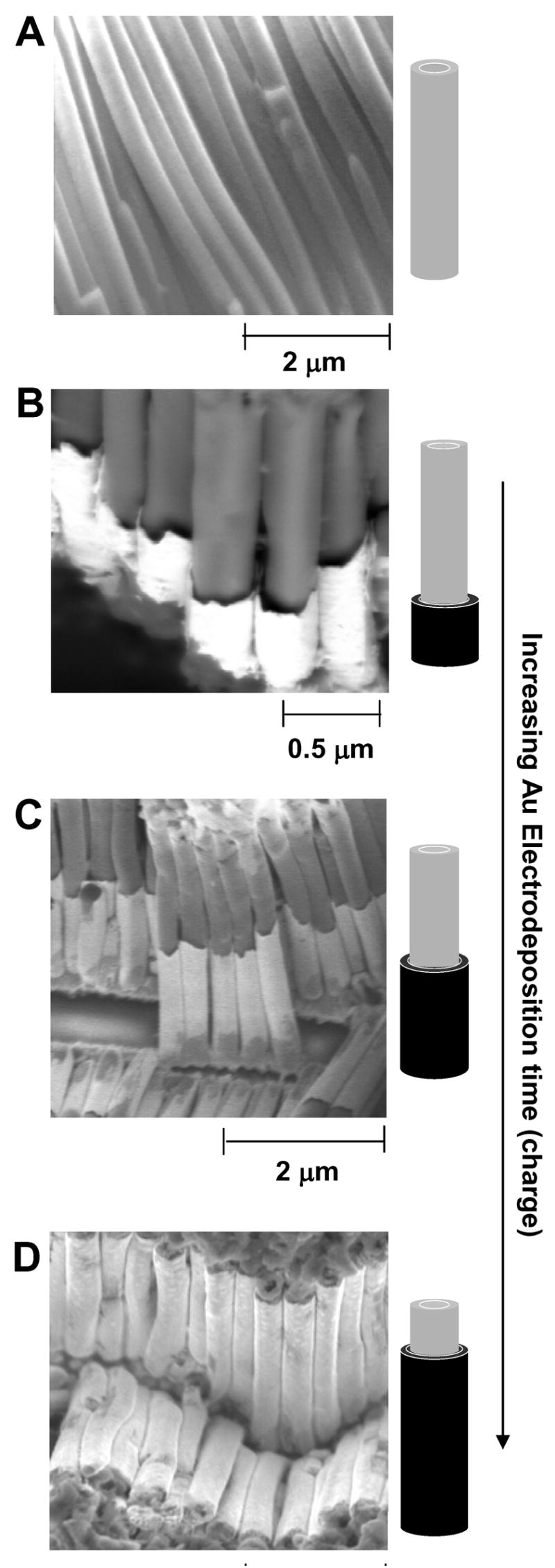
SEM images of nanostructures grown in the AAO membrane (after dissolution of the membrane in 1M NaOH for 1.5 h). A) PANI fiber only; B-D) PANI-Au core-shell structures resulting from the procedure in Scheme 1, where the Au was deposited for 1 h (B), 1.5 h (C) and 2.5 h (D) (see cartoons next to the images).
Mechanism of formation of the core-shell structure
We believe that the annular spaces between the PANI tubes and the walls of the AAO membrane formed for two reasons (although it is difficult to determine their relative contributions to the total mechanism of core-shell formation): i) The AAO membrane dissolves in basic solution. Partial dissolution of the walls of the alumina membrane around the polymer fibers, due to the alkaline medium of the gold electroplating solution, left gaps between the polymer tubes and the walls of the membrane. The gold solution is less basic than the 1 M NaOH (pH ~ 14) used to completely dissolve the membrane, but it easily wet the hydrophilic pores, and probably dissolved the walls homogeneously along the length of the PANI fibers (≤ 3 μm). ii) The counterions that swelled the PANI upon electropolymerization (in the acidic, aqueous monomer solution, PANI exists in its fully protonated, oxidized form), were no longer present when the monomer solution was removed and the polymer was dried. The polymer, therefore, shrunk upon drying. The gold electroplating solution is basic, and did not swell the polymer back to the size of the pores.
When we used different (commercially-available) metal plating solutions with different pH values—Ag (pH 12.5), Ni (pH 5.5), Cu (pH 3.5)—solutions with acidic pH did not lead to the formation of the core-shell structure (we mainly observed free standing polymer fibers with a thin layer of Ni or Cu decorating the top of the fibers). We suspect that, upon adding the acidic Ni and Cu plating solutions, the protonated PANI re-swelled to the size of the un-etched AAO pores, and the Ni and Cu deposited on top of, rather than around, the PANI tubes. When we dissolved the membrane, poor adhesion between the metal and the PANI caused much of the Ni and Cu layers to detach from the PANI. The highly alkaline Ag plating solution caused a fast dissolution of the template, such that the Ag deposited as a film on the gold working electrode covering the base of the tubes, rather than as defined shell structures around the nanotubes.
Plasma Etching of Core-shell Structures to Form Gold Nanotubes
Figures 3 and S1 show the same sample as in Figure 2, but after exposure for 10 min to oxygen plasma (at 1 Torr, 100 W). Plasma oxidation removed the PANI and left the gold shell; this procedure generated an array of aligned, free-standing gold nanotubes. Electron backscattered diffraction (EBSD, Figure S1) identified the bright, fibrous material that emerges from the tubes and is gathered in the bottom-right and top-left corners of the image as gold that originally deposited inside (rather than formed as a shell around) the PANI tubes. We suspect that the gold fibers are very thin because, when the gold deposited inside the tubes, the polymer was in its “shrunken” state.31
Figure 3.
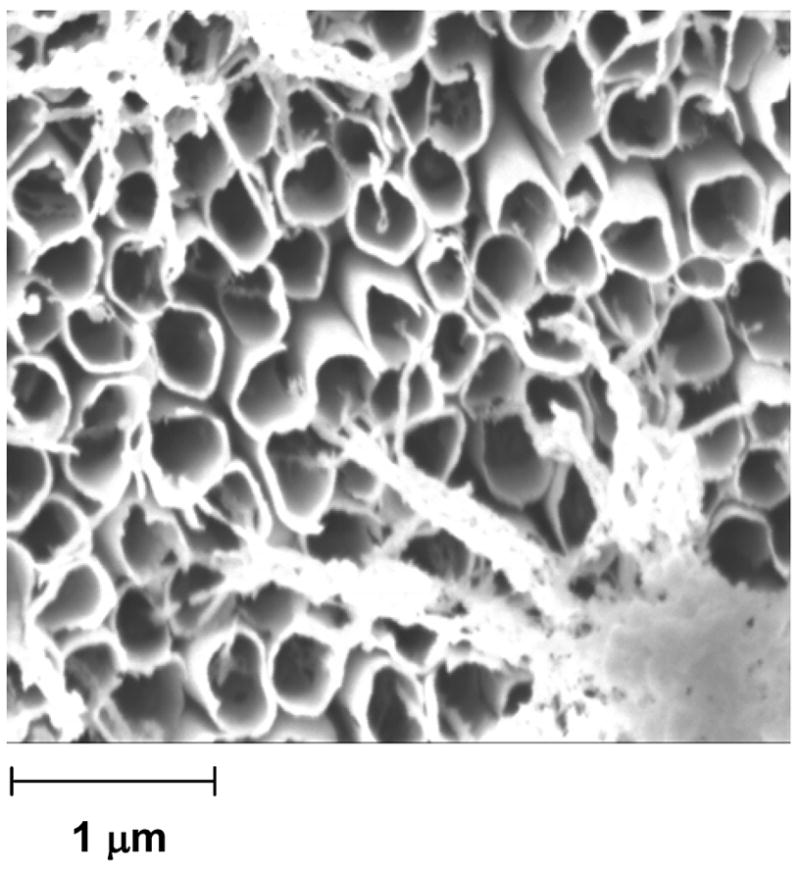
SEM image of Au nanotubes (diameter = ~200 nm) produced when we treated the core-shell structures in Figure 1 with oxygen plasma for 5 min. A small amount of Au deposits inside of the PANI tube during step 2 of Scheme 1. We believe that the fibrous material in the bottom right and top left corners of the imageis Au that had deposited inside of the PANI tubes; this Au was released as the plasma etched the PANI, but remained tethered to the Au backing. Figure S1 shows a larger-area picture of the array of Au nanotubes.
Segmented Polyaniline-Gold Nanofibers
The key feature of our procedure for fabricating segmented metal-PANI composites (structure 2) is the formation of the SAM of thioaniline on top of the gold segment, and the use of the SAM to nucleate the electropolymerization of aniline. The SAM provided a chemisorbed contact between the metal and polymer segments, and added stability to the composite (especially during electrodeposition, when variation in applied potential changes the shape of many electroactive polymers and can delaminate the film).32
Scheme 2 sketches the procedure for fabricating segmented composite metal-PANI nanostructures. We first deposited a 300 nm-thick film of copper (the working electrode) on one face of an AAO membrane using an ebeam evaporator.33 We then electrodeposited metallic Au rods inside the alumina template (current density = 0.5 mA/cm2). A SAM of thioaniline formed on the top surface of the gold rods when we immersed the partially-filled AAO membrane in a 0.01M ethanolic solution of p-mercaptoaniline (HSC6H4NH2) for 1 h. The thioaniline monolayer served as a surface initiation factor to electropolymerize the aniline on top of the gold rods (potentiostatically, at an applied voltage of +0.8 V vs Ag/AgCl for 10 min.). Finally, the AAO membrane dissolved during immersion in 1M NaOH (aq) for 1.5 h.
Scheme 2.
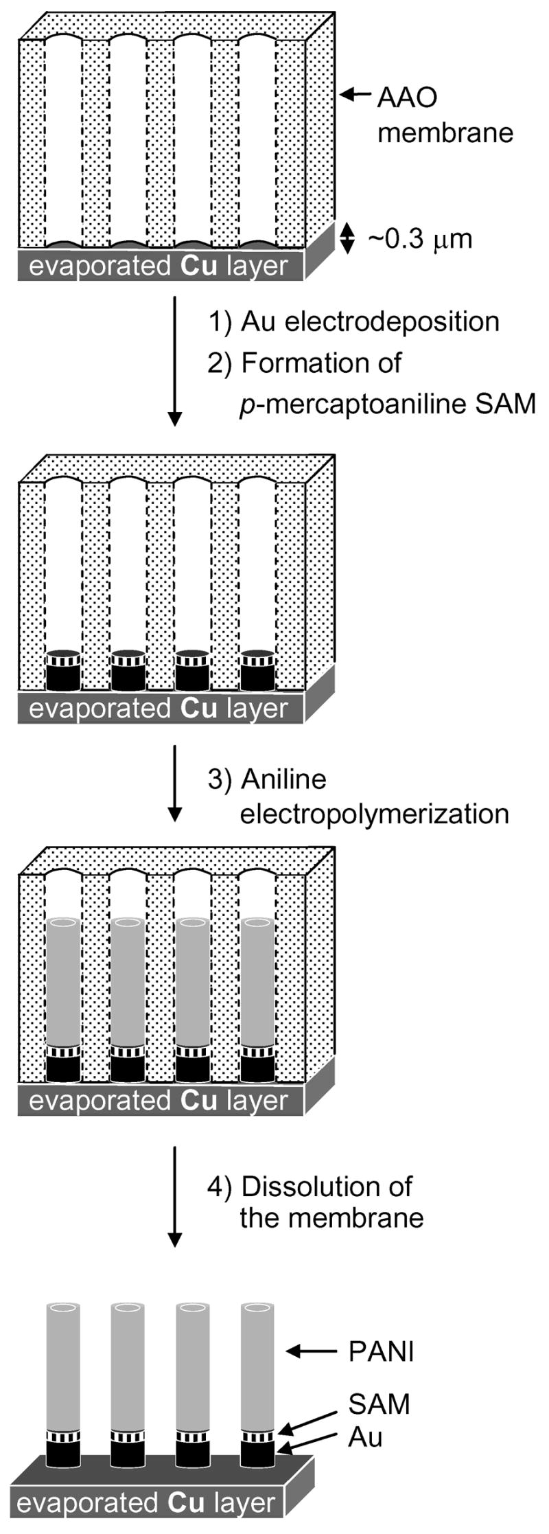
Procedure for the preparation of the segmented polymer-metal nanostructures within the pores of a Cu-backed AAO membrane: 1) electrodeposition of Au from a neutral gold electroplating solution (pH~7.4) at a current density of 0.5 mA/cm2; 2) formation of a SAM of thioaniline (see inset at the bottom of the figure); 3) electropolymerization of PANI; 4) dissolution of the AAO membrane.
We believe that this procedure resulted in chemisorbed contacts between the PANI and the gold rods—that is, crucially, the thioaniline monolayer was stable to an applied potential of +0.8 V under ambient conditions at a pH of ~1. Widrig, et al.34 determined the dependence of the potential for oxidative desorption of n-propanethiolate monolayers from Au surfaces on the pH of a electrolyte (where the electrolyte was a mixture of H3PO4 and KOH at constant ionic strength). For pH≤4, this potential is > 1.2 V vs. Ag/AgCl, and, for pH ~ 1 (the pH of the solution from which the electropolymerization of aniline was carried out), this potential is ~1.4 V.35
Figure 4 shows an SEM image of the nanostructures obtained (after dissolution of the membrane) according to Scheme 2. We clearly obtained structures consisting of two fragments, and there is no detectable space between the metal and the polymer. Figure S2 shows SEM images (cross-section, top, and top view, bottom) of the sample obtained (after dissolution of the membrane) using Scheme S1, where we did not modify the top surface of the gold nanorods with a SAM of thioaniline before the deposition of PANI. We could detect very little PANI on top of the Au rods in this case because, we believe, a failure of adhesion between the polymer and the metal fragment resulted in their detachment once the AAO membrane was dissolved. These results demonstrate the importance of the organic monolayer for the adhesion of the polymer segment to the metal segment.
Figure 4.
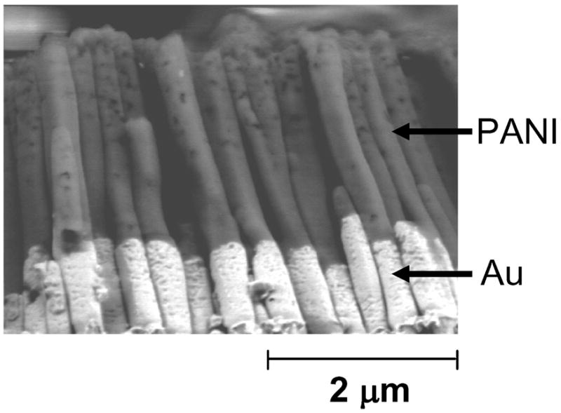
SEM image of Au-PANI segmented nanostructures (that resulted from Scheme 2) subsequent to dissolution of the membrane. The structures pictured here had partially detached from the Cu backing.
Fabrication of Segmented Magnetic Nanostructures
The incorporation of magnetic segments into polyaniline nanostructures introduces a means of potentially controlling their motion and aligning them on a surface in the absence of an electrolyte. Magnetic structures with low densities (formed by complexing magnetic metal with polymer) are also very desirable in biology.11 We prepared nanofibers with segments of PANI, Au and Ni (Figure 5A) using the following procedure: First, we deposited a 300 nm-thick layer of Cu onto one side of the porous AAO membrane. We electrodeposited Ni from a commercially-available solution of nickel sulfamate (pH 5.5) at 0.5 mA/cm2 for 2 h, and Au (pH 7.4) at 0.5 mA/cm2 for 2 h. Immersion of the membrane (with segmented Ni/Au nanorods in the pores) in a 0.1 M ethanolic solution of p-mercaptoaniline for 1 h formed a SAM on the surface of the gold. We electrodeposited the PANI, as previously, for 10 min., and dissolved the membrane by exposing it to 1 M NaOH for 1.5 h.
Figure 5.
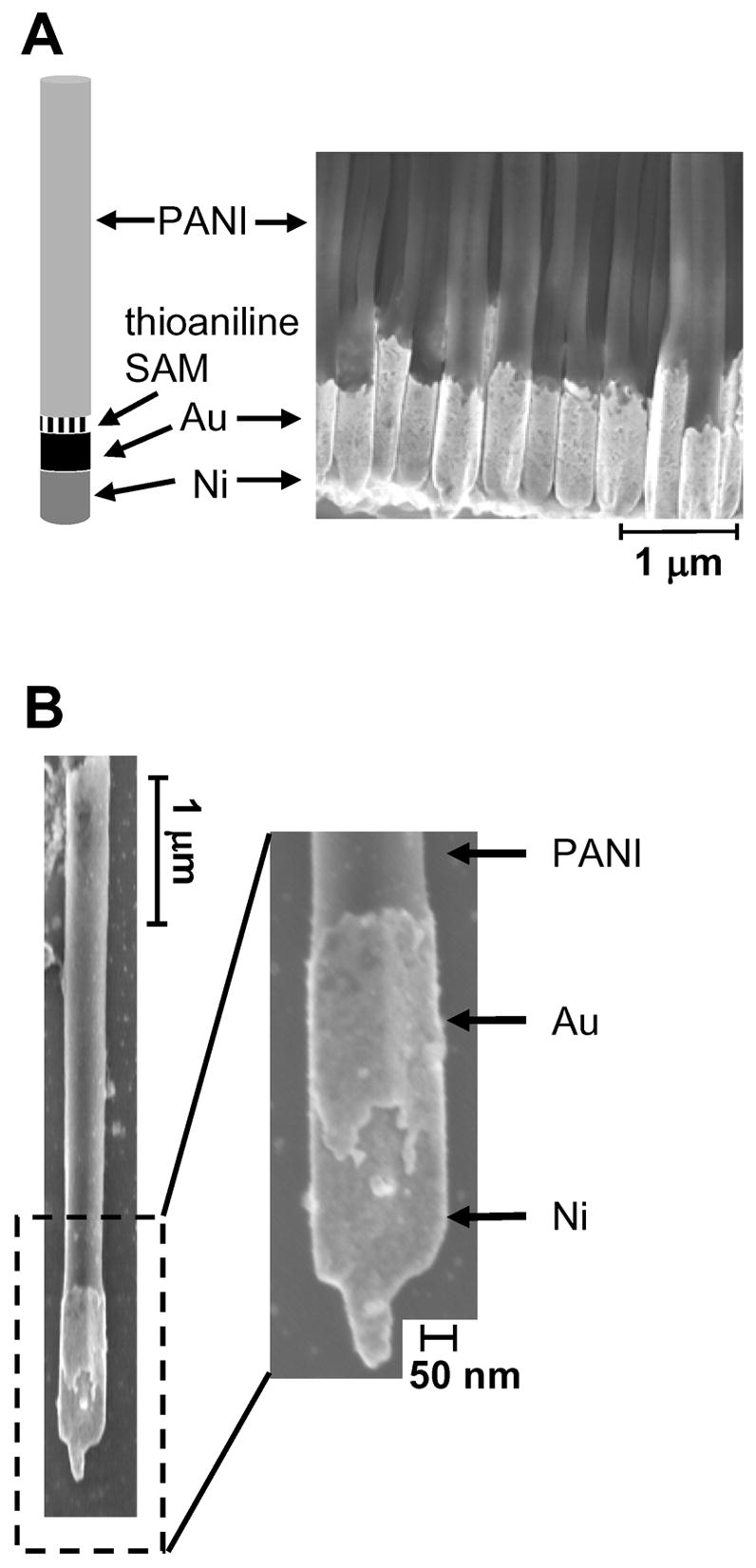
SEM images of the Ni/Au-thioaniline/PANI segmented structure before (A) and after (B) dissolution of the evaporated Cu backing, and, in both cases, after dissolution of the AAO membrane.
Figure 5B shows one of the same nanofibers after dissolution of the evaporated Cu backing (by immersing the sample in 0.3 M aqueous FeCl3 solution for five minutes and washing with water). The nickel layer ends in a fine tip (< 60 nm in diameter). The tips formed because the pores of the membrane were not completely covered by the evaporated Cu backing, and tiny holes remained in the Cu layer. These holes were filled with the first electrodeposited metal, (here, Ni). When we attempted to grow the PANI oxidatively directly on top of the Ni (without intervening layers of Au or thioaniline), the Ni layer dissolved completely, and we saw no nanostructures after dissolution of the AAO membrane. When we deposited a layer of Au before growing the PANI, the Ni segment remained intact through the electropolymerization because the Au separated the Ni segment from the acidic aniline solution, which solvates the Ni cations.
In summary, we have described convenient and adjustable procedures for the preparation of metal-polymer core-shell and segmented nanostructures. The core-shell structures resulted from first growing PANI nanotubes, and subsequently depositing gold from an alkaline plating solution. This solution not only partially dissolved the walls of the membrane, but also prevented the PANI nanotubes from swelling to the size of the pores, so that the gold filled the annular space between the walls of the pores and the PANI, and formed a shell around the PANI nanotube. We believe that this structure is well-suited for incorporation into solar cell and OLED devices, because it allows for deposition of another photoactive material inside the polymer core. We are currently exploring the use of arrays of core-shell polymer-gold nanocomposites as hole-collecting components in a nanostructured, heterojunction solar cell (where the polymer nanotubes are filled with an electron-conducting material). This architecture minimizes the distance both excitons and charges must migrate in order to reach an interface at which they charge separate or inject charge into the circuit, respectively.
Electropolymerization of aniline from a SAM of thioaniline deposited on the surface of the gold nanorods resulted in good adhesion between the metal and PANI components of the segmented structure. Without the SAM, the PANI did not stick to the gold nanorods once the AAO template was dissolved. The formation of a robust, chemisorbed contact between a metal and an organic layer within a nanostructure is a major step in advancing nanofabrication from a collection of techniques that produces images to one that produces functional devices.
Supplementary Material
Experimental procedures, additional SEM images, and a synthetic scheme. This material is available free of charge via the Internet at http://pubs.acs.org.
Acknowledgments
This research was supported by the NIH nanotools (NIH GM065364), the shared Resource facilities supported by the National Science Foundation under NSEC (PHY-0117795) and MRSEC (DMR-0213805), and DARPA under a subaward from the University of Delaware. EAW thanks the Petroleum Research Fund of the American Chemical Society for a fellowship (PRF # 43083-AEF).
References
- 1.Martin CR. Science. 1994;266(5193):1961–1966. doi: 10.1126/science.266.5193.1961. [DOI] [PubMed] [Google Scholar]
- 2.Yoo WC, Lee JK. Adv Mat. 2004;16(13):1097–1101. [Google Scholar]
- 3.Hou S, Harrell CC, Trofin L, Kohli P, Martin CR. J Am Chem Soc. 2004;126:5674–5675. doi: 10.1021/ja049537t. [DOI] [PubMed] [Google Scholar]
- 4.Lahav M, Sehayek T, Vaskevich A, Rubinstein I. Angew Chem Int Ed. 2003;42:5575–5579. doi: 10.1002/anie.200352216. [DOI] [PubMed] [Google Scholar]
- 5.Lu Q, Gao F, Komarneni S, Mallouk TE. J Am Chem Soc. 2004;126:8650–8651. doi: 10.1021/ja0488378. [DOI] [PubMed] [Google Scholar]
- 6.Cepak VM, Hulteen JC, Che G, Jirage KB, Lakshmi BB, Fisher ER, Martin CR. J Mat Res. 1998;13:3070–3080. [Google Scholar]
- 7.Park S, Lim JH, Chung SW, Mirkin C. Science. 2004;303:348–351. doi: 10.1126/science.1093276. [DOI] [PubMed] [Google Scholar]
- 8.Love JC, Urbach AR, Prentiss MG, Whitesides GM. J Am Chem Soc. 2003;125:12696–12697. doi: 10.1021/ja037642h. [DOI] [PubMed] [Google Scholar]
- 9.Martin BR, Dermody DJ, Reiss BD, Fang M, Lyon LA, Natan MJ, Mallouk TE. Adv Mat. 1999;11:1021–1025. [Google Scholar]
- 10.Li L, Yang YW, Li GH, Zhang LD. Small. 2006;2(4):548–553. doi: 10.1002/smll.200500382. [DOI] [PubMed] [Google Scholar]
- 11.Nielsch K, Castano FJ, Matthias S, Lee W, Ross CA. Adv Eng Mat. 2005;7(4):217–221. [Google Scholar]
- 12.Sun Y, Wiley B, Li ZY, Xia Y. J Am Chem Soc. 2004;126:9399–9406. doi: 10.1021/ja048789r. [DOI] [PubMed] [Google Scholar]
- 13.Xu J, Li X, Liu J, Wang X, Peng Q, Li Y. J Poly Sci. 2005;43(Pt A):2892–2900. [Google Scholar]
- 14.Cao H, Tie C, Xu Z. Appl Phys Lett. 2001;78:1592–1594. [Google Scholar]
- 15.Menon VP, Martin CR. Anal Chem. 1995;67:1920–1928. [Google Scholar]
- 16.Sayre C, Collard DM. Langmuir. 1995;11:302–306. [Google Scholar]
- 17.Ulgut B, Zhao Y, Grose JE, Ralph DC, Abruña HD. Langmuir. 2006;22:4433–4437. doi: 10.1021/la053277r. [DOI] [PubMed] [Google Scholar]
- 18.Huang Q, Li J, Evmenenko GA, Dutta P, Marks TJ. Chem Mat. 2006;18:2431–2442. [Google Scholar]
- 19.Ishii H, Sugiyama K, Ito E, Seki K. Adv Mat. 1999;11:605–625. [Google Scholar]
- 20.Bognitzki M, Hou H, Ishaque M, Frese T, Hellwig M, Schwarte C, Schaper A, Wendorff JH, Greiner A. Adv Mat. 2000;12:637–640. [Google Scholar]
- 21.Koller G, Blyth RIR, Sardar SA, Netzer FP, Ramsey MG. Appl Phys Lett. 2000;76:927–929. [Google Scholar]
- 22.Sager BM, Roscheisen MR, Petritsch K, Pichler K, Fidanza J, Yu D. US Pat Appl Publ. 2005. Photovoltaic devices fabricated by growth from porous template. [Google Scholar]
- 23.Paulose M, Shankar K, Varghese OK, Mor GK, Hardin B, Grimes CA. Nanotechnology. 2006;17:1446–1448. [Google Scholar]
- 24.Martin CR, Kohli P. Nature. 2002;2:29–37. doi: 10.1038/nrd988. [DOI] [PubMed] [Google Scholar]
- 25.Wang J, Dai J, Yarlagadda T. Langmuir. 2005;21:9–12. doi: 10.1021/la0475977. [DOI] [PubMed] [Google Scholar]
- 26.Love JC, Gates BD, Wolfe DB, Paul KE, Whitesides GM. Nano Lett. 2002;2:891–894. [Google Scholar]
- 27.Lee JI, Jang JA, Yu JW, Kim JK. Polymer Preprints. 2005;46:549–550. [Google Scholar]
- 28.The electropolymerization requires a gold, rather than silver or copper, working electrode. The highly acidic solution used for polymerization, in combination with the relatively high applied potential, leads to a fast oxidation and dissolution of silver and copper; this dissolution prevents the growth of the polymer fibers.
- 29.Martin CR, Van Dyke LS, Cai Z, Liang W. J Am Chem Soc. 1990;112:8976–8977. [Google Scholar]
- 30.Smela E. Adv Mat. 2003;15:481–494. [Google Scholar]
- 31.Epstein AJ, Ginder JM, Zuo F, Bigelow RW, Woo HS, Tanner DB, Richter AF, Huang WS, MacDiarmid AG. Synth Met. 1987;18:303–309. [Google Scholar]
- 32.Wu CG, Chiang SC, Wu CH. Langmuir. 2002;18:7473–7481. [Google Scholar]
- 33.We chose copper as the backing, rather than the commonly-used silver, because we can dissolve the copper if necessary with 0.3 M aqueous FeCl3, which, unlike the 6 M HNO3 needed to dissolve silver, will not corrode the nickel or degrade the polymer in the nanostructures.
- 34.Widrig CA, Chung C, Porter MD. J Electroanal Chem. 1991;310:335–359. [Google Scholar]
- 35.The mechanism for the oxidative desportion at pH < 4 is believed to be the 3-electron oxidation of RS to RSO2H according to AuSR + 2H20 Au(0) + RS02H + 3e− + 3H+ (see reference 34)
Associated Data
This section collects any data citations, data availability statements, or supplementary materials included in this article.
Supplementary Materials
Experimental procedures, additional SEM images, and a synthetic scheme. This material is available free of charge via the Internet at http://pubs.acs.org.


