

Abstract
Distortion product otoacoustic emission (DPOAE) fine structure has been attributed to the interaction of two cochlear-source mechanisms (distortion and reflection sources). A suppressor presented near the 2f1-f2 frequency reduces the reflection-source contribution and, therefore, DPOAE fine structure. Optimal relationships between stimulus and suppressor conditions, however, have not been described. In this study, the relationship between suppressor level (L3) and stimulus level (L2) was evaluated to determine the L3 that was most effective at reducing fine structure. Subjects were initially screened to find individuals who produced DPOAE fine structure. A difference in the prevalence of fine structure in two frequency intervals was observed. At 2 kHz, 11 of 12 subjects exhibited fine structure, as compared to 5 of 22 subjects at 4 kHz. Only subjects demonstrating fine structure participated in subsequent measurements. DPOAE responses were evaluated in 1/3-octave intervals centered at 2 or 4 kHz, with 4 subjects contributing data at each interval. Multiple L3's were evaluated for each L2, which ranged from 20 to 80 dB SPL. The results indicated that one or more L3's at each L2 were roughly equally effective at reducing DPOAE fine structure. However, no single L3 was effective at all L2's in every subject.
I. INTRODUCTION
There is thought to be more than one mechanism responsible for otoacoustic emission (OAE) generation. These include a coherent-reflection mechanism, a nonlinear-distortion mechanism, or a combination of the two (e.g., Shera and Guinan, 1999; Shera, 2004). Current thinking suggests that, as typically measured in the ear canal, distortion product OAEs (DPOAEs) include contributions from both a distortion source and a reflection source (e.g., Talmadge et al., 1998, 1999; Mauermann et al., 1999; Shera and Guinan, 1999; Stover et al., 1999; Konrad-Martin et al., 2001, 2002). These two sources have phases that rotate with frequency at rates that differ with respect to one another. The phase of the distortion source rotates slowly with frequency, while the phase of the reflection source rotates rapidly with frequency. The difference in rate of phase rotation for the two source mechanisms is believed to explain some of the patterns observed in DPOAE responses (such as fine structure).
When OAEs are recorded in small frequency steps, quasiperiodic patterns of maxima and minima are observed in the response (e.g., Heitmann et al., 1998; Mauermann et al., 1999; Kalluri and Shera, 2001; Goodman et al., 2003). These alternating patterns of maxima and minima are referred to as OAE fine structure or OAE microstructure. In the case of DPOAEs, the fine structure observed in the response is believed to arise from the alternating constructive and destructive interference of the reflection source and the distortion source as a consequence of their different phase-rotation functions. Indeed, it has been shown that DPOAE fine structure is reduced or eliminated if the contribution from the reflection source is reduced or eliminated (Heitmann et al., 1998; Kalluri and Shera, 2001; Konrad-Martin et al., 2001; Mauermann and Kollmeier, 2004).
A number of investigators have speculated that the clinical test performance of DPOAEs is affected by the fine structure present in the response when the contributions from these disparate cochlear sources (and locations) interact (e.g., Heitmann et al., 1998; Shera and Guinan 1999; Shaffer et al., 2003; Mauermann and Kollmeier, 2004; Shera, 2004). According to this argument, the presence of maxima and minima in the DPOAE response may have an unknown influence on the overlap of the distributions of responses from normal and impaired ears. Additionally, because the location of DPOAE maxima and minima can shift in frequency as level is changed (He and Schmiedt, 1993, 1997; Heitmann et al., 1996), the slope of a DPOAE input/output (I/O) function may be affected (Mauermann and Kollmeier, 2004). This could, in theory, affect the accuracy with which DPOAE I/O functions predict behavioral threshold using the approach originally described by Boege and Janssen (2002) and extended by others (e.g., Gorga et al., 2003b; Oswald and Janssen, 2003).
There are two general methods for reducing or eliminating the reflection-source contribution to the DPOAE. One method is a signal-processing approach that involves computing an inverse fast Fourier transform (IFFT) of the DPOAE response and mathematically eliminating the long-latency components thought to arise from the reflection source (Kalluri and Shera, 2001; Knight and Kemp, 2001; Konrad-Martin et al., 2001; Mauermann and Kollmeier, 2004). While this method, often called time windowing, has been shown to be effective at reducing fine structure in DPOAE responses, it requires making DPOAE measurements for many closely spaced frequencies. As a consequence, the windowing approach is time consuming, which makes it inappropriate for many clinical applications.
A second approach, selective suppression, involves presenting a suppressor tone near the 2f1-f2 frequency in order to suppress the reflection-source contribution to the overall DPOAE. The results obtained with selective suppression and time windowing have been shown to be roughly equivalent, although incomplete reduction of fine structure has been observed with selective suppression (Kalluri and Shera, 2001). The selective-suppression approach is particularly well suited for clinical applications because it involves less test time than is needed to implement the windowing approach for removing fine structure. The suppressor tone is presented simultaneously with the two primaries while DPOAE measurements are made in the traditional manner. Unfortunately, the optimal suppressor level for the various stimulus conditions that might be used to make dichotomous decisions or to predict behavioral threshold from a DPOAE I/O function is not known. Several investigators have studied a range of suppressor levels, but have restricted their efforts to a limited range of stimulus levels (e.g., Heitmann et al., 1998; Kalluri and Shera, 2001; Konrad-Martin et al., 2001; Dhar and Shaffer, 2004). A better understanding of the relationship between stimulus and suppressor levels for a wide range of stimulus conditions is needed if the clinical impact of restricting cochlear-source contribution is to be evaluated.
The purpose of the present study was to comprehensively explore, for a range of stimulus levels, suppressor levels that are effective at reducing DPOAE fine structure in subjects with normal hearing. The goal was to identify a set of optimal suppressor conditions which then will be used in a larger study that evaluates the clinical impact of reducing the reflection-source contribution to the DPOAE. Because the contribution of the reflection source is greatest at low stimulus levels and saturates as stimulus level increases (Stover et al., 1996; Konrad-Martin et al., 2001; Mauermann and Kollmeier, 2004), we hypothesized that the optimal suppressor level relative to stimulus level would be higher at low stimulus levels and would grow at a slower rate than stimulus level.
II. METHODS
A. Subjects
Twenty-two subjects with normal hearing were screened for participation in this project. Normal hearing was defined as behavioral thresholds ≤ 10 dB HL (re: ANSI, 1996) for the octave frequencies 0.25 through 8 kHz. Normal 226-Hz tympanograms were required just prior to each session in which DPOAE data were collected. The additional criteria for inclusion in the study are described below. Of the 22 subjects screened, complete data were obtained from 7 subjects. Three ears contributed data to the 2-kHz measures, 3 ears contributed data to the 4-kHz measures, and 1 ear contributed data at both 2 and 4 kHz.
B. Stimuli
All data were collected using custom designed software (EMAV; Neely and Liu, 1993) that controlled a 24-bit soundcard (CardDeluxe, Digital Audio Labs) housed in a PC. This sound card has a full-scale signal-to-noise ratio ≥ 110 dB and crosstalk (at 1 kHz) of −110 dB. With signal levels as high as 80 dB SPL and noise levels between −20 and −25 dB SPL, the measurements reported here were within the dynamic range of the soundcard. The two primary tones (f1 and f2) were generated on separate channels of the soundcard and were mixed acoustically in the ear canal. The suppressor tone (f3) was generated on the same channel as f2. Because f3 and f2 have a larger frequency separation than f3 and f1, generating f3 on the same channel as f2 ensured that intermodulation distortion products arising from the interaction of f3 and f2 did not occur in the same frequency bin as the DPOAE response (2f1-f2).
An ER-10C (Etymotic Research) probe microphone was used to present stimuli and record responses. This system had been modified to remove 20 dB of attenuation from each channel. This modification made it possible to achieve primary and suppressor levels as high as 80 dB SPL in each subject's ear canal.
DPOAE responses were recorded with f2 varying in 1/64-octave steps over 1/3-octave intervals centered at either 2 or 4 kHz. The level of f2 (L2) varied from 20 to 80 dB SPL in 10-dB steps. The level of f1 (L1) and f2/f1 were set according to the following:
These equations have been shown to produce, on average, the largest DPOAE levels in normal-hearing human ears (Johnson et al., 2006).
At each L2, DPOAE responses were obtained for a control condition in which no attempt was made to suppress the reflection-source contribution (i.e., the suppressor was not presented). DPOAE responses were then recorded in the presence of a suppressor tone (f3) whose frequency was 16 Hz below the 2f1-f2 frequency. Presenting a suppressor tone close to the 2f1-f2 frequency reduces or eliminates the contribution of the reflection source to the DPOAE (e.g., Heitmann et al., 1998; Kalluri and Shera, 2001; Konrad-Martin et al., 2001). However, because the level of f3 required to suppress the reflection component across a range of L2 is not known, a variety of suppressor levels (L3) were evaluated.
In all cases, L3 was set according to the following:
Setting L3 according to this equation with C = 20 dB results in at least 15 dB of DPOAE suppression when a suppressor is presented within 100 Hz of f2 (Gorga et al. 2002, 2003a). When L2 = 20 or 30 dB SPL, C values ranged from 0 to 45 dB. For higher L2 levels, C values ranged from 0 to 40 dB, with the constraint that L3 never exceeded 80 dB SPL. In both cases, C was incremented in 5-dB steps. By evaluating this set of L3, we expected to cover conditions ranging from incomplete suppression of the reflection component to over suppression, meaning that the distortion component was also suppressed.
C. Procedures
Prior to data collection, stimuli were calibrated in sound pressure level at the plane of the probe. While concerns have been raised regarding in-the-ear pressure calibration (e.g., Siegel, 1994; Siegel and Hirohata, 1994; Neely and Gorga, 1998), similar concerns exist for other methods of calibrating stimulus level. Many of these concerns are eliminated if stimuli are calibrated in acoustic intensity (Neely and Gorga, 1998). Unfortunately, acoustic-intensity calibration has not been widely used and in-situ pressure calibration is the current standard of practice for DPOAE measures. However, we recognize that this calibration approach may introduce errors for frequencies at and above 4 kHz.
During data collection, measurement-based stopping rules were used such that averaging continued until either the noise floor reached −25 dB SPL or 32-sec of artifact-free averaging had elapsed. Both DPOAE and noise levels were estimated from the 2f1-f2 frequency bin. This was accomplished during data collection by alternately storing 0.25-sec samples of data in one of two buffers. DPOAE level was estimated by summing the contents of the two buffers. Noise level was estimated by subtracting their contents. The use of these stopping rules resulted in noise levels below −20 dB SPL for the majority of subjects and conditions tested.
All data were collected in a sound-treated room. Subjects were seated comfortably in a reclining chair during data collection and either read quietly or slept. Data collection for the 2-kHz conditions took between 7 and 12 2-hour sessions. Data collection for the 4-kHz conditions took between 3 and 7 2-hour sessions. Data-collection time was shorter for the 4-kHz conditions as a result of the lower noise levels in this frequency interval. More averaging was required to produce comparable noise levels for the 2-kHz conditions
D. Analyses
DPOAE amplitude and phase at each point in the fine-structure measure were converted to complex values. Each of these values was then placed in the appropriate frequency position within an 8192-point array of zeroes. An IFFT was computed on the resulting array of real and imaginary numbers. The time window for the analysis is dependent on the step size used to collect the fine-structure measures. The step size for the measurements around 2-kHz was approximately 21 Hz, and a 20-ms window was used for the analysis. The step size for the measurements around 4-kHz was approximately 43 Hz, and a time window of 10 ms was used for the analysis at this frequency. The resulting amplitude values as a function of time were then used to estimate the magnitude of the early (distortion source) and late (reflection source) components in the response. See Konrad-Martin et al. (2001) for additional details regarding this procedure.
In addition to the IFFT analysis, a discrete cosine transform (DCT) (Rao and Yip, 1990) was computed on the DPOAE fine-structure measures. The DCT, which is similar in concept to the FFT, was applied to the log-magnitude (dB) data and had the advantage of closer agreement with visual assessment of fine structure. It provides a quantification of the overall level of the response (the DC component), as well as the levels of higher “frequency” components (measured in cycles/octave) that ride on the DC component. The coefficients of these higher “frequency” components provide a means to quantify the magnitude of the fine structure.
III. RESULTS
A. Fine structure in DPOAE responses
Figure 1 plots an example of fine structure in DPOAE responses for one subject (C110) when measured in a 1/3-octave interval surrounding f2 = 2 kHz. DPOAE responses with L2 ranging from 20 to 80 dB SPL in 10-dB steps are shown with increasing line thickness. Maxima-to-minima depths exceeding 15 to 20 dB are observed for low levels. As has been reported previously (e.g., He and Schmiedt, 1993, 1997; Mauermann and Kollmeier, 2004), the depth of the fine structure decreases as L2 increases, and the frequency at which a given minima occurs shifts with L2. Data from other subjects were similar to those shown in Fig. 1, at least at 2 kHz.
Figure 1.

DPOAE level (dB SPL) as a function of f2 (kHz) for a single subject for the 1/3-octave interval surrounding f2 = 2 kHz. Increasing line thickness indicates increasing L2, which ranged from 20 to 80 dB SPL in 10-dB increments. Each trace has been offset by successive 10-dB increments to aid in visualization.
When screening subjects for participation, DPOAE fine-structure measures were recorded in 1/3-octave intervals surrounding f2 = 2 and/or 4 kHz with L2 = 30 dB SPL. In order to participate, subjects were required to have at least a 10-dB difference between maxima and minima in one cycle of the fine structure within the 1/3-octave interval at this L2. Figure 2 summarizes the prevalence of fine structure in the 2- and 4-kHz intervals. The open bars represent the number of subjects evaluated in each frequency interval and the cross-hatched region indicates the number of subjects meeting the above inclusion criterion. Of 12 subjects screened in the 2-kHz interval, 11 (92%) met the 10-dB maxima-to-minima requirement. In contrast, only 5 of 22 subjects (23%) met the requirement at 4 kHz.
Figure 2.
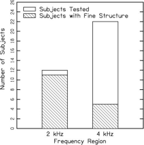
The number of subjects screened in each frequency interval who produced DPOAE fine structure, which was defined as a maxima-to-minima ratio ≥ 10 dB in one cycle of fine structure when L2 = 30 dB SPL. The open bars represent the number of subjects evaluated and the cross-hatched region indicates the number who had DPOAE fine structure.
Each of the 12 people evaluated at 2 kHz were also evaluated at 4 kHz. Data demonstrating the difference in microstructure patterns for these subjects in the intervals around 2 and 4 kHz are shown in Fig. 3. Results for the 2-kHz interval are shown in the 1st and 3rd columns, with results for the 4-kHz interval shown in the 2nd and 4th column. Adjacent panels within a row represent data from the same subject, as indicated by the subject code in the upper right corner of each panel. All DPOAE data shown in this figure are for L2 = 30 dB SPL. At 2 kHz, all but one subject (C106) had fine structure with a maxima-to-minima ratio of 10 dB or greater. In these same subjects, only three (C103, C109, C111) met this definition for the presence of fine structure at 4 kHz.
Figure 3.

DPOAE level (dB SPL) as a function of f2 (kHz) for all subjects screened in both the 2- and 4-kHz intervals. Data for f2 ≈ 2 kHz are shown in the 1st and 3rd columns. Data for f2 ≈ 4 kHz are shown in the 2nd and 4th columns. Adjacent panels within a row represent data from the same subjects, as identified in the upper right corner of each panel. All data in this figure were collected with L2 = 30 dB SPL in the absence of a suppressor tone.
The data shown in Fig. 3 were transformed to the time domain by computing an IFFT of the DPOAE responses. This technique has been used previously (e.g., Kalluri and Shera, 2001; Konrad-Martin et al., 2001, 2002; Mauermann and Kollmeier, 2004) as a method for exploring cochlear-source contribution to the DPOAE recorded in the human ear canal. Figure 4 plots an IFFT of the data shown in Fig. 3, using the same general layout. Columns 1 and 3 represent data for the 2-kHz interval and columns 2 and 4 represent data for the 4-kHz interval. Adjacent panels within a row represent results at 2 and 4 kHz for the same subject. The early components (those occurring near time = 0 ms) are believed to arise from the distortion-source mechanism (near the f2 place), with the later components arising from the reflection-source mechanism (near the 2f1-f2 place).
Figure 4.

Inverse fast Fourier transforms (IFFTs) of the data shown in Fig. 3. The data are plotted as amplitude (relative units) as a function of time (ms). The layout is the same as in Fig. 3. Data for f2 ≈ 2 kHz are shown in the 1st and 3rd columns, f2 ≈ 4 kHz are shown in the 2nd and 4th columns, adjacent panels within a row are for the same subject.
In general, at 4 kHz, the amplitude of the later components (reflection-source components) in Fig. 4 is reduced relative to the amplitude of the early components (distortion-source components) when compared to 2 kHz. This is consistent with the observation in Figs. 2 and 3 that the prevalence of fine structure at 4 kHz is less than the prevalence of fine structure at 2 kHz. Recall that in the case of DPOAEs, fine structure in the response is believed to arise from the constructive and destructive interference of the two source components (e.g., Heitmann et al., 1998; Kalluri and Shera, 2001; Konrad-Martin et al., 2001; Mauerman and Kollmeier, 2004). The reduced amplitude of the reflection-source component at 4 kHz would, therefore, be expected to produce less fine structure at 4 kHz.
B. Effect of a suppressor on DPOAE fine structure in individual ears
Figure 5 shows the effects of a suppressor on DPOAE fine structure in a single subject. The left column plots DPOAE responses for the control condition (no f3) and for several suppressor conditions. The DPOAE levels for the control (no f3) and two suppressor levels are shown in each panel, and suppressor level increases as one moves from the top to bottom panel. The suppression condition is indicated by the value of C used for the given recording. Recall that L3 was set according to L3 = 0.75L2 + C , so that L3 increases as C increases. L2 = 30 dB SPL for all data shown in this figure. As can be seen in the figure, the lowest suppressor levels have little influence on the depth of the fine structure. However, as suppressor level is increased, the difference between maxima and minima decreases. Fine-structure depth reaches a minimum when C is between approximately 20 and 35 dB. Additionally, for these suppressor levels (C = 20 to 35 dB), the overall level of the DPOAE has not been reduced, i.e., the mean DPOAE level across all f2 conditions is relatively constant, despite the apparent reduction in the differences between minima and maxima. Evidence for this conclusion is provided by the constancy (and, therefore, overlap) of the level of the DC component in the top four panels in the left column. This suggests that these suppressor conditions are effective for eliminating the reflection-source component, but do not suppress the distortion-source component. In contrast, the highest suppressor levels (C = 40 or 45 dB) result in a reduction of the overall level of the DPOAE, suggesting that for these conditions the distortion-source component has been suppressed in addition to the reflection-source component.
Figure 5.

Summary of the analyses completed on the data. The data shown in this figure are for a single subject (C110), with L2 = 30 dB SPL, and f2 ≈ 2 kHz. DPOAE responses are shown in the left column along with the DC component (overall DPOAE level) from the discrete cosine transform (DCT) of the data (see text for details regarding the DCT). The level of the higher “frequency” components of the DCT for the same data are shown in the middle column, and an inverse fast Fourier transform (IFFT) of the data in the left column is shown in the right column. In each row, the response in the control condition (no f3) along with results for two suppressor levels (indicated by C value) is shown. Suppressor level increases from top to bottom in the figure.
In order to quantify the magnitude of the overall DPOAE level and the fine structure in control and suppressor conditions, a DCT of the data shown in the left column of Fig. 5 was computed. The DCT provides a way to quantify the overall level of the DPOAE response, which is the DC component shown as the unattached symbols on the far right side of each panel in the left column. The DCT also quantifies the level of the coefficients corresponding to higher frequency constituents of the DPOAE response, which correspond to the fine structure that rides on the overall or DC response in the DPgram. The level of these higher frequency components for each suppressor condition is shown in the middle column in Fig. 5. As expected, the level of these DCT coefficients is greatest where the fine structure is the largest, which occurs in the control condition and/or for the lowest suppressor levels. The level of these DCT coefficients is reduced to a minimum for suppressor conditions corresponding to C = 20 to 35 dB, with little or no reduction in the DC component level (as stated above). Stated another way, these conditions resulted in maximum suppression of fine structure with no effect on overall level. This illustrates how DCT analyses can be used to assess contributions from distortion and reflection sources. Suppressor conditions corresponding to C = 40 and 45 dB are associated with an apparent increase in the higher frequency DCT coefficients, but this is more a consequence of a reduction in the DC level as the DPOAE is suppressed toward the noise floor and fluctuations in the noise exert a larger influence on the measured response. In Fig. 5, the noise floor was typically less than −20 dB SPL.
The data shown as a DPgram in the left column of Fig. 5 are shown as an IFFT in the right column. This analysis provides an alternate means for evaluating the effect of the suppressor on the DPOAE. As expected from the results displayed in the left and middle columns of Fig. 5, the lowest suppressor levels have little effect on either the early or late components in the DPOAE response. Suppressors corresponding to C = 20 to 35 dB have relatively little suppressive effect on the early components of the DPOAE, while suppressing the late components to a level close to the noise floor. Suppressors corresponding to C = 40 and 45 dB have the undesirable effect of suppressing not only the late components (the reflection-source components) but also the early components (the distortion-source components). The similar conclusions drawn from the analyses shown in Fig. 5 suggest that the new DCT analysis can be used to quantify the influence of the suppressor on the fine structure in DPOAE responses.
A summary of the data shown in Fig. 5 (subject C110, L2 = 30 dB SPL and f2 in the interval surrounding 2 kHz) is shown in the left column of Fig. 6. Similar data from a different subject (C117) for the interval surrounding 4 kHz when L2 = 30 dB SPL are shown in the right column. The upper row of Fig. 6 shows the level of the DC component (corresponding to the overall DPOAE level) as a function of suppressor condition, which ranges from the control condition (no suppressor) to the highest suppressor level (L3 = 67.5 dB SPL when L2 = 30 dB SPL and C = 45 dB). The bottom row plots the level of the fine structure relative to the DC component level for each suppressor condition. This measure for the fine structure was obtained by computing the rms level of the coefficients between 1.5 and 22.5 cycles per octave. These components were chosen because pilot data showed them to be the primary components contributing to the fine-structure pattern. The two cases shown in this figure were chosen to demonstrate extreme conditions, one in which it was easy to select an optimal suppressor and one in which the optimal suppressor condition was not obvious.
Figure 6.

The left column plots a summary of the discrete cosine transform (DCT) of the data shown in Fig. 5. The right column plots similar data from a different subject (C117) for the interval surrounding 4 kHz when L2 = 30 dB SPL. The top row plots the DC component level, which corresponds to the overall DPOAE level, as a function of suppressor condition (C). The bottom row represents the rms level of the higher “frequency” components of the DCT (see middle column Fig. 5) and represents the magnitude of the fine structure in the DPOAE response for the various suppressor conditions. See the text for additional information regarding the derivation of these data.
As expected from the data shown in Fig. 5, the data shown in the left column of Fig. 6 indicate that the DC level is relatively constant through approximately C = 35 dB, while the fine structure reaches a minimum at this suppressor level. This suggests that C = 35 dB may be an optimum suppressor condition for this subject and this set of stimulus conditions because it minimizes the fine structure but does not reduce the overall level of the response. The data shown in the right column describe results in which the choice of an optimal suppressor level was more ambiguous. For this subject (C117), the depth of the fine structure is less than was observed for the subject shown in the left column (compare the dBrms level of the fine structure in the control condition for the two subjects). As a result, the effect of the suppressor on the fine structure is less apparent. In the right column, the DC or overall level of the DPOAE is essentially constant for all suppressor levels, with only a small reduction when C = 45 dB. The magnitude of the fine structure reaches a minimum between C = 35 and 45 dB. These data suggest that suppressor levels corresponding to C values between 35 and 45 dB are roughly equivalent and any in this range could be used to reduce fine structure. Additionally, the suppressors had less of an effect in this subject than for the subject whose data are shown in the left column, primarily because this subject (C117) has less fine structure in the control condition. The data from the two subjects in Fig. 6 demonstrate the variability across subjects in terms of the depth of fine structure and the effect of the suppressor on the fine structure.
C. Effect of a suppressor on DPOAE fine structure in a group of subjects
Figure 6 illustrated the effect of a suppressor in two individual ears for a limited set of stimulus conditions. However, the goal of the present study was to identify a set of optimal suppressor conditions across a range of stimulus conditions that could be applied to future studies that evaluate the effect of reducing the reflection-source contribution to the DPOAE in a larger group of subjects. Data addressing this question are shown in Fig. 7.
Figure 7.

Summary of the mean (± 1 standard deviation) discrete cosine transform (DCT) results across the 4 subjects. The left column plots data for the 2-kHz interval, with data for the 4-kHz interval shown in the right column. Data for L2 = 20, 40, 60, and 80 dB SPL are shown, as indicated on the figure. For each L2, the upper panel plots DC level (dB SPL) as a function of suppressor condition and the lower panel plots the rms level (dBrms) of the fine structure. See the text for additional information regarding the derivation of these data.
Figure 7 summarizes the mean DC and fine-structure levels across the four subjects from whom detailed data were collected. Error bars correspond to ± 1 standard deviation. Results for the 2- and 4-kHz intervals are shown in the left and right columns, respectively. Data for L2 = 20, 40, 60, and 80 dB SPL are shown (although not shown, data for intermediate L2 levels were similar). For each L2, two panels are shown. The upper panel corresponds to the DC level and is labeled “dB SPL.” The lower panel in each pair corresponds to the rms level of the fine structure (as described for Fig. 6) and is labeled “dBrms.”
Data such as these could be used to choose suppressor levels for use in evaluating the effect of reducing the reflection-source contribution on DPOAE test performance, including dichotomous decisions about auditory status and predictions of behavioral thresholds. Optimal suppressor level for this purpose is defined as the highest suppressor level at which were was little or no reduction in the DC (overall) level, but there was a corresponding minimum in the rms level of the fine structure. According to this definition of optimal suppressor level, when f2 = 4 kHz and L2 = 40 dB SPL, a suppressor corresponding to C = 30 dB would be identified as optimal. In general, for both the 2- and 4-kHz intervals, the optimal suppressor level ( L3 = 0.75L2 + C ) decreases as L2 increases. This approach to identifying optimal suppressor levels for use in future studies has the advantage of demonstrating the effect the suppressor had on the DC and rms levels of the response. It does not, however, provide information regarding how much the optimal suppressor level varied across the individual subjects. For example, it blurs the differences in patterns of response across subjects, such as those shown in Fig. 6.
Figure 8 describes intersubject variability in optimal-suppressor condition as well as the relationship between optimal-suppressor level and stimulus level. Instead of using data plotted in the form shown in Figs. 6 and 7, these plots could be used as an alternate method for identifying optimal suppressor levels for future use. In this figure, the optimal suppressor (as defined above) is plotted for each subject as a function of L2. Data for f2 ≈ 2 kHz are shown in the left column, with data corresponding to f2 ≈ 4 kHz shown in the right column. The top row plots C value as a function of L2, the middle row plots suppressor level ( L3 = 0.75L2 + C ) as a function of L2, and the bottom row plots suppressor level relative to L2. The sloping lines represent linear fits to these data, with the fits shown as insets in each panel. The r2 values associated with these fits are also shown in each panel. The circles filled with asterisks in the right column indicate results for an individual subject.
Figure 8.

. The relationship between suppressor level and L2 in individual subjects. Data for the 2-kHz interval are shown in the left column and data for the 4-kHz interval are shown in the right column. Each row represents an alternate view of suppressor level (L3). The top row plots C ( L3 = 0.75L2 + C ) as a function of L2. The middle row plots absolute suppressor level (dB SPL) as a function of L2, with the bottom row plotting suppressor level re: L2 as a function of L2. The solid slanting lines represent linear fits to these data; the fits are shown as insets in each panel. The r2 values associated with these fits are also shown in each panel. The circles filled with asterisks in the right column highlight data from an individual subject, as indicated in the text.
Consistent with the data shown in Fig. 7, the optimal value of C (upper panel) decreases with L2 and optimal suppressor level (middle panel) grows at a rate slower than L2 such that the optimal suppressor is much higher than L2 for low L2 levels and is nearly equal to L2 for high levels (bottom panel). Although there is variability across subjects in the optimal suppressor levels, most subjects showed the same general trend of decreasing suppressor level relative to L2 as L2 increased. The optimal-suppressor levels across subjects were typically within 10 to 15 dB. An exception to this is the subject whose data are highlighted (circles filled with asterisks) in the right column of Fig. 8. This subject typically required suppressor levels lower than the other subjects and did not show a consistent pattern of decreasing C value as L2 increased.
The r2 values associated with the linear fits to these data indicate that between 35 and 89% of the variance is accounted for, with higher r2 values at 2 kHz as compared to 4 kHz. While these r2 values indicate reasonable fits to the data, the variability in optimal suppressor level across individual subjects suggests that it may be difficult to choose a single suppressor level that is optimal across all subjects. Even after excluding the data from the subject whose response patterns differed from the pattern seen in other subjects, the optimal suppressor levels covered a 10- to 15-dB range at nearly every L2 (the exception being the suppressor level when f2 ≈ 2 kHz and L2 = 40 dB SPL).
IV. DISCUSSION
The results described above summarize an exploration of the suppressor level that is effective at reducing fine structure in DPOAE responses for a range of stimulus levels. As reported by others, these results suggest that it is possible to reduce or eliminate fine structure in DPOAE responses by playing a suppressor tone close to 2f1-f2. A general trend was observed, such that the suppressor level (relative to stimulus level) needed to eliminate fine structure decreases as stimulus level increases. There is, however, variability across subjects in the suppressor level that is most effective at reducing fine structure. Additionally, the prevalence of fine structure was frequency dependent, occurring more frequently around 2 kHz, as compared to 4 kHz.
A. Differences in fine structure across frequency
The mechanism responsible for the relative lack of fine structure at 4 kHz as compared to 2 kHz is unclear, although this observation has been reported previously. Dhar and Shaffer (2004) observed that, in a group of 20 subjects, 60% showed little or no fine structure above 3 kHz. This percentage is slightly lower than observed for the present study where 77% of subjects evaluated at 4 kHz failed to meet our inclusion criteria for depth of fine structure.
The data shown in Fig. 4 indicate that there is a relatively smaller contribution to the DPOAE from later (reflection-source) components at 4 kHz as compared to 2 kHz, which, in turn, would be expected to produce less fine structure at 4 kHz as compared to 2 kHz. A similar observation was reported in a more quantitative fashion by Konrad-Martin et al. (2001). Although the measurement paradigm used by Konrad-Martin et al. was different than the present study (Konrad-Martin et al. used a fixed f2 paradigm), they conducted a similar IFFT analysis and quantified the magnitude of the early and late components in the response. The magnitude of the early components, which are believed to correspond to the distortion-source components, was greater than the magnitude of the late components, which are believed to correspond to the reflection-source components.
Even if the above observation regarding the relative magnitude of early and late components is correct, an explanation for why the reflection source might contribute less to the DPOAE at 4 kHz as compared to 2 kHz is lacking. The modeling work of Talmadge et al. (1998) suggests that reflections within the cochlea at the stapes footplate (termed basal reflectance in the model) play a primary role in producing the fine structure observed in OAE responses, including DPOAEs. The magnitude of the basal reflectance varies with frequency and could potentially play a role in producing differences across frequency. In addition to basal reflectance, the Talmadge et al. model suggests two other terms that play a role in producing DPOAE fine structure. These include apical reflectance, which essentially corresponds to the reflection source, and the wave-number ratio. The latter term does not have a simple physical interpretation. However, if the Talmadge et al. model is correct, the basal-reflectance term and the wave-number-ratio term have phases that vary slowly with respect to one another. In certain frequency regions, they would be expected to cancel out, with the result being reduced or absent fine structure in that frequency region. It is unclear whether this prediction of the model is correct, but it is consistent with the observation of limited fine structure in the vicinity of 4 kHz in present study and the Dhar and Shaffer (2004) results.
It is also possible that our choice of stimulus parameters played a role in the relative lack of fine structure at 4 kHz. Konrad-Martin et al. (2001) showed that changes in stimulus parameters could affect the relative energy of early and late components in the DPOAE response. When DPOAE responses were recorded using the L1, L2 relationship recommended by Kummer et al. (1998), which was thought to optimize DPOAE level (as compared to a constant 10-dB difference between L1 and L2), Konrad-Martin et al. showed that the late components remained essentially constant in level while the early components increased in level. The stimulus parameters in the present study produce larger DPOAE levels in normal-hearing subjects (Neely et al., 2005; Johnson et al., 2006) than those recorded using the stimulus parameters described by Kummer et al. (1998). It is possible that our stimulus parameters, helped to reduce fine structure by increasing the level of the early components relative to the level of the later components. This hypothesis, however, was not tested. Additionally, it is unclear why changing stimulus parameters would have a differential effect on fine structure at 4 kHz as compared to 2 kHz, particularly since the two regions are close together in relation to the entire length of the basilar membrane.
B. Suppressor levels relative to L2
Consistent with our hypotheses at the outset, the data shown in Figs. 7 and 8 suggest that for low L2 levels, the suppressor needs to be much higher than L2 in order to reduce DPOAE fine structure. However, the optimal suppressor level increases at a slower rate than L2 so that when L2 = 80 dB SPL, suppressors equal to or less than L2 result in maximum suppression of fine structure with little or no effect on overall DPOAE level. This trend of higher suppressor levels (re: L2) for low L2 levels as compared to high L2 levels is consistent with expected differences in the relative contributions from reflection and distortion sources as level is increased. The results from a number of investigators (e.g., Stover et al., 1996; Konrad-Martin et al., 2001; Mauermann and Kollmeier, 2004) suggest that the reflection-source contribution, relative to the contribution from the distortion source, is larger at low stimulus levels and saturates as level is increased, such that the contribution from the reflection source is reduced for high stimulus levels.
C. Suppressing DPOAE Fine Structure and Clinical Test Performance
A number of investigators have speculated that the multiple sources contributing to DPOAEs and the resulting fine structure may have a negative impact on the clinical test performance of DPOAEs (e.g., Heitmann et al., 1998; Shera and Guinan 1999; Shaffer et al., 2003; Mauermann and Kollmeier, 2004; Shera, 2004). However, no data have been reported that directly test this hypothesis. Dhar and Shaffer (2004) reported a general lack of statistically significant correlations between DPOAE level (for moderate-level stimuli) and behavioral threshold in a small group of normal-hearing subjects, even when the reflection source was eliminated. Although the Dhar and Shaffer data cast doubt on the view that controlling source contribution will improve DPOAE test performance, additional work with a larger group of subjects with both normal and impaired hearing is needed. However, before such studies can be completed, the relationship between stimulus level and optimal suppressor level needs to be understood. The data from the present study demonstrate that it is possible to reduce or eliminate fine structure from DPOAE measurements without also affecting overall DPOAE level. In general, the trend of decreasing optimal suppressor level (re: L2) as L2 increased was consistent across subjects. Although there was variability in the optimal suppressor level across subjects (typically with a range of 10 to 15 dB at each L2), for many subjects, several suppressor levels were nearly equivalent in their ability to reduce fine structure (see, for example, Figs. 5 and 6). Although this result is encouraging, one subject (see highlighted points at 4 kHz in Fig. 8) responded differently to the suppressor tone than the other subjects. In this subject, lower and more variable suppressor levels were deemed optimal. Presenting higher level suppressors in this subject's ear typically resulted in reduction in the overall level of the DPOAE. If a large number of ears react in this manner, then it might actually be the case that test performance will be poorer if one attempted to suppress the reflection source. Furthermore, the data shown in Figs. 2, 3, and 4 call into question the extent to which uncontrolled source contribution limits test performance when f2 ≈ 4 kHz. For this frequency interval, fine structure was not present in the majority of ears and, when it was present, the reflection-source contribution was reduced compared to the 2-kHz interval. This latter observation suggests that even if fine structure was present, its impact would be minimal, especially for stimulus levels in routine clinical use.
In summary, by evaluating a range of suppressor levels, it was possible to reduce fine structure in DPOAE responses. The time involved in collecting data such as those in the present study, however, make it impossible to identify an optimal suppressor level for each individual ear under clinical conditions. Under clinical conditions, it is necessary to have a priori knowledge of the optimal suppressor level for a given stimulus condition. The data shown in Fig. 7 or the linear equations shown in Fig. 8 could be used to choose suppressor conditions when evaluating DPOAE test performance when the reflection-source contribution is reduced or eliminated. Although similar trends were observed across most subjects, the intersubject variability in optimal suppressor level suggests that a single suppressor level may not be appropriate in all cases.
ACKNOWLEDGMENTS
Work supported by the NIH NIDCD F32-DC007536, R01-DC02251, P30-DC04662. The authors would like to thank Darcia Dierking and Cassie Garner for their assistance with data collection. Helpful comments from John Rosowski and an anonymous reviewer on an previous version of the manuscript are also gratefully acknowledged.
Footnotes
Portions of this work were presented at the 29th Midwinter Meeting of the Association for Research in Otolaryngology, Baltimore, MD, February 2006.
REFERENCES
- ANSI . Specifications for audiometers. American National Standards Institute; New York: 1996. ANSI 3.6−1996. [Google Scholar]
- Boege P, Janssen T. Pure-tone threshold estimation from extrapolated distortion product otoacoustic emission I/O-functions in normal and cochlear hearing loss ears. J. Acoust. Soc. Am. 2002;111:1810–1818. doi: 10.1121/1.1460923. [DOI] [PubMed] [Google Scholar]
- Dhar S, Shaffer LA. Effects of a suppressor tone on distortion-product otoacoustic emissions fine structure: Why a universal suppressor level is not a practical solution to obtaining single-generator DP-Grams. Ear Hear. 2004;25:573–585. doi: 10.1097/00003446-200412000-00006. [DOI] [PubMed] [Google Scholar]
- Goodman SS, Withnell RH, Shera CA. The origin of SFOAE microstructure in the guinea pig. Hear. Res. 2003;183:7–17. doi: 10.1016/s0378-5955(03)00193-x. [DOI] [PubMed] [Google Scholar]
- Gorga MP, Neely ST, Dierking DM, Dorn PA, Hoover BM, Fitzpatrick DF. Distortion product otoacoustic emission suppression tuning curves in normal-hearing and hearing-impaired human ears. J. Acoust. Soc. Am. 2003a;114:263–278. doi: 10.1121/1.1575751. [DOI] [PubMed] [Google Scholar]
- Gorga MP, Neely ST, Dorn PA, Hoover BM. Further efforts to predict pure-tone thresholds from distortion product otoacoustic emission input/output functions. J. Acoust. Soc. Am. 2003b;113:3275–3284. doi: 10.1121/1.1570433. [DOI] [PubMed] [Google Scholar]
- Gorga MP, Neely ST, Dorn PA, Konrad-Martin D. The use of distortion product otoacoustic emission suppression as an estimate of response growth. J. Acoust. Soc. Am. 2002;111:271–284. doi: 10.1121/1.1426372. [DOI] [PubMed] [Google Scholar]
- He N-j., Schmiedt RA. Fine structure of the 2f1-f2 acoustic distortion product: Changes with primary level. J. Acoust. Soc. Am. 1993;94:2659–2669. doi: 10.1121/1.407350. [DOI] [PubMed] [Google Scholar]
- He N-j., Schmiedt RA. Fine structure of the 2f1-f2 acoustic distortion products: Effects of primary level and frequency ratios. J. Acoust. Soc. Am. 1997;101:3554–3565. doi: 10.1121/1.418316. [DOI] [PubMed] [Google Scholar]
- Heitmann J, Waldmann B, Plinkert PK. Limitations in the use of distortion product otoacoustic emissions in objective audiometry as the result of fine structure. J. Acoust. Soc. Am. 1996;253:167–171. doi: 10.1007/BF00615115. [DOI] [PubMed] [Google Scholar]
- Heitmann J, Waldmann B, Schnitzler H-U, Plinkert PK, Zenner H-P. Suppression of distortion product otoacoustic emissions (DPOAE) near 2f1-f2 removes DP-gram fine structure – Evidence for a secondary generator. J. Acoust. Soc. Am. 1998;103:1527–1531. [Google Scholar]
- Johnson TA, Neely ST, Garner CA, Gorga MP. Influence of primary-level and primary-frequency ratio on human distortion product otoacoustic emissions. J. Acoust. Soc. Am. 2006;119:418–428. doi: 10.1121/1.2133714. [DOI] [PMC free article] [PubMed] [Google Scholar]
- Kalluri R, Shera CA. Distortion-product source unmixing: A test of the two-mechanism model for DPOAE generation. J. Acoust. Soc. Am. 2001;109:622–637. doi: 10.1121/1.1334597. [DOI] [PubMed] [Google Scholar]
- Knight RD, Kemp DT. Wave and place fixed DPOAE maps of the human ear. J. Acoust. Soc. Am. 2001;109:1513–1525. doi: 10.1121/1.1354197. [DOI] [PubMed] [Google Scholar]
- Konrad-Martin D, Neely ST, Keefe DH, Dorn PA, Gorga MP. Sources of distortion product otoacoustic emissions revealed by suppression experiments and inverse fast Fourier transforms in normal ears. J. Acoust. Soc. Am. 2001;109:2862–2879. doi: 10.1121/1.1370356. [DOI] [PubMed] [Google Scholar]
- Konrad-Martin D, Neely ST, Keefe DH, Dorn PA, Cyr E, Gorga MP. Sources of DPOAEs revealed by suppression experiments, inverse fast Fourier transforms, and SFOAEs in impaired ears. J. Acoust. Soc. Am. 2002;111:1800–1809. doi: 10.1121/1.1455024. [DOI] [PubMed] [Google Scholar]
- Kummer P, Janssen T, Arnold W. The level and growth behavior of the 2f1-f2 distortion product otoacoustic emission and its relationship to auditory sensitivity in normal hearing and cochlear hearing loss. J. Acoust. Soc. Am. 1998;103:3431–3444. doi: 10.1121/1.423054. [DOI] [PubMed] [Google Scholar]
- Mauermann M, Kollmeier B. Distortion product otoacoustic emission (DPOAE) input/output functions and the influence of the second DPOAE source. J. Acoust. Soc. Am. 2004;116:2199–2212. doi: 10.1121/1.1791719. [DOI] [PubMed] [Google Scholar]
- Mauermann M, Uppenkamp S, van Hengel PWJ, Kollmeier B. Evidence for the distortion product frequency place as a source of distortion product otoacoustic emission (DPOAE) fine structure in humans. I. Fine structure and higher-order DPOAE as a function of the frequency ratio f2/f1. J. Acoust. Soc. Am. 1999;106:3473–3483. doi: 10.1121/1.428200. [DOI] [PubMed] [Google Scholar]
- Neely ST, Gorga MP. Comparison between intensity and pressure as measures of sound level in the ear canal. J. Acoust. Soc. Am. 1998;104:2925–2934. doi: 10.1121/1.423876. [DOI] [PubMed] [Google Scholar]
- Neely ST, Liu Z. Tech. Memo. Vol. 17. Boys Town National Research Hospital; Omaha, NE: 1993. EMAV: Otoacoustic emission averager. [Google Scholar]
- Neely ST, Johnson TA, Gorga MP. Distortion-product otoacoustic emission measured with continuously varying stimulus level. J. Acoust. Soc. Am. 2005;117:1248–1259. doi: 10.1121/1.1853253. [DOI] [PMC free article] [PubMed] [Google Scholar]
- Oswald JA, Janssen T. Weighted DPOAE input/output functions: A tool for automatic assessment of hearing loss in clinical application. Z. Med. Phys. 2003;13:93–98. doi: 10.1078/0939-3889-00148. [DOI] [PubMed] [Google Scholar]
- Rao KR, Yip P. Discrete cosine transform: Algorithms, advantages, applications. Academic Press; Boston: 1990. [Google Scholar]
- Shaffer LA, Withnell RH, Dhar S, Lilly DJ, Goodman SS, Harmon KM. Sources and mechanisms of DPOAE generation: Implications for the prediction of auditory sensitivity. Ear Hear. 2003;24:367–379. doi: 10.1097/01.AUD.0000090439.16438.9F. [DOI] [PubMed] [Google Scholar]
- Shera CA. Mechanisms of mammalian otoacoustic emission and their implications for the clinical utility of otoacoustic emissions. Ear Hear. 2004;25:86–97. doi: 10.1097/01.aud.0000121200.90211.83. [DOI] [PubMed] [Google Scholar]
- Shera CA, Guinan JJ., Jr. Evoked otoacoustic emissions arise by two fundamentally different mechanisms: a taxonomy for mammalian OAEs. J. Acoust. Soc. Am. 1999;105:782–798. doi: 10.1121/1.426948. [DOI] [PubMed] [Google Scholar]
- Siegel JH. Ear-canal standing waves and high-frequency sound calibration using otoacoustic emission probes. J. Acoust. Soc. Am. 1994;95:2589–2597. [Google Scholar]
- Siegel JH, Hirohata ET. Sound calibration and distortion product otoacoustic emissions at high frequencies. Hear. Res. 1994;80:146–152. doi: 10.1016/0378-5955(94)90106-6. [DOI] [PubMed] [Google Scholar]
- Stover LJ, Neely ST, Gorga MP. Latency and multiple sources of distortion product otoacoustic emissions. J. Acoust. Soc. Am. 1996;99:1016–1024. doi: 10.1121/1.414630. [DOI] [PubMed] [Google Scholar]
- Stover LJ, Neely ST, Gorga MP. Cochlear generation of intermodulation distortion revealed by DPOAE frequency functions in normal and impaired ears. J. Acoust. Soc. Am. 1999;106:2669–2678. doi: 10.1121/1.428097. [DOI] [PubMed] [Google Scholar]
- Talmadge CL, Long GR, Tubis A, Dhar S. Experimental confirmation of the two-source interference model for the fine structure of distortion product otoacoustic emissions. J. Acoust. Soc. Am. 1999;105:275–292. doi: 10.1121/1.424584. [DOI] [PubMed] [Google Scholar]
- Talmadge CL, Tubis A, Long GR, Piskorski P. Modeling otoacoustic emission and hearing threshold fine structures. J. Acoust. Soc. Am. 1998;104:1517–1543. doi: 10.1121/1.424364. [DOI] [PubMed] [Google Scholar]