Abstract
Peptides or proteins near surfaces exhibit different structural properties from those present in a homogenous solution, and these differences give rise to varied biological activity. Therefore, understanding the detailed molecular structure of these molecules tethered to a surface is important for interpreting the performance of the various microarrays based on the activities of the immobilized peptides or proteins. We performed molecular dynamics simulations of a pentapeptide, RHSVV, an epitope of the tumor suppressor protein p53, tethered via a spacer on a functionalized silica surface and free in solution, to study their structural and conformational differences. These calculations allowed analyses of the peptide-surface interactions, the sequence-orientations and the translational motions of the peptide on surface to be performed. Conformational similarities are found among dominant structures of the tethered and free peptide. In the peptide microarray simulations, the peptide fluctuates between a parallel and tilted orientation driven in part by the hydrophobic interactions between the nonpolar peptide residues and the methyl-terminated silica surface. The perpendicular movement of the peptide relative to the surface is also restricted due to the hydrophobic nature of the microarray surface. With regard to structures available for recognition and binding, we find that similar conformations to those found in solution are available to the peptide tethered to the surface, but with a shifted equilibrium constant. Comparisons with experimental results show important implications of this for peptide microarray design and assays.
Introduction
Protein/peptide microarrays, which enable high throughput, parallel analysis of proteins of interest, provide a powerful and sensitive tool for drug discovery and clinical diagnostics 1–4. In a typical design for a protein microarray, the protein or peptide probes (the capture agents) are covalently tethered or noncovalently adsorbed onto the chip surface 5,6. Significant conformational changes may occur when the proteins or peptides encounter the surface 7,8 including complete denaturation and eventual fouling of the surface 9. Because of the potential folding instability of proteins, the appropriate choice of the support surface and choice of immobilization strategy remain technical obstacles 10 in the development of some applications for protein microarrays. Despite numerous efforts comparing and evaluating biochip surface coatings 11–14 and immobilization methods 15–19 with respect to the performance of protein microarrays, there exists no universal solution to maintaining the full biological activity of any protein upon surface immobilization. The success in control and manipulation of the protein functionality in the microarray context requires a detailed knowledge of the molecular structure of the protein immobilized on the microarray chip and the protein-surface interactions.
A number of recent studies of protein/peptide adsorption to solid surfaces are of relevance here 20–27. A spectroscopic study of the adsorption of an α-helical peptide to silica substrates revealed the conformational changes induced by the peptide-surface electrostatic interaction and orientational specificity based on patterned charge complementarities 22. Colloid (meso) scale modeling of antibodies adsorbed on the charged surfaces identified the systematic effects of the surface charge sign and density, solution pH and ionic strength on the orientation of antibodies 23. The free energy of adsorption has been approximated theoretically for individual charged peptide residues on the self-assembled monolayer (SAM) surfaces with varying surface functional groups 24. Of considerable relevance to the present study, a molecular dynamics simulation of the adsorption behavior of a protein fragment suggested the possibility of controlling the orientation of adsorbed proteins by manipulation of surface functionality 27. However, those studies only characterized the non-specific, physical adsorption of proteins/peptides to the surface.
For target molecules to effectively interact with the surface capture peptides, the peptides should adopt a favorable conformation to allow optimal accessibility. Microarray experiments have shown that specifically oriented probes outperform randomly immobilized ones in the peptide aptamer assay 28, antibody capture assay 15,18 and enzymatic activity assay 29. The addition of a spacer which potentially increases the distance between the tethered peptide/protein and surface, can increase the access of the capture agent to the target protein in the solution phase, improving the performance of binding in “affibody” capture arrays 17. However, since the molecular details of proteins immobilized on surfaces is still largely unknown, difficulties in determining the underlying physical/chemical reasons for variations in microarray performance have remained.
Both experimental and theoretical work has begun to address characterizing the effect of surface tethering on proteins. Single-molecule fluorescence resonance energy transfer (FRET) has been utilized to capture the structure and folding dynamics of the proteins immobilized on surfaces 30,31. Coarse-grained 32–34 molecular simulation studies suggest a profound impact of model surfaces on the thermodynamic stability and folding mechanism of tethered proteins.
In this study, we present a suite of molecular dynamics simulations of an all-atom model of the pentapeptide RHSVV on a solvated peptide microarray through C-terminal tethering as well as free, in solution. Through simulating a detailed atomic picture of the peptide covalently tethered to the chip surface, we seek answers to the basic questions concerning the conformational kinetics and thermodynamics of the immobilized peptide. In addition, we seek to probe the effects of the surface-peptide interactions on the orientation of the peptide.
The molecular structure of the protein/peptide ultimately determines the binding affinity and specificity of the capture protein/peptide with the target molecules. Thus, understanding the structural details of the tethered protein or peptide probes and the interactions between them and the chip surface are fundamental to understanding the specificity and sensitivity of the protein microarray. This may also provide useful rules for the efficient design of functional protein chips.
In the next section we detail the studies performed to simulate the pentapeptide RHSVV, an epitope of the p53 protein on a chip surface. We analyze the differences between the properties of the peptides tethered to the surface versus free in solution. Multiple simulations are used. The results are compared with experiment when data are available. Our studies provide molecular details for understanding the relationship of the peptide structural conformation with protein assays and the principles that should facilitate peptide array designs.
Methods
Simulation Setup
1. A tethered peptide
We performed three molecular dynamics simulations of the peptide chip which differ in the initial peptide structure (Table 1 A, B and C). The simulation setup modeled the experimental conditions of an experimentally used peptide chip 35. The silica surface for the chip, a layer of β-cristobalite with 128 silicon and 224 oxygen atoms, was covered with a monolayer of 64 3-aminopropyltriethoxysilane derived NH2-linkers. A perfect quartz surface was used in this study as a model system for silica glass obtained from previous studies investigating the orientation and conformation of DNA tethered to a microarray surface 36–38. As illustrated in Figure 1, the open linker at the center of the surface is bonded with the linear spacer Ahx (6-aminohexanoic acid)- βAla (3-aminopropanoic acid) -βAla, which in turn is connected to the C-terminus of the pentapeptide, RHSVV, an epitope of the anti-cancer p53 protein antibody. The rest of the 63 unreacted linkers are capped by acetylation. The surface density of aminosilane derived NH2-linkers is 4.5 nm−2 or 768 pmol·cm −2 and the density of peptide is 0.07 nm−2 or 12 pmol·cm −2. We note that the NH2-linkers here are nearly 5 times denser than some experiments 39, but the peptide density is in accord with the ~7 nm separation distance in the experimentally synthesized systems 40.
Table 1.
Simulation setup of RSHVV tethered on surface (A, B and C) and free in solution (D and E). Note that two additional chloride ions are added into simulation box A, B, C and E and one additional chloride ion is added into simulation box D, respectively, to neutralize the charge of the systems.
| Simulation | Peptide | Salt concentration | Box size (nm3) | Water molecules | Sodium | Chloride |
|---|---|---|---|---|---|---|
| A | Tethered | 0.14M | 4.05× 3.50 × 6.70 | 2712 | 7 | 9 |
| B | Tethered | 0.14M | 4.05× 3.50 × 6.70 | 2712 | 7 | 9 |
| C | Tethered | 0.14M | 4.05× 3.50 × 6.70 | 2712 | 7 | 9 |
| D | Free | 0.14M | 4.01× 4.01 × 4.01 | 2154 | 6 | 7 |
| E | Free | 0 M | 4.02× 4.02 × 4.02 | 2164 | 0 | 2 |
Figure 1.
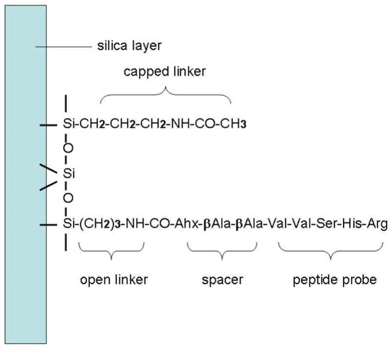
The chemical structure of the acetylated aminosilane linkers on the silica surface and the open linker which connects the spacer, and the pentapeptide. Note that the spacer is bonded with the C-terminus of the peptide.
The starting molecular structure of the pentapeptide RHSVV in simulation A and the spacer Ahx-βAla -βAla were prepared using the Builder Module in the Insight II program 41. The NMR structure of the pentapeptide obtained from the peptide fragment of p53 from the Protein Data Bank (PDB ID: 2FEJ) 42 served as the starting structure in simulation B after the addition of the N-terminal amino group. The starting peptide structure in simulation C was taken from the snapshot at 117-ns from simulation A. The peptide carries 2 positive charges due to the protonated N-terminal amino group and the arginine guanidino side chain. It should be noted that the C-terminal group is neutral because of the covalent bond to the spacer immobilized on the surface. The simulations used explicit salt water to represent the solution phase in contact with the peptide chip. Sodium and chloride ions were added to each system to achieve the 0.14 M salt concentration used in the peptide microarray experiments for comparison.
2. Free peptide in solution
As controls to be compared to the tethered peptide on the chip surface, two free peptide simulations are performed (Table 1 D and E). Both starting structures of the peptide are obtained from the Protein Data Bank (PDB ID: 2FEJ), similar to the starting structure in simulation B. Both N-terminus and C-terminus were added to the peptide. In the chosen set up for simulation D the N-terminal amino group and the arginine guanidino group are protonated and the C-terminal carboxylic group is deprotonated so that the peptide in simulation D has a total net charge of +1. Sodium Chloride at 0.14 M is also present in D. To assess the affect of neutralizing the carboxyl terminus when linked to the surface, the C-terminal group of the peptide in simulation E is neutralized and capped as N-methylamide, so that the peptide has a +2 charge. Here only two Chloride ions have been added to neutralize the solution. A more thorough study of salt concentration effects will be the topic of a future work.
Simulation procedure
Molecular dynamics simulations are carried out using the ESP 43 program in the microcanonical (NVE) ensemble. Glide plane boundary conditions 44 and standard periodic boundary conditions are used for the peptide-chip simulations A, B, C and the free peptide simulations D and E, respectively. Except for the force field parameters of the silica layer, which are adopted from the consistent valence force field (CVFF) 45 and Ref 46, all parameters, the aminosilane derived linkers, the spacer, the pentapeptide, TIP3P waters and the sodium and chloride ions are adopted from the all-atom CHARMM22 proteins force field 47.
During the simulations, all the silica atoms remain fixed; all other bond lengths and the water bond angles are constrained using the RATTLE algorithm 48. The electrostatic interactions are calculated with a fast link-cell Ewald sum 49. The equations of motion are solved with a velocity Verlet integrator 50 with a time step of 2 femtoseconds (fs). During equilibration, the velocities of the atoms are scaled to achieve a temperature of 300 K. The volumes of the simulation boxes are adjusted to achieve a pressure close to 1 atm. The coordinates of the atoms are saved every 0.1 picoseconds (ps) for analysis. The production time of each simulation is 120 nanoseconds (ns).
Analysis
We apply a mass weighted principal component analysis to each molecular dynamics trajectory of the peptide, following the algorithm in Ref 51. Unless stated elsewhere, all atoms of the peptide are used for computing the root-mean-square-deviations (RMSD) weighted by the atomic mass. The radius of gyration has the standard definition as the mass weighted average distance from the center of the mass to every atom in the peptide. We use a convenient pair of meso scale descriptors of peptide structure, the pseudo-dihedral Θ based on 4 consecutive Cα’s and the corresponding triple scalar product Y for the peptide residue RHSV 52. We define the distance of the Arg Cζ atom from the Val5 Cα atom as the peptide end-to-end distance. Relative conformational free energy is calculated using the formula: ΔGi = −kT ln pi where pi is the probability distribution of the peptide end-to-end distance in the ith state. We count conformational transitions when one dominant structure of the peptide changes into another. In order to remove short-time oscillations, 500 ps is considered as the minimal population time defining a dominant conformation.
The interactions between peptide residues and the surface are analyzed using the minimal distance of the side chain heavy atom from the surface terminal methyl layer. The orientation of the tethered peptide relative to the chip surface may be characterized by a peptide-surface angle and the peptide standing height. The definitions we use are arbitrary but instructive. We fit the five Cα atoms of the peptide to a straight line by least squares 53. The angle between the vector representing the direction of the line and the plane formed by the average top methyl layer of the linkers is defined as the angle between the peptide and the surface. We also assign the largest distance of the five α-carbon atoms from the surface as the standing height of the peptide on the surface. In order to capture the perpendicular and parallel movement of the peptide and the spacer on the surface, two distances are calculated: D⊥ defined as the vertical distance between the center of the mass (COM) of the peptide/spacer and the chip surface plane and D// defined as the planar distance between the COM of the peptide/spacer and the open linker to which the peptide is tethered. The correlation coefficient ρX,Y for any two variables can be calculated using the formula: ρX,Y = cov(X,Y)/σ XσY where cov(X, Y) is the covariance of X and Y with σ, the standard deviation.
Results and Discussion
We have three independent simulations (A, B and C) of the tethered peptide on the microarray chip yielding 360 ns total surface sampling time, and the comparison sets including two free peptide simulations (D and E) in the solution for 240 ns of isotropic sampling. As mentioned, the C-terminus of the tethered peptide is neutral due to covalent immobilization to the open linker through the spacer. From here forward, the peptide in simulation D is referred to as ‘the free peptide’ which has charged N- and C-termini, the peptide in simulation E is referred to as ‘the modified free peptide’ which has a charged N-terminus but a modified neutral C-terminus in order to be comparable in charge to the tethered peptide. In all simulations, the pentapeptide RHSVV is found to be very flexible, largely due to its small molecular size. The RMSD can be up to 0.6 nm between different conformations. However, two dominant conformational clusters of the peptide are observed in each free and tethered peptide simulation. In the peptide chip simulations, the initial structure of the spacer Ahx-βAla-βAla is an extended conformation. When the simulation began, the spacer soon collapsed onto the hydrophobic surface and stayed in random coiled forms during the entire simulation. As a result, the pentapeptide is pulled down toward the surface and interacts with the aminosilane derived surface linkers, which tended to remain extended, in part, due to packing constraints on the surface.
1. Cluster of Dominant Conformations
In order to study the peptide structure, we analyze the dominant conformational clusters by means of principal component analysis (PCA). For each simulation, we extract the snapshots from the trajectory at every 10 ps interval within which structures are generally considered correlated. We use the lowest frequency, that is, the first principal component (PC) of each trajectory in further characterization. Snapshots may be rearranged according to the trajectories’ first principal component and thus form a PC ordered data set. The difference in peptide conformation can also be represented by root-mean-square-deviation (RMSD). Two-dimensional RMSD graphical representations constructed from both the original trajectories and PC ordered data sets, where every conformation of the peptide from the snapshots is compared with every other conformation after a least-square translational and rotational fit, are presented in Figure 2. The dominant conformational clusters in the simulation form red or yellow areas with RMSD values smaller than 0.3 nm. The RMSD with respect to time (lower-right triangle) shows the dynamics leading to the kinetic conformational rearrangement of RSHVV. When a stable conformational cluster forms, it usually takes several nanoseconds to change to other conformations. We are also able to observe the reversible folding of peptide into structurally distinct conformational clusters (with RMSD greater than 0.3 nm and up to 0.6 nm, green to blue areas in the RMSD map).
Figure 2.
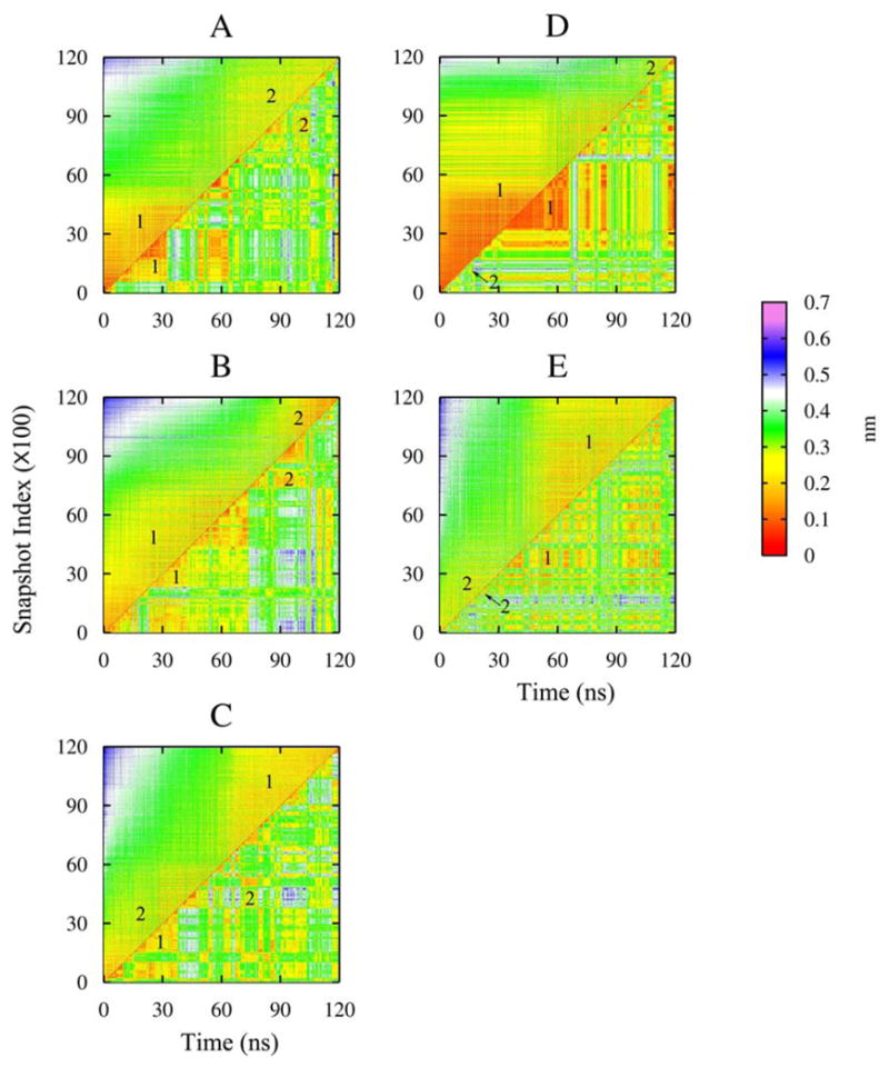
RMSD matrix of each simulation, showing the RMSD of the principal component arranged snapshots according to the first principal components (upper-left triangle) and RMSD with respect to simulation time (lower-right triangle). The dominant conformational clusters are labeled as 1 and 2.
Given several crossings between states, the 120-ns simulation time is sufficient for thermodynamic equilibrium between the different conformational states to be established for the short peptides used here. The RMSD plots of the PC ordered data (upper-left triangle in Figure 2) give us a clear view of the equilibrium constant between conformational clusters. Roughly speaking, the same two dominant conformational clusters (labeled as 1 and 2) exist in each 120-ns simulation. Each cluster appears several times during each 120-ns simulation, but each has a range of duration times and transition frequencies which in aggregate define the kinetics of the system. For each simulation, A-E, we classify A1 to E1 as belonging to cluster 1 and A2 to E2 as cluster 2.
The radius of gyration (Rg) of the peptide in the rearranged trajectory is shown in Figure 3. The Rg of cluster A1 is densely and narrowly distributed between 0.20 nm and 0.25 nm. However, the Rg of cluster A2 is more dispersed, which spans from 0.20 up to 0.40 nm. This suggests that the large scale fluctuations in A1 are less than in A2. Similar situations are observed in the comparisons of the other simulations.
Figure 3.
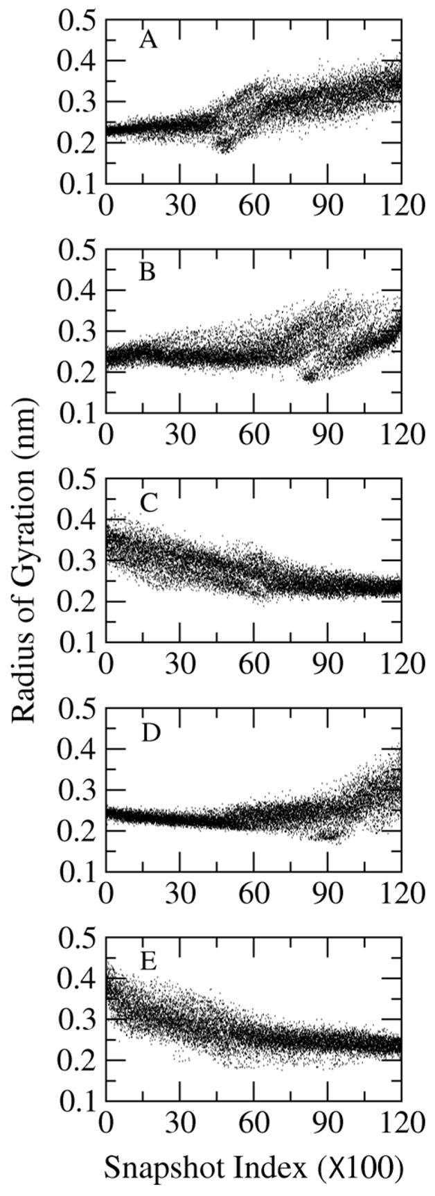
Radius of gyration of the peptide in the principal component arrangement.
In order to further investigate the structures of these conformational clusters, the representative structure of each cluster is calculated as the structure with the minimal RMSD from all peptide conformations within the cluster. Since local geometry such as the bond lengths and angles in the structure can be unrealistically distorted in a simple average, the representative configuration of the conformational cluster is taken from the snapshot with the smallest RMSD to the average structure of the cluster. These conformers are shown in Figure 4. It is obvious that A1, B1, C1, D1 and E1 are in a ‘closed’ form. The positively charged guanidino group of the arginine residue folds back and stays close to the distant backbone carbonyls in a strong H-bond, or a salt bridge. On the other hand, A2, B2, C2, D2 and E2 demonstrate an ‘open’ or extended form, where the arginine side chain moves away from the backbone atoms.
Figure 4.
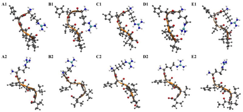
Representative snapshots of the dominant structures of the peptide. Peptide backbone is rendered as orange ribbon. The backbone oxygen atoms, Arg guanidino side chain and N-terminal amino group are colored by atom type. The rest of the peptide atoms are shown in gray.
In order to quantitatively compare the structures among the ten peptide conformational clusters, RMSD between each pair of dominant conformers is shown in Table 2. As expected, RMSD values are greater for comparisons between the representative conformers than between the average structures. The RMSD within cluster 1 varies from 0.10 to 0.17 nm among representative conformers and from 0.05 to 0.09 nm among average structures, while the RMSD within cluster 2 varies from 0.10 to 0.27 nm among representative conformers and from 0.05 to 0.20 nm among average structures. The RMSD between cluster 1 and 2 is larger and differs by 0.34–0.44 nm among representative conformers and by 0.28–0.37 nm among average structures.
Table 2.
RMSD (nm) comparisons among average structures (upper-right triangle) and representative snapshots (lower-left triangle) of dominant conformers. The C-terminal oxygen atom(s) of the peptide are excluded in RMSD calculation.
| A1 | B1 | C1 | D1 | E1 | A2 | B2 | C2 | D2 | E2 | |
|---|---|---|---|---|---|---|---|---|---|---|
| A1 | --- | 0.09 | 0.09 | 0.09 | 0.05 | 0.32 | 0.37 | 0.30 | 0.34 | 0.31 |
| B1 | 0.15 | --- | 0.08 | 0.08 | 0.07 | 0.30 | 0.37 | 0.28 | 0.32 | 0.29 |
| C1 | 0.16 | 0.15 | --- | 0.08 | 0.08 | 0.31 | 0.37 | 0.29 | 0.33 | 0.30 |
| D1 | 0.17 | 0.12 | 0.15 | --- | 0.07 | 0.33 | 0.39 | 0.31 | 0.35 | 0.32 |
| E1 | 0.10 | 0.13 | 0.14 | 0.15 | --- | 0.30 | 0.36 | 0.28 | 0.32 | 0.30 |
| A2 | 0.36 | 0.40 | 0.38 | 0.42 | 0.38 | --- | 0.19 | 0.07 | 0.06 | 0.05 |
| B2 | 0.39 | 0.43 | 0.41 | 0.44 | 0.41 | 0.23 | --- | 0.19 | 0.17 | 0.20 |
| C2 | 0.36 | 0.38 | 0.38 | 0.40 | 0.37 | 0.17 | 0.27 | --- | 0.09 | 0.08 |
| D2 | 0.34 | 0.38 | 0.37 | 0.40 | 0.36 | 0.11 | 0.20 | 0.18 | --- | 0.06 |
| E2 | 0.36 | 0.39 | 0.38 | 0.41 | 0.37 | 0.10 | 0.23 | 0.15 | 0.11 | --- |
The distinct arrangement of the peptide backbone is the major structural difference between cluster 1 and cluster 2. Classic Ramachandran dihedral angle analysis would require five adjacent φ, ψ pairs to characterize the secondary structure for this system and fails to yield a clear graphical analysis. Therefore, in order to more efficiently characterize the arrangement and orientation of Cα atoms and peptide groups in the two cluster collections, we use a simplified two dimensional representation (a pseudo-dihedral Θ and a triple scalar product Y) to reduce the number of degrees of freedom.
Figure 5 shows the distinct distribution of Θ and Y of the first four neighboring residues (RHSV) in cluster 1 and cluster 2. It is not necessary to show the representation of the last four neighboring residues, HSVV, because the fifth residue is flexible in both clusters. The Y values of cluster 1 are distributed mainly below 0 while most Y values of cluster 2 are above 0, illustrating that the peptide backbone dipoles adopt different orientations in the two clusters. The pseudo-dihedral angle of cluster 1 lies mainly between −60° to 90°, indicating that the peptide is in a ‘closed’ conformation. The bending of Arg1 and Val4 C α atoms toward each other enables the favorable short-ranged electrostatic interactions between the charged and partially charged groups, respectively. As seen from the tethered peptide (A1, B1 and C1) and the free peptide with neutral C-terminus (E1) in Figure 4, the positively charged arginine guanidino side chain stays close to the peptide backbone oxygen atoms of Ser3, Val4 and Val5. The arginine side chain of the normal peptide (D1) folds back to the C-terminus to favor the formation of a salt bridge between the guanidino group and the carboxylic group of Val5. No water molecules can be found between these two oppositely charged groups after salt bridge formation. The oxygen atoms from the carboxylic terminus are in direct contact with the hydrogen atoms of guanidino group. The intramolecular salt bridge interactions are found to be prevalent in cluster 1 and stabilize the peptide. The Θ angles of cluster 2 are centered at ± 180°, which indicates that the peptide adopts an extended structure. The N- and C- terminal groups extend away from each other. But the charged peptide groups show distinct intermolecular electrostatic correlations and therefore, interactions with the ions in the solution phase.
Figure 5.
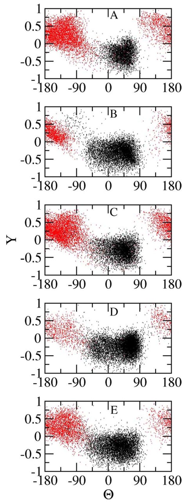
Θ, Y maps of cluster 1 (black) and cluster 2 (red) in each simulation.
The peptide end-to-end distance, the distance between the Arg side chain and the backbone of the terminal residue Val5 is another parameter that can directly distinguish the two major conformations, compact and extended. The dominant conformational clusters appear as the valleys of the configurational free energy in Figure 6. The energy barrier between the compact and the extended form is small. The peptide is able to change from one dominant conformation to another. Clusters 1 and 2 are almost equally accessible in the conformational space of the tethered and modified free peptide. Yet, D1 forms a deep and narrow well while D2 is shallow and flat. If we use 1 nm as the distance criteria to distinguish the two major conformations, the end-to-end distance is less than 1 nm in cluster 1, the compact form, and the distance is greater than 1 nm in cluster 2, the extended form.
Figure 6.
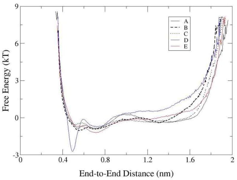
Configurational free energy with respect to the end-to-end distance.
The ratio of integrated time spent in a cluster with respect to another cluster determines the equilibrium constant between the conformations. The equilibrium ratio of cluster 1 to cluster 2 is 1.1, 1.7 and 1.1 (for an average of 1.3) in the tethered peptide simulations A, B, and C, 4.9 in the free peptide simulation D, and 1.9 in the modified peptide E, respectively. Thus, while the tethered peptide is more similar in its conformational manifold to the solution state with a neutral C-terminal, the difference is small for equilibrium constant; less than a factor of 4. This means that the experimentally assumed hypothesis that the tethered peptide presents similar conformations to the untethered peptide is indeed substantiated in this instance by this study.
We observe distinct conformational accessibility or dynamic transition likelihood differences between the tethered and free peptide. D1 accounts for 83% of the entire peptide conformation ensemble and is energetically very stable largely due to the strong salt bridge interactions between the charged arginine guanidino and carboxylic groups. Conformational transitions from cluster 1 to 2 are about five times less frequent for the free peptide in solution. In one instance cluster D1 stays in that cluster for 36.6 ns. In contrast, the longest duration time of cluster D2 is 2.2 ns. The conformational equilibrium is similar between the tethered peptide and modified free peptide. However, the kinetics of conformational transitions is significantly altered. The modified free peptide changes its structure more frequently between the two major conformations than the tethered one. Conformational transitions occur 5, 6, and 9 times in the peptide chip simulations A, B, and C, 5 times in the free peptide simulation D but 15 times in the charge modified peptide simulation E during the 120-ns. Moreover, both the dominant conformational clusters of the tethered peptide could last for more than 10 ns, sometimes up to 25 ns, whereas the longest duration time of cluster E1 and E2 is 9.9 ns and 2.9 ns, respectively. Similar to the free peptide, the life time of the extended conformation of the modified peptide is greatly reduced.
The chip surface tends to somewhat stabilize the extended peptide conformation not unlike what happens with the neutral C-terminus peptide E. Therefore, although a peptide near the surface can exist in a similar structural form as the peptide free in the solution, the presence of the chip surface has changed both the thermodynamic equilibrium and kinetics of the two dominant conformational clusters. Charge groups clearly play a role.
2. Peptide-Surface Interaction and Orientation
Figure 7 shows a snapshot of the peptide on the microarray surface. The aminosilane layer together with the silica surface is 0.92 nm thick, with a small deviation in the three peptide microarray simulations because of the somewhat tight packing of the linkers. Thus, the top layer of the chip surface formed by the methyl groups of the unreacted aminosilane derived linkers has small fluctuations. The neutral and hydrophobic surface chemistry originating from the methyl terminated functional groups dominates the nature of the peptide-surface interactions and peptide orientation for this system.
Figure 7.
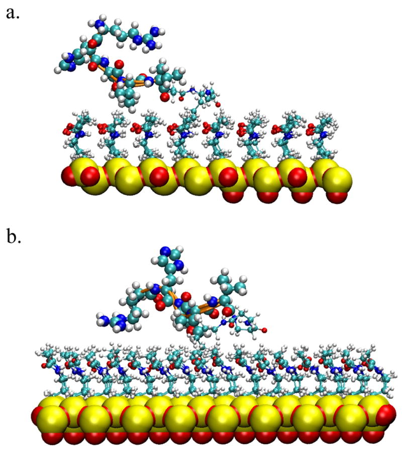
Snapshots of the peptide on surface. a. the peptide is in a ‘closed’ conformation b. the peptide is in an ‘open’ conformation.
The tethered peptide makes and breaks contact with the surface at various points. We use 0.35 nm, about the minimum distance between a carbon atom in the peptide with a surface atom, as the criterion for direct surface contact and the percentage of time when each residue forms direct contact with the surface is shown in Table 3. Because of sufficient sampling, the peptide-surface interactions are similar in each simulation: the hydrophobic residues tend to lie close to the surface, forming stable hydrophobic interactions with the methyl terminal groups of the surface while the hydrophilic or charged residues tend to stay away from the neutral hydrophobic surface. When we compare the whole trajectory of each simulation the Val4 and Val5 residues at the C-terminus of the pentapeptide, which are tethered to the surface through the spacer, constantly interact with the surface demonstrating these hydrophobic interactions. The two hydrophilic amino acid residues His2 and Ser3 make less contact with the surface. The interactions between the positively charged Arg1 residue and the hydrophobic surface are unstable and transient.
Table 3.
Contact frequency (in percentage) of each residue with the surface
| Arg1 | His2 | Ser3 | Val4 | Val5 | |
|---|---|---|---|---|---|
| Simulation A | 20.0 | 37.8 | 37.8 | 53.9 | 73.9 |
| Cluster A1 | 4.0 | 64.9 | 69.3 | 52.6 | 72.7 |
| Cluster A2 | 31.4 | 18.0 | 15.4 | 56.8 | 73.7 |
| Simulation B | 13.9 | 22.6 | 21.9 | 61.5 | 53.5 |
| Cluster B1 | 5.1 | 31.8 | 26.5 | 59.0 | 51.7 |
| Cluster B2 | 38.0 | 0.6 | 25.0 | 72.7 | 42.5 |
| Simulation C | 16.0 | 18.0 | 5.7 | 50.9 | 50.1 |
| Cluster C1 | 9.7 | 11.1 | 8.0 | 48.5 | 58.6 |
| Cluster C2 | 21.7 | 24.7 | 2.8 | 54.5 | 41.1 |
When we compare the contact frequency of dominant clusters in the peptide chip simulations, we notice that the contact frequency of the charged residue, Arg, with the surface in cluster 2 is always higher than in cluster 1. As a matter of fact, the Arg residue in clusters A1 and B1 interact with the surface eight times more frequently than those in A2 and B2. The more frequent surface interaction is made possible because the Arg side chain stretches away from the peptide backbone in the extended conformation in cluster 2 rather than being constrained close to the backbone oxygen as in cluster 1.
Given the different surface contact frequencies between the two clusters, we want to further investigate if there is any orientational preference for the individual conformations. To address this question, the peptide-surface angle and the standing height of the peptide are calculated. We define the peptide-surface angle fluctuating between 0° and 30° as a parallel orientation, between 30° and 60° as a tilted orientation and between 60° and 90° as a perpendicular orientation. As shown in Figure 8, the peptide frequently changes its orientation on the chip surface. We observe that over 85% of the time, in each chip simulation, the peptide stays parallel or significantly tilted to the surface, making numerous van der Waals interactions between the hydrophobic groups of the peptide (Val4 and Val5 side chain) and the surface.
Figure 8.
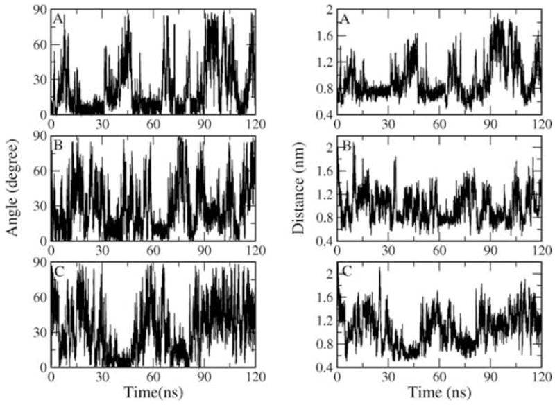
Orientation of the peptide on surface (left) and standing height of peptide from the surface (right) as a function of time in simulations A, B and C.
Similar to the orientation, the peptide frequently changes its distance from the chip surface as well. The standing height of the peptide correlates well with the orientation. The correlation coefficient is 0.93 for simulation A, 0.74 for simulation B and 0.91 for simulation C. When the peptide stays parallel to the surface, the peptide backbone carbon atoms are close to the surface and often without any intervening waters. When we compare the RMSD map in Figure 2 with the peptide orientation, we observe that in simulation A the peptide visits parallel orientations to the surface during which the ‘closed’ conformation prevails. In simulation B when the ‘closed’ conformation dominates the peptide changes twice from the perpendicular to the parallel orientation. Towards the end of that simulation, the peptide stays tilted to the surface while maintaining an ‘open’ form.
We notice that when the peptide changes from one conformation to another, there is usually an accompanying peptide orientational rearrangement. However, no simple orientational preference is found for either the ‘closed’ or the ‘open’ peptide conformation. Overall, the orientational rearrangement of the peptide is more frequent than the conformational change which sometimes takes tens of nanoseconds. The observation that the peptide could remain in the same conformation while changing its orientation to the surface is in agreement with a molecular simulation of the adsorption of a fibrinogen γ-chain which showed that the adsorbed protein reoriented itself to maximize the favorable interaction with the SAM surface while no significant protein conformational changes occurred during the simulation time 27. We expect that as the molecular weight of the protein increases, the kinetics of the major conformational changes would be even slower than the kinetics of the orientational rearrangement.
3. Movement of the Peptide on the Surface
Though covalently tethered on the surface, the peptide is found to have limited lateral mobility. The linear spacer Ahx-βAla -βAla was designed in microarray experiments to provide space and increase the flexibility in the perpendicular and parallel movement of the peptide over the surface. The translational motions of the peptide and spacer are plotted in Figure 9. Obviously, both the planar (D//) and vertical motion (D⊥) of the peptide are greater than the spacer. The average parallel distance of the peptide from the surface linker is 1.22 ± 0.41 (mean ± standard deviation) nm, 1.19 ± 0.45 and 1.07 ± 0.39 whereas the average parallel distance of spacer from the surface open linker is 0.76 ± 0.10, 0.83 ± 0.12 and 0.72 ± 0.10 in simulation A, B and C, respectively. The correlation coefficient of the planar movement of the peptide and spacer is 0.63, 0.50 and 0.32 in the three peptide chip simulations. The addition of the spacer between the peptide and the open linker provides some flexibility in the planar motion of the peptide over the surface.
Figure 9.
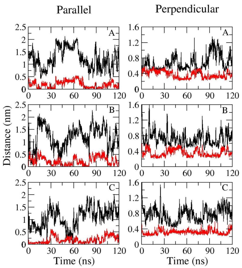
Parallel and perpendicular movement of the peptide (black) and spacer (red) as a function of time in simulation A, B and C.
The spacer Ahx-βAla -βAla is linear but hydrophobic. Therefore, the spacer remains in a coiled form and constantly interacts with the hydrophobic surface. Both the peptide and the spacer are thus restrained close to the hydrophobic surface. The COM of the spacer retains an almost constant separation distance from the surface for each simulation and less than a 0.2 nm difference between simulations. The average perpendicular distance of the peptide from the surface is 0.68 ± 0.19, 0.72 ± 0.18 and 0.77 ± 0.18 nm whereas the average vertical distance of spacer from the surface is 0.60 ± 0.05, 0.57 ± 0.04 and 0.43 ± 0.03 nm in simulation A, B and C, respectively. There is no distinct correlation between the vertical motion of the spacer and the peptide as the correlation coefficient with the perpendicular movement is −0.29, 0.13 and −0.06 in the three peptide chip simulations. However, both the perpendicular movement of the peptide and spacer are severely restrained by the stable hydrophobic interactions with the surface.
Surface chemistry in conjunction with the linear length of the spacer determines the separation distance of the peptide from the surface in our simulations of a peptide microarray. Since the orientation and accessibility of the protein/peptide probe is essential to the efficiency of the binding assay in protein microarrays, the appropriate choice of the microarray surface might be to move the bound probe away, enhance the accessibility of the target in the solution phase and produce faster and more efficient target binding (detection). One suggestion in this case would be the modification of the surface chemistry, for example, from hydrophobic to hydrophilic or even charged. The spacer or the peptide probes might be repelled by the chip surface. Thus, the peptide would possibly be more accessible to the target molecules and enhance the binding capability in the solution phase. However, issues of nonspecific binding, conformational change, protein destabilization and even denaturation, can be the result of surface modification of the microarray.
Conclusions
In this paper, we presented all-atom molecular dynamics simulations of a peptide tethered on a microarray surface and free in solution. Our pentapeptide RHSVV model confirms the hypothesis that there exist structurally similar conformations both when near the prepared surface and free in the aqueous solution. However, both the thermodynamic equilibrium and the kinetics of dominant structures are significantly affected by the presence of the surface. We found that the spacer molecules often used to achieve greater or lesser proximity effects may compound the hydrophobic effects for a particular peptide. In the cases studied here we found that charge groups clearly play a role in the conformational equilibrium.
The peptide-microarray simulations give us insights into the peptide conformation-surface correlations. The orientation of the peptide on a prepared surface and the translational flexibility of the peptide on the chip directly influence its accessibility and kinetics. The nature of the surface being hydrophobic or hydrophilic determines specific peptide-analyte interactions through conformational modulation. This ultimately has design implications as this restrains the peptide/protein motion, therefore the accessibility, on the chip. This should be an important consideration factor in designing the parameters of peptide/protein microarrays.
Acknowledgments
JF, KYW, GCL, and BMP gratefully thank the National Institutes of Health (R01 GM066813) and the Robert A Welch Foundation (E-1028) for partial financial support of this work. Computational resources for this research were supported in part by the National Science Foundation through TeraGrid resources provided by the Pittsburgh Supercomputing Center (Lemieux and Bigben) and the San Diego Supercomputer Center (Datastar) and the Molecular Science Computing Facility (MSCF) in the William R. Wiley Environmental Molecular Sciences Laboratory, a national scientific user facility sponsored by the U.S. Department of Energy’s Office of Biological and Environmental Research and located at the Pacific Northwest National Laboratory, operated for the Department of Energy by Battelle. XG acknowledges the supports of NIH/GM/AI (R43 GM076941, 1R21CA126209) and the R. A. Welch Foundation (E-1270).
References
- 1.Balboni I, Chan SM, Kattah M, Tenenbaum JD, Butte AJ, Utz PJ. Annu Rev Immunol. 2006;24:391. doi: 10.1146/annurev.immunol.24.021605.090709. [DOI] [PubMed] [Google Scholar]
- 2.Groathouse NA, Amin A, Marques MA, Spencer JS, Gelber R, Knudson DL, Belisle JT, Brennan PJ, Slayden RA. Infect Immun. 2006;74:6458. doi: 10.1128/IAI.00041-06. [DOI] [PMC free article] [PubMed] [Google Scholar]
- 3.Jones RB, Gordus A, Krall JA, MacBeath G. Nature. 2006;439:168. doi: 10.1038/nature04177. [DOI] [PubMed] [Google Scholar]
- 4.Haab BB. Curr Opin Biotechnol. 2006;17:415. doi: 10.1016/j.copbio.2006.06.013. [DOI] [PubMed] [Google Scholar]
- 5.Cretich M, Damin F, Pirri G, Chiari M. Biomol Eng. 2006;23:77. doi: 10.1016/j.bioeng.2006.02.001. [DOI] [PubMed] [Google Scholar]
- 6.Min DH, Mrksich M. Curr Opin Chem Biol. 2004;8:554. doi: 10.1016/j.cbpa.2004.08.007. [DOI] [PubMed] [Google Scholar]
- 7.Buijs J, Norde W, Lichtenbelt JWT. Langmuir. 1996;12:1605. [Google Scholar]
- 8.Kondo A, Murakami F, Higashitani K. Biotechnol Bioeng. 1992;40:889. doi: 10.1002/bit.260400804. [DOI] [PubMed] [Google Scholar]
- 9.Norde W, Giacomelli CE. J Biotechnol. 2000;79:259. doi: 10.1016/s0168-1656(00)00242-x. [DOI] [PubMed] [Google Scholar]
- 10.Mitchell P. Nat Biotechnol. 2002;20:225. doi: 10.1038/nbt0302-225. [DOI] [PubMed] [Google Scholar]
- 11.Angenendt P, Glokler J, Murphy D, Lehrach H, Cahill DJ. Anal Biochem. 2002;309:253. doi: 10.1016/s0003-2697(02)00257-9. [DOI] [PubMed] [Google Scholar]
- 12.Kusnezow W, Hoheisel JD. J Mol Recognit. 2003;16:165. doi: 10.1002/jmr.625. [DOI] [PubMed] [Google Scholar]
- 13.Guilleaume B, Buness A, Schmidt C, Klimek F, Moldenhauer G, Huber W, Arlt D, Korf U, Wiemann S, Poustka A. Proteomics. 2005;5:4705. doi: 10.1002/pmic.200401324. [DOI] [PubMed] [Google Scholar]
- 14.Ajikumar PK, Ng JK, Tang YC, Lee JY, Stephanopoulos G, Too HP. Langmuir. 2007;23:5670. doi: 10.1021/la063717u. [DOI] [PubMed] [Google Scholar]
- 15.Peluso P, Wilson DS, Do D, Tran H, Venkatasubbaiah M, Quincy D, Heidecker B, Poindexter K, Tolani N, Phelan M, Witte K, Jung LS, Wagner P, Nock S. Anal Biochem. 2003;312:113. doi: 10.1016/s0003-2697(02)00442-6. [DOI] [PubMed] [Google Scholar]
- 16.Yeo DS, Panicker RC, Tan LP, Yao SQ. Comb Chem High T Scr. 2004;7:213. doi: 10.2174/1386207043328823. [DOI] [PubMed] [Google Scholar]
- 17.Renberg B, Shiroyama I, Engfeldt T, Nygren PK, Karlstrom AE. Anal Biochem. 2005;341:334. doi: 10.1016/j.ab.2005.03.039. [DOI] [PubMed] [Google Scholar]
- 18.Lee JM, Park HK, Jung Y, Kim JK, Jung SO, Chung BH. Anal Chem. 2007;79:2680. doi: 10.1021/ac0619231. [DOI] [PubMed] [Google Scholar]
- 19.Rusmini F, Zhong Z, Feijen J. Biomacromolecules. 2007;8:1775. doi: 10.1021/bm061197b. [DOI] [PubMed] [Google Scholar]
- 20.Gray JJ. Curr Opin Struct Biol. 2004;14:110. doi: 10.1016/j.sbi.2003.12.001. [DOI] [PubMed] [Google Scholar]
- 21.Wertz CF, Santore MM. Langmuir. 2002;18:1190. [Google Scholar]
- 22.Burkett SL, Read MJ. Langmuir. 2001;17:5059. [Google Scholar]
- 23.Zhou J, Tsao HK, Sheng YJ, Jiang S. J Chem Phys. 2004;121:1050. doi: 10.1063/1.1757434. [DOI] [PubMed] [Google Scholar]
- 24.Basalyga DM, Latour RA. J Biomed Mater Res A. 2003;64A:120. doi: 10.1002/jbm.a.10360. [DOI] [PubMed] [Google Scholar]
- 25.Cormack AN, Lewis RJ, Goldstein AH. J Phys Chem B. 2004;108:20408. [Google Scholar]
- 26.Wilson K, Stuart SJ, Garcia A, Latour RA. J Biomed Mater Res A. 2004;69A:686. doi: 10.1002/jbm.a.30042. [DOI] [PubMed] [Google Scholar]
- 27.Agashe M, Raut V, Stuart SJ, Latour RA. Langmuir. 2005;21:1103. doi: 10.1021/la0478346. [DOI] [PubMed] [Google Scholar]
- 28.Davis JJ, Tkac J, Laurenson S, Ferrigno PK. Anal Chem. 2007;79:1089. doi: 10.1021/ac061863z. [DOI] [PubMed] [Google Scholar]
- 29.Cha T, Guo A, Zhu XY. Proteomics. 2005;5:416. doi: 10.1002/pmic.200400948. [DOI] [PubMed] [Google Scholar]
- 30.Groll J, Amirgoulova EV, Ameringer T, Heyes CD, Rocker C, Nienhaus GU, Moller M. J Am Chem Soc. 2004;126:4234. doi: 10.1021/ja0318028. [DOI] [PubMed] [Google Scholar]
- 31.Amirgoulova EV, Groll J, Heyes CD, Ameringer T, Rocker C, Moller M, Nienhaus GU. Chemphyschem. 2004;5:552. doi: 10.1002/cphc.200400024. [DOI] [PubMed] [Google Scholar]
- 32.Shang J, Geva E. J Phys Chem B. 2005;109:16340. doi: 10.1021/jp052275c. [DOI] [PubMed] [Google Scholar]
- 33.Knotts TAt, Rathore N, de Pablo J. Proteins. 2005;61:385. doi: 10.1002/prot.20581. [DOI] [PubMed] [Google Scholar]
- 34.Friedel M, Baumketner A, Shea JE. Proc Natl Acad Sci USA. 2006;103:8396. doi: 10.1073/pnas.0601210103. [DOI] [PMC free article] [PubMed] [Google Scholar]
- 35.Pellois JP, Zhou X, Srivannavit O, Zhou T, Gulari E, Gao X. Nat Biotechnol. 2002;20:922. doi: 10.1038/nbt723. [DOI] [PubMed] [Google Scholar]
- 36.Wong KY, Pettitt BM. Theor Chem Acc. 2001;106:233. [Google Scholar]
- 37.Wong KY, Pettitt BM. Biopolymers. 2004;73:570. doi: 10.1002/bip.20004. [DOI] [PubMed] [Google Scholar]
- 38.Wong KY, Vainrub A, Powdrill T, Hogan M, Pettitt BM. Mol Simulat. 2004;30:121. [Google Scholar]
- 39.Pellois JP, Wang W, Gao X. J Comb Chem. 2000;2:355. doi: 10.1021/cc0000139. [DOI] [PubMed] [Google Scholar]
- 40.Fodor SP, Read JL, Pirrung MC, Stryer L, Lu AT, Solas D. Science. 1991;251:767. doi: 10.1126/science.1990438. [DOI] [PubMed] [Google Scholar]
- 41.Computational results obtained using the InsightII program from Accelrys Inc. through a cooperative with the Institute for Molecular Design
- 42.Canadillas JM, Tidow H, Freund SM, Rutherford TJ, Ang HC, Fersht AR. Proc Natl Acad Sci USA. 2006;103:2109. doi: 10.1073/pnas.0510941103. [DOI] [PMC free article] [PubMed] [Google Scholar]
- 43.Smith PE, Holder ME, Dang LX, Feig M, Lynch GC, Wong K-y, Pettitt BM. University of Houston; 1996. [Google Scholar]
- 44.Wong KY, Pettitt BM. Chem Phys Lett. 2000;326:193. [Google Scholar]
- 45.Discover2.9.8/96.0. San Diego, CA 1996.
- 46.Rovere M, Ricci MA, Vellati D, Bruni F. J Chem Phys. 1998;108:9859. [Google Scholar]
- 47.MacKerell AD, Bashford D, Bellott M, Dunbrack RL, Evanseck JD, Field MJ, Fischer S, Gao J, Guo H, Ha S, Joseph-McCarthy D, Kuchnir L, Kuczera K, Lau FTK, Mattos C, Michnick S, Ngo T, Nguyen DT, Prodhom B, Reiher WE, Roux B, Schlenkrich M, Smith JC, Stote R, Straub J, Watanabe M, Wiorkiewicz-Kuczera J, Yin D, Karplus M. J Phys Chem B. 1998;102:3586. doi: 10.1021/jp973084f. [DOI] [PubMed] [Google Scholar]
- 48.Andersen HC. J Comput Phys. 1983;52:24. [Google Scholar]
- 49.W dLS, W PJ, R SE. P Roy Soc Lond A Mat. 1980;373:27. [Google Scholar]
- 50.William CS, Hans CA, Peter HB, Kent RW. J Chem Phys. 1982;76:637. [Google Scholar]
- 51.Hess B. Phys Rev E. 2002;65:031910. doi: 10.1103/PhysRevE.65.031910. [DOI] [PubMed] [Google Scholar]
- 52.Smith PE, Blatt HD, Pettitt BM. Proteins. 1997;27:227. [PubMed] [Google Scholar]
- 53.Shakarji CM. J Res Nat Inst Stan. 1998;103:633. doi: 10.6028/jres.103.043. [DOI] [PMC free article] [PubMed] [Google Scholar]


