Abstract
A novel microfluidic surface-based competition immunoassay, termed the concentration gradient immunoassay (CGIA, described in detail in a companion paper1) uses surface plasmon resonance (SPR) imaging to rapidly measure the concentration of small molecules. To conduct this assay, antibody and analyte are introduced into the two inlets of a T-sensor.2, 3 Several millimeters downstream, antibody molecules with open binding sites can bind to a surface functionalized with immobilized antigen. This space- and time-dependent binding can be sensitively observed using SPR imaging. In this paper, we describe a complex three-dimensional finite element model developed to better understand the dynamic processes occurring with this assay. The model shows strong qualitative agreement with experimental results for small molecule detection. The model confirms the experimental finding that the position within the microchannel at which the antibody binds to the immobilized analyte may be used to quantify the concentration of analyte. In addition, the model was used to explore the sensitivity of assay performance to parameters such as antibody and analyte concentrations, thereby giving insight into ways to optimize analysis speed and accuracy. Given the experimental verification of the computational results, this model serves as an efficient method to explore the influence of the flow rate, microchannel dimensions, and antibody concentration on the sensitivity of the assay.
Keywords: Immunoassay, finite element method, numerical modeling, fluid mechanics, microfluidics
Introduction
Rapid, quantitative microfluidic immunoassays have the potential to significantly improve healthcare by reducing reagent and sample volumes, yielding more timely results, detecting a wide range of analytes, and bringing the test to the patient.4–6 Numerous microfluidic flow immunoassay formats7–21 have been developed to create such a diagnostic platform.
Our group has proposed a novel surface-based microfluidic flow immunoassay – the concentration gradient immunoassay (CGIA) – to quantify small molecules using surface sensitive techniques such as SPR imaging.1 This assay extends the principles of the diffusion immunoassay (DIA)19–21 – an assay that utilizes the unique transport characteristics of microfluidic devices like the T-sensor.2, 3 Like the DIA, this assay relies upon the interdiffusion and binding of an antibody and analyte to quantify the concentration of the analyte. In contrast to the DIA, which uses fluorescence to observe the assay outcome, the CGIA uses SPR imaging to measure changes in mass at a surface to quantify the analyte.22–24
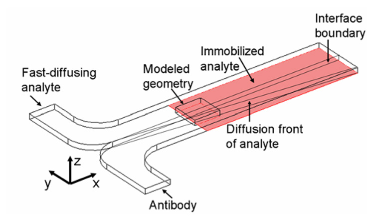
A full description of the CGIA can be found in a companion paper that provides experimental results which confirm the computational findings presented in this paper.1 Briefly, in this assay (Figure 1), solutions of antibody and antigen (the analyte) are introduced to a T-sensor under laminar flow conditions. The solutions mix by diffusion across the interface, allowing the antibody and analyte to bind to form antibody-analyte complex. This diffusion-based mixing establishes a spatially-dependent concentration gradient of antibody-analyte complex that can be directly related to the concentration of analyte for a given antibody concentration. Twenty-two millimeters downstream of the inlet the surface of the microchannel is functionalized with immobilized analyte. Antibody with available analyte binding sites binds to this surface and is detected with SPR imaging. The amount and location of antibody with available binding sites directly relates to the amount of analyte in solution. The higher the analyte concentration, the farther from the fluidic interface is antibody available to bind to the surface due to the formation of antibody-antigen complex. This shift in the antibody binding profile from the fluidic interface, known as the “assay shift,” has been shown experimentally and with the following model to reliably quantify the analyte concentration. The sensitivity of the CGIA will depend on numerous assay parameters including the diffusivity of the analyte and antibody molecules, the flow rate, the kinetic parameters of the antibody/analyte binding, and the to give insight into the dynamic processes occurring in the assay as well as verify experimental concentration of antibody.
Figure 1.
Schematic of the concentration gradient immunoassay (not drawn to scale). Antibody and a fast-diffusing analyte (e.g., phenytoin) are introduced to a T-sensor. Antibody and analyte interdiffuse and bind at the fluidic interface. The diffusion front of the fast-diffusing analyte traverses into the antibody stream (y-dimension) as the fluids travel down the length of the channel where it binds to the relatively slow-diffusing antibody to form antibody-analyte complex. The surface downstream is functionalized with immobilized analyte. Free antibody binds to the surface and is detected with a surface-sensitive technique – SPR imaging. Due to computational limitations, only the central 1.6 mm of the 3 mm wide (y-dimension) device located 22 mm downstream of the inlet could be modeled in three dimensions. A two-dimensional model that was connected to the three-dimensional model simulated the upstream portion of the assay.
This paper describes a finite element model of the CGIA that is shown to qualitatively confirm the experimental findings (see the accompanying paper). The development of a computational model is important to aid in the understanding of the dynamic processes occurring in this assay. Unlike many immunoassays such as an ELISA, which are conducted under pseudo-equilibrium conditions and take several hours to entire days to complete, this assay is conducted quickly (less than 15 minutes), far from equilibrium or steady-state conditions. Previous computational models have highlighted unique mass transport properties in T-sensor microchannels3 which could significantly impact the sensitivity of this assay. The model also gives insight into the concentration profile of the antibody, antibody-analyte complex, and analyte within the microchannel. This information cannot be provided experimentally with the current method of detection (SPR-imaging), which uses an evanescent field to detect the binding of the antibody to the surface.
Only the central 1.6 mm of the 3-mm-wide (y-dimension) microchannel positioned twenty-two millimeters downstream of the inlet could be modeled in three-dimensions (Figure 1) due to computational constraints. Because of its reduced complexity in the absence of surface binding, a two-dimensional model simulated the convective and diffusive mass transport and antibody antigen binding from the inlet to the binding surface. The solution to this two-dimensional model was coupled to a full three-dimensional model that includes binding of antibody (assumed to be monovalent) to the SPR sensing surface. The governing equations within the microchannel are the Navier-Stokes equation,25 which describes the behavior of the fluids, and the convection-diffusion equation,25 which describes the transport and reaction of the antibody, analyte, and antibody-analyte complex. The surface reaction of the antibody binding to a surface-immobilized analyte (Equations 1 and 2) was coupled to the convection-diffusion equation for the antibody within the microchannel. See Supporting Information for further details.
| Eqn(1) |
| Eqn(2) |
where cAb is the antibody concentration in the bulk of the microchannel, cs is the surface concentration of bound antibody, θ is the surface concentration of antibody binding sites, θ0 is the initial surface concentration of antibody binding sites, and kads and kdes are the adsorption and desorption kinetic parameters.
Computational Simulations
All computational simulations were completed with the commercially-available finite element method software, COMSOL® (Version 3.3, Comsol, Inc., Burlington, MA) on a G5 PowerMAC with 8 GB of RAM and dual 2.5 GHz processors. The models build upon a two-dimensional example in COMSOL®’s model library.26
A two-dimensional cross-section (y- and z-dimensions) of the microfluidic device simulated the concentration profiles of the antibody, analyte, and antibody-analyte complex as a function of the x-dimension for the 22 mm portion of the device upstream of the binding region. In these simulations, the entire width of the microchannel (3 mm in the y-dimension) was modeled. The Poisson equation solved the laminar flow parabolic velocity profile. A pseudo-3d convection-diffusion mode used this velocity profile to determine the concentration profiles of the analyte, antibody, and antibody-analyte complex as the streams flow down the length of the device. The concentration and velocity profiles were mapped to the inlet of the three-dimensional geometry to connect the two- and three-dimensional models.
The three-dimensional geometry (Figure 1) contained the binding surface and was 1 mm (x-dimension) × 1.6 mm (y-dimension) × 0.1 mm (z-dimension) for analyte concentrations ranging from 1 nM to 500 nM. Additional simulations (data not shown) demonstrated that the model results are representative of the assay for this range of analyte concentrations. For higher analyte concentrations, the modeled three-dimensional geometry was 0.3 mm (x-dimension) × 3 mm (y-dimension) × 0.1 mm (z-dimension) to accurately capture the steep concentration gradient of the analyte.
The steady-state Navier-Stokes equation was solved using a mapped two-dimensional velocity profile at the inlet thereby ensuring fully-developed flow throughout the device. COMSOL®’s weak-boundary mode solved the surface reaction and coupled it to the flux of antibody through the binding surface in boundary conditions of the COMSOL®’s convection-diffusion mode solved in the bulk of microchannel. Using the mapped two-dimensional concentration profiles at the inlet and the solved three-dimensional velocity profile, the transient convection-diffusion mode and weak boundary mode were solved simultaneously. The initial conditions specified that the concentration of all species was zero within the microchannel and no antibody was bound to the surface.
For the portion of the microchannel modeled using the pseudo-3d mode, it was assumed that the diffusion was minimal in the axial direction (x-dimension) compared to convection; this is an acceptable description for this model. In the experimental design (described in detail in [1]), bovine serum albumin (BSA) molecules functionalized with multiple analytes are adsorbed to a surface and bind antibody from solution. Given the dimensions of an antibody (14.2 nm × 8.5 nm × 3.8 nm)27 and bovine serum albumin (BSA) (~71 nm2 when adsorbed to a surface)28 and taking into account steric constraints and that multiple analyte binding sites are available on a single BSA molecule, the surface density was estimated to be 1 binding site every 5 nm × 5 nm (6.64 × 10⁻⁸ moles/m2). The diffusion coefficient for the model analyte, phenytoin (FW 361), used in experimental tests of this system1 was estimated as 5×10⁻⁶ cm2s−1. This is comparable to the diffusion coefficient of other small molecules such as sucrose (MW 342 Da) with a reported diffusion coefficient of 4.6×10⁻⁶ cm2s−1.29 The modeled diffusion coefficient of the antibody was 4.3×10⁻⁷ cm2s−1 based on molecular weight (150 kDa).19, 27 The diffusion coefficient of the antibody-analyte complex was assumed to be the same as the antibody given the large size of the antibody relative to the phenytoin molecule. The kads (105 M−1s−1) was estimated to be an order of magnitude smaller than the antibody-analyte binding rate in solution, kon (106 M−1s−1), due to the reduction of binding efficiency of an immobilized analyte versus an analyte free in solution.30 The antibody-antigen dissociation rate in solution, koff, and kdes were estimated to be 10−2 s−1. These kinetic parameters are within the range for typical antibodies.31–33 The flow rate was 53 nLs−1. The average velocity in the channel was 0.000177 ms−1 corresponding to a Reynolds number of 0.01767 and Peclet numbers of Peantibody=375.9, Peanalyte=35.33, and Peantibody-analyte complex=375.9.
Results and Discussion
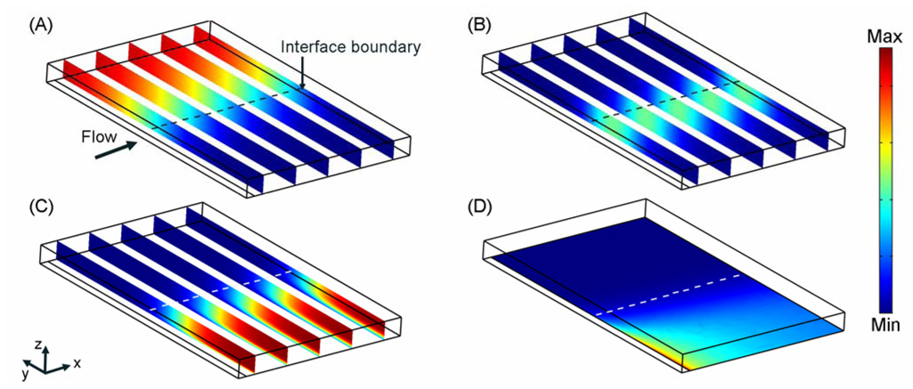
As the solutions flow down the length of the channel, the antibody and analyte solutions mix by diffusion across the fluid interface; antibody and antigen molecules bind to form antibody-analyte complex (Figure 2A–C). The analyte diffuses an order of magnitude faster than the antibody and the antibody-analyte complex. This relative difference in diffusion coefficients results in a bias in the location of the antibody-analyte complex to the side (y-dimension) of the microchannel on which the antibody was introduced (Figure 2B), as the analyte diffuses a greater distance into the antibody stream than vice versa.
Figure 2.
Concentration profiles of species in a typical CGIA. (A)–(C) The concentration profiles for the analyte, antibody-analyte complex, and antibody respectively at time=4.25 minutes where the maximum concentration is 100 nM and minimum concentration is –2.2 × 10⁻⁵ nM. (D) Surface concentration of bound antibody at time=4.25 minutes where the maximum concentration is 1.342 × 10⁻⁸ moles of bound antibody/ m2 and the minimum concentration is −7.334 × 10⁻¹⁴ moles of bound antibody/ m2. The arrow and dashed line indicates the direction of flow and the interface boundary of the microchannel for each image. The initial analyte and antibody concentrations are 100 nM. The modeled geometry is 1 mm (x-dimension) × 1.6 mm (y-dimension) × 0.1 mm (z-dimension).
The immobilized analyte depletes the concentration of antibody near the surface at the beginning of the binding region (Figure 2C). The model result suggests that the concentration of antibody within the SPR imaging detection range (~300 nm from the surface) is extremely low, ensuring that the major contributor to the SPR signal is the surface-bound antibody not antibody free in solution that is in close proximity to the surface. The highest surface concentration of bound antibody (Figure 2D) is located at the leading edge of the binding surface where the antibody present near the microchannel wall binds. Downstream of the beginning of the immobilized analyte surface, the depletion of solution antibody molecules reduces the rate of binding to the surface, resulting in a reduced surface concentration of bound antibody. These results suggest that under the simulated assay conditions the surface reaction is mass-transport limited. Experimental results presented by Nelson et al.1 reveal a similar binding profile in support of this model result.
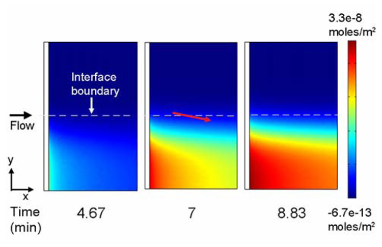
The surface concentration of bound antibody (Figure 3) increases beyond the front of the binding surface (x-dimension) over time. However, the highest surface concentration of antibody remains at the upstream edge of the binding patch. As the solutions flow across the immobilized analyte, the antibody and analyte in solution continue to mix by diffusion and bind to each other to generate antibody-analyte complex. The difference in diffusivities of the antigen and the antibody gives rise to an increasing concentration of complex on the side of the channel to which the antibody was introduced, as previously shown in Figure 2B. The position of the complex within the microchannel along the length of the channel (x-dimension) moves towards the side of the channel (y-dimension) to which the antibody was introduced due to diffusive mixing and reaction. The amount of antibody available to bind to the surface is reduced and is reflected in the binding profile as a slight slope in the surface concentration of bound antibody (indicated by the red arrow in Figure 3).
Figure 3.
Surface concentration of bound antibody over time. The solution analyte and antibody concentrations were set to 100 nM. The red arrow indicates the direction of the slope in the binding profile of antibody to the surface due to the continued formation and diffusion of complex above the immobilized analyte. The results present a 1 mm (x-dimension) × 1.6 mm (y-dimension) region of the binding surface located in the center of the 3 mm wide (y-dimension) microchannel.
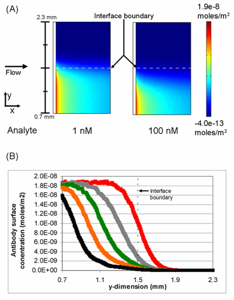
A critical element in the development of this assay is the establishment of a quantitative analysis method. Simulations explored the influence of analyte concentration on the binding of the antibody to immobilized analyte (Figure 4). As shown in Figure 4, for a given antibody concentration the analyte concentration modulates spatial distribution of the concentration gradient of antibody-analyte complex within the microchannel. At higher analyte concentrations, more antibody-analyte complex is formed thereby reducing the concentration of antibody with binding sites available to react with the immobilized analyte.
Figure 4.
Influence of the concentration of analyte on the surface concentration of antibody. (A) Comparison of the surface binding profiles of antibody when the analyte concentration is 1 nM and 100 nM. The black bar at the left indicates the actual y-dimension distance within the microchannel. (B) The surface concentration of antibody as a function of position in the y-dimension at the leading edge of the binding surface. The analyte concentrations plotted are 0 (+), 100 (+), 250(+), 500 (+), and 1000 (+) nM.The concentration of antibody is 100 nM and t=4.67 minutes.
The analyte concentration also modulates the location of the antibody-analyte complex within the microchannel. Relatively higher analyte concentrations increase diffusional transport of the analyte into the antibody stream where it reacts to form antibody-analyte complex. This shifts the location on the surface to which antibody with available binding sites can react with the immobilized analyte.
Figure 4A illustrates this shift in the position on the surface where antibody is available to bind to immobilized analyte. When the analyte concentration is 1 nM and the antibody concentration is 100 nM, very little antibody-analyte complex is formed at the fluidic interface. The majority of antibody in solution is available to bind to the surface. Therefore, antibody is available to bind to the surface near the interface boundary. When the analyte concentration is 100 nM, a significant amount of complex is formed at the fluidic interface and the location on the surface where free antibody can bind shifts away from the interface boundary (y-dimension).
A range of analyte concentrations (1 nM to 1000 nM) was simulated to further explore the influence of analyte on the surface binding profile. The graph in Figure 4B plots the surface concentration of bound antibody at the leading edge of the immobilized analyte patch as a function of the width (y-dimension) of the microchannel. The results indicate that there is a significant shift away from the interface boundary in the binding profile of the antibody with increasing analyte concentration.
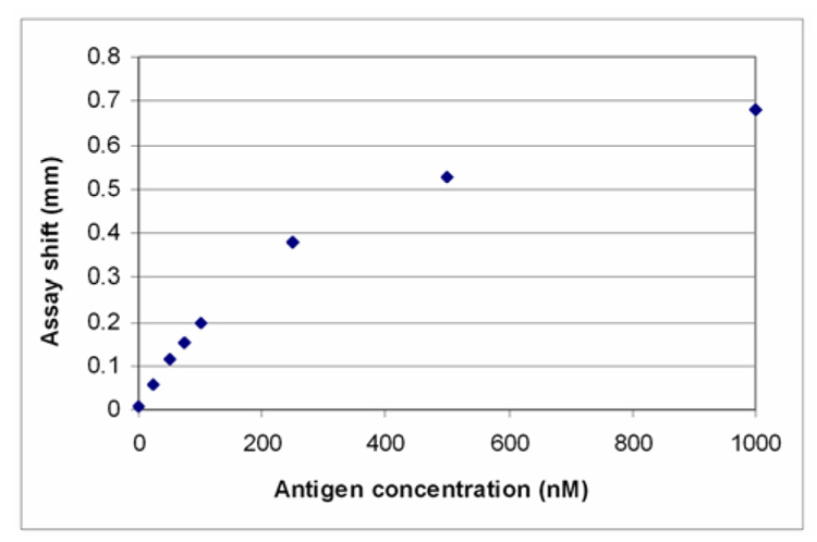
This assay shift, defined as the distance from the interface “boundary” at which 50% of maximal surface concentration of bound antibody occurs, may be used to quantify the total concentration of analyte in solution. In Figure 5, the assay shift is plotted as a function of the analyte concentration. The simulation results indicate that there is a linear relationship between the assay shift and analyte concentration at low analyte concentrations (1 nM – 100 nM). The influence of analyte concentration on assay shift was also measured experimentally by Nelson et al.1 The experimental and model results correlate extremely well indicating that the model accurately captures the relevant experimental parameters.
Figure 5.
Assay shift dependence on analyte concentration. The assay shift is for an antibody surface concentration that is half the maximal surface concentration at that time point (0.9 × 10⁻⁸ moles/m2). The concentration of antibody is 100 nM and t=4.67 minutes.
Given the similarity between the model and experimental results, measuring the assay shift may represent a viable method for quantifying the analyte concentration. A plot similar to Figure 5 would be used to calibrate an instrument’s response. The position at which a given surface concentration of antibody occurs would then be used to determine the analyte’s concentration in a sample. A major benefit of this type of analysis is that it is rapid and does not require extensive calculations or transformation of the data.
An important consideration in the development of a sensitive assay is the interaction time of the antibody and analyte upstream of the antibody binding surface. Longer interaction times will generate larger assay shifts and a more sensitive assay. Therefore, for the CGIA, there is a direct tradeoff between an improvement in sensitivity and the time to complete the assay; this tradeoff can be readily explored using this computational model.
It should be noted that the model presented in this work assumed that the antibody was monovalent, rather than bivalent, due to computational constraints. An IgG molecule with one bound analyte (defined as the complex in the model) can in theory bind to the surface. Therefore, the model underestimates the amount of antibody available to bind to the surface and gives only a semi-quantitative understanding of the experimental results. However, with the current assumptions, the experimental and model results show strong agreement, suggesting that this simplifying assumption does not eliminate the validity of the model. With increased computational resources, bivalency may be incorporated in the 3D model in future work.
The results for the finite element models presented above exhibit some numerical noise given the complex nature of the model. In particular, some of the results indicate that slightly negative concentrations of species (0.002% of the magnitude of the maximum concentration of 100 nM) are present in the microchannel. This non-physical result occurs in a relatively small portion of the model (<<5%) and arises in regions where the species is unlikely to occur – for example the antibody concentration on the side of the channel to which analyte – not antibody – was introduced. Therefore, these negative concentrations do not detract from the validity of the model results.
The noise and the negative concentrations can be attributed to several factors including (1) a mesh which is not dense enough to generate a smooth data set and (2) discontinuities at the initial conditions which would include surface concentrations and solution concentrations which are zero at time = 0. Given the nature of the assay and the computational limitations, the noise in the data and the negative concentrations could not be completely eliminated.
Conclusions
A computational model has been presented that describes a novel surface-based immunoassay – the CGIA – that relies on the inter-diffusion and reaction of antibody and analyte and the binding of an antibody to a surface to quantify the concentration of analyte in a sample. The model data give insight into the underlying transport and reaction mechanisms in the assay and supports a quantitative analysis method directly related to the key feature of this method, namely a diffusion-generated spatial concentration gradient.
Given the large parameter space for this assay (such as flow rate, antibody concentration, microchannel dimensions, type of analyte, range of the medically relevant analyte concentrations, and assay time), the experimental optimization of the performance of this assay would be time-consuming and costly. This computational model, which shows strong agreement with experimental results, can serve as a powerful assay optimization tool. For example, the model may also be used to explore the possibility of using Fab fragments instead of whole antibody molecules, or the practicality of detecting large analytes such as proteins instead of small molecules.
Supplementary Material
A five-page listing of the governing equations and the initial conditions and boundary conditions of the model is available as Supporting Information. Current ordering information is found on any masthead page.
ACKNOWLEDGMENT
This work was completed under the support of a NIH training grant (1 T32 GM065098-01A1) and a cooperative research agreement supported by the NIDCR (Grant No. 1UO1 DE14971-01). The authors would like to thank Kenneth Hawkins for helpful discussions with regard to antibody kinetics, and Dr. Elena Garcia for assistance with models.
REFERENCES
- 1.Nelson K, Foley J, Yager P. Anal. Chem. in press. [Google Scholar]
- 2.Weigl BH, Yager P. Science. 1999;283:346–347. [Google Scholar]
- 3.Kamholz AE, Weigl BH, Finlayson BA, Yager P. Anal. Chem. 1999;71:5340–5347. doi: 10.1021/ac990504j. [DOI] [PubMed] [Google Scholar]
- 4.Yager P, Edwards T, Fu E, Helton K, Nelson K, Tam MR, Weigl BH. Nature Insight. 2006;442:412–418. doi: 10.1038/nature05064. [DOI] [PubMed] [Google Scholar]
- 5.Stone HA, Kim S. AIChE J. 2001;47:1250–1254. [Google Scholar]
- 6.Figeys D, Pinto D. Anal. Chem. 2000;72:330A–335A. doi: 10.1021/ac002800y. [DOI] [PubMed] [Google Scholar]
- 7.Gobi KV, Tanaka H, Shoyama Y, Miura N. Biosens. Bioelectron. 2004;20:350–357. doi: 10.1016/j.bios.2004.02.003. [DOI] [PubMed] [Google Scholar]
- 8.Whelan JP, Kusterbeck AW, Wemhoff GA, Bredehorst R, Ligler FS. Anal. Chem. 1993;65:3561–3565. [Google Scholar]
- 9.Kusterbeck AW, Wemhoff GA, Charles PT, Yeager DA, Bredehorst R, Vogel CW, Ligler FS. J. Immunol. Methods. 1990;135:191–197. doi: 10.1016/0022-1759(90)90272-w. [DOI] [PubMed] [Google Scholar]
- 10.Taitt CR, Golden JP, Shubin YS, Shriver-Lake LC, Sapsford KE, Rasooly A, Ligler FS. Microbial Ecology. 2004;47:175–185. doi: 10.1007/s00248-003-1011-1. [DOI] [PubMed] [Google Scholar]
- 11.Cesaro-Tadic S, Dernick G, Juncker D, Buurman G, Kropshofer H, Michel B, Fattinger C, Delamarche E. Lab Chip. 2004;4:563–569. doi: 10.1039/b408964b. [DOI] [PubMed] [Google Scholar]
- 12.Bernard A, Michel B, Delamarche E. Anal. Chem. 2001;73:8–12. doi: 10.1021/ac0008845. [DOI] [PubMed] [Google Scholar]
- 13.Dodge A, Fluri K, Verpoorte E, de Rooij NF. Anal. Chem. 2001;73:3400–3409. doi: 10.1021/ac0015366. [DOI] [PubMed] [Google Scholar]
- 14.Daly SJ, Keating GJ, Dillon PP, Manning BM, O'Kennedy R, Lee HA, Morgan MRA. J. Agric. and Food Chem. 2000;48:5097–5104. doi: 10.1021/jf9911693. [DOI] [PubMed] [Google Scholar]
- 15.Ligler FS, Taitt CR, Shriver-Lake LC, Sapsford KE, Shubin Y, Golden JP. Anal. and Bioanal. Chem. 2003;377:469–477. doi: 10.1007/s00216-003-1992-0. [DOI] [PubMed] [Google Scholar]
- 16.Juncker D, Michel B, Hunziker P, Delamarche E. Biosens. Bioelectron. 2004;19:1193–1202. doi: 10.1016/j.bios.2003.11.003. [DOI] [PubMed] [Google Scholar]
- 17.Yu F, Persson B, Lofas S, Knoll W. Anal. Chem. 2004;76:6765–6770. doi: 10.1021/ac048937w. [DOI] [PubMed] [Google Scholar]
- 18.Vareiro MLM, Liu J, Knoll W, Zak K, Williams D, Jenkins ATA. Anal. Chem. 2005;77:2426–2431. doi: 10.1021/ac0482460. [DOI] [PubMed] [Google Scholar]
- 19.Hatch A, Kamholz AE, Hawkins KR, Munson MS, Schilling EA, Weigl BH, Yager P. Nat. Biotechnol. 2001;19:461–465. doi: 10.1038/88135. [DOI] [PubMed] [Google Scholar]
- 20.Hatch A, Garcia E, Yager P. Proc. IEEE; 2004. pp. 126–139. [Google Scholar]
- 21.Weigl BYP, Kamholz A, Hatch A. U.S. Patent #574797. Microscale diffusion immunoassay. 2000
- 22.Davies J. Surface Analytical Techniques for Probing Biomaterial Processes. 1st ed. Boca Raton, FL: CRC Press; 1996. [Google Scholar]
- 23.Fu E, Foley J, Yager P. Rev. Sci. Instrum. 2003;74:3182–3184. [Google Scholar]
- 24.Fu E, Chinowsky T, Foley J, Weinstein J, Yager P. Rev. Sci. Instrum. 2004;75:2300–2304. [Google Scholar]
- 25.Bird RB, Stewart WE, Lightfoot EN. Transport Phenomena. 2nd ed. New York, NY: Wiley Publishing; 2002. [Google Scholar]
- 26.COMSOL. FEMLAB Transport Phenomena Course. 2003:38–48. [Google Scholar]
- 27.Sarma VR, Silverto EW, Davies DR, Terry WD. J. of Biol. Chem. 1971;246:3753. [PubMed] [Google Scholar]
- 28.Peters T. All About Albumin: Biochemistry, Genetics, and Medical Applications. San Diego: Academic Press; 1996. [Google Scholar]
- 29.Holde KEV. Physical Biochemistry. 2nd ed. Englewood Cliffs, NJ: Prentice Hall; 1985. [Google Scholar]
- 30.Stenberg M, Nygren H. Journal of Immunological Methods. 1988;113:3–15. doi: 10.1016/0022-1759(88)90376-6. [DOI] [PubMed] [Google Scholar]
- 31.Griffiths AD. EMBO J. 1993;12:725–734. doi: 10.1002/j.1460-2075.1993.tb05706.x. [DOI] [PMC free article] [PubMed] [Google Scholar]
- 32.Kaufman EN, Jain RK. Biophys. J. 1991;60:596–610. doi: 10.1016/S0006-3495(91)82089-6. [DOI] [PMC free article] [PubMed] [Google Scholar]
- 33.Polzius R, Diessel E, Bier FF, Bilitewski U. Anal. Biochem. 1997;248:269–276. doi: 10.1006/abio.1997.2105. [DOI] [PubMed] [Google Scholar]
Associated Data
This section collects any data citations, data availability statements, or supplementary materials included in this article.
Supplementary Materials
A five-page listing of the governing equations and the initial conditions and boundary conditions of the model is available as Supporting Information. Current ordering information is found on any masthead page.


