Abstract
Branched DNA motifs can be designed to assume a variety of shapes and structures. These structures can be characterized by numerous solution techniques; the structures also can be inferred from atomic force microscopy of two-dimensional periodic arrays that the motifs form via cohesive interactions. Examples of these motifs are the DNA parallelogram, the bulged-junction DNA triangle, and the three-dimensional-double crossover (3D-DX) DNA triangle. The ability of these motifs to withstand stresses without changing geometrical structure is clearly of interest if the motif is to be used in nanomechanical devices or to organize other large chemical species. Metallic nanoparticles can be attached to DNA motifs, and the arrangement of these particles can be established by transmission electron microscopy. We have attached 5 nm or 10 nm gold nanoparticles to every vertex of DNA parallelograms, to two or three vertices of 3D-DX DNA triangle motifs, and to every vertex of bulged-junction DNA triangles. We demonstrate by transmission electron microscopy that the DNA parallelogram motif and the bulged-junction DNA triangle are deformed by the presence of the gold nanoparticles, whereas the structure of the 3D-DX DNA triangle motif appears to be minimally distorted. This method provides a way to estimate the robustness and potential utility of the many new DNA motifs that are becoming available.
INTRODUCTION
Branched DNA motifs have been used to design objects (1), periodic arrays (2), and nanomechanical devices (3,4). It is important to be able to characterize the structural integrity of DNA motifs and to know whether they can withstand various perturbations when they are used as the basis for scaffolding other chemical species (5,6), as components in complex nanomechanical systems (7), as substrates for biochemical studies (8), or as measurement tools in molecular biophysics (9,10). We have shown that the double crossover (DX) motif has a persistence length larger than that of simple double helical DNA (11). The DX motif consists of two double helices with parallel helix axes that are linked by strands that crossover between the helices. A number of motifs have been designed using helices with parallel axes (e.g., 12–15). However, there are a number of other motifs that do not have this property, and it would be useful to have an assay for their relative robustness.
The DNA parallelogram is a motif that consists of four Holliday-like branched junctions (16). The Holliday junction is a four-arm DNA branch, whose arms distribute themselves into two double-helical domains twisted from each other by ∼60° (16,17). Ligation-closure experiments (18) and time-resolved fluorescence resonance energy transfer measurements (19) have indicated that the individual Holliday junction is somewhat plastic about the point connecting the two domains. Nevertheless, despite the flexible nature of the individual Holliday junction, the combination of four such junctions leads to a parallelogram motif that forms periodic one- and two-dimensional arrays with tunable cavities (16). Thus, the parallelogram appears to be less flexible than the individual Holliday junction. The parallelogram arrays have been used to measure the angles between the domains of four-arm junctions in systems of biochemical interest (9,10).
It is valuable to establish the relative structural robustness of the individual motif as well as the periodic structure. For example, if the motif is to be employed as a component in a nanomechanical device, it is very important that the motif be robust and not readily distorted. Indeed, the development of the first robust nucleic acid nanomechanical device (3) took 12 years, awaiting the development of the stiff DX motif; it was not possible to get an unambiguous signal to the fluorescence resonance energy transfer experiments used there without a robust motif (20,21). The measurement of DNA distortion by proteins was also dependent on the robustness of the TX motif (22). An atomic force microscopy approach to estimating the robustness of DNA tetrahedra has been presented by Turberfield and his colleagues (23).
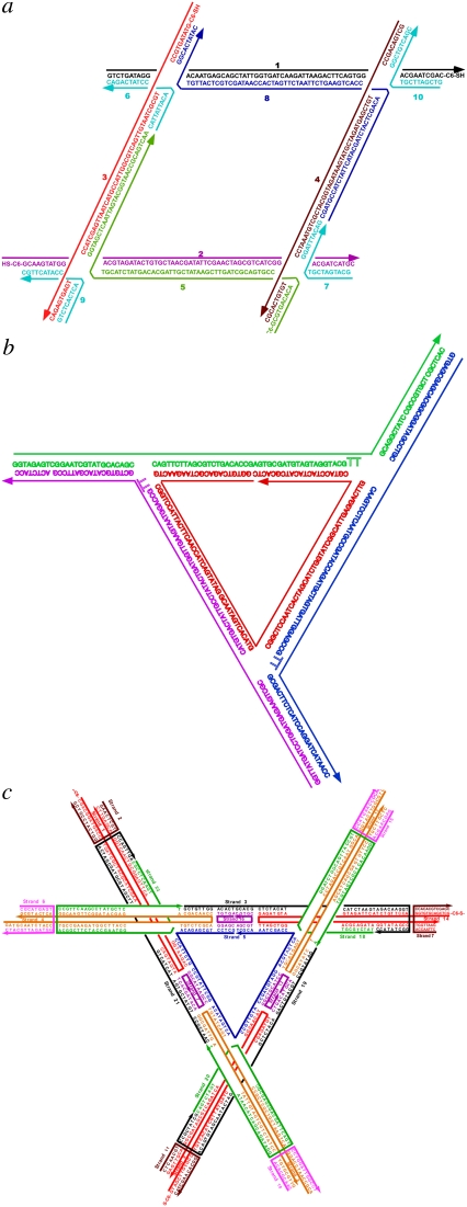
For the parallelogram, we ask whether the combination of four fused Holliday junctions into a parallelogram produces a structure that is reliable in the presence of perturbations, even though the individual Holliday junction is flexible and the lattice appears to be inflexible. We do this by attaching metallic gold nanoparticles to every vertex of a parallelogram (structure and sequence in Fig. 1 a); this is done by incorporating into the parallelogram a strand to which a nanoparticle is attached. We use a combination of 5 nm and 10 nm particles; our assay is the ability of the parallelogram to demonstrate a constant shape (preferably similar to the designed shape), as revealed by the pattern of nanoparticles seen in the transmission electron microscope (TEM).
FIGURE 1.
The sequences of the molecules used here. (a) The parallelogram. (b) The bulged-junction triangle. (c) The DX triangle. “C6-S-” indicates the particle site of attachment.
As baselines for comparison with the parallelogram, we use a bulged-junction DNA triangle, known to be somewhat flexible (structure and sequence in Fig. 1 b) (24), and the three-dimensional (3D)-DX triangle (structure and sequence in Fig. 1 c), whose behavior suggests that it is quite robust (5,25,26). The bulged-junction DNA triangle contains three-arm junctions at its corners, but its design includes 12 extra backbone bonds (from two deoxythymidine residues) at the junctions, enabling two of its arms to stack upon one another. Its helix axes are designed to be coplanar. By contrast, the 3D-DX triangle incorporates four-arm junctions at the sites where its DX edges intersect. The orientations of the three edges are not coplanar but have an over-and-under relationship that leads to the directions of its helix axes spanning three-space. The use of these baseline motifs controls for perturbations caused by the deposition procedure and for the effect of possible basepair disruption in the vicinity of the nanoparticles.
EXPERIMENTAL METHODS
The sequences of parallelogram, the bulged-junction triangle, and the 3D-DX triangle DNA molecule used here were designed with the program SEQUIN (27). All oligonucleotides were synthesized by conventional phosphoramidite procedures and were purified by denaturing polyacrylamide gel electrophoresis. All three motifs were constructed by annealing stoichiometric mixtures of the strands (estimated by OD260) to a concentration of 0.5 μM in a buffer solution containing 10 mM HEPES, 1 mM EDTA, 3.5 mM MgCl2, and 500 mM NaCl and cooling from 75°C to room temperature.
Gold colloids with mean diameters of 5 and 10 nm were either purchased (Ted Pella, Redding, CA) or synthesized by the citrate/tannic acid method. Citrate-stabilized gold colloids were subsequently passivated with a monolayer of anionic phosphine molecules as described elsewhere (28) to avoid nonspecific binding of nucleic acids and overcome the tendency toward self-agglomerization and precipitation. The colloidal solution was concentrated up to the micromolar range after phosphine coating. DNA/Au conjugates were prepared by mixing gold nanoparticles with 5′ or 3′ end-thiolated (-SH) single-stranded DNA with a mole ratio of 3:1 and incubated for 2 h in HEPES buffer (10 mM HEPES, 1 mM EDTA, and 50 mM NaCl). The method used for isolating conjugates containing singly and multiply functionalized gold nanoparticles from unreacted starting materials is gel electrophoresis (2.5% agarose gel at 5 V/cm, HEPES buffer same as above), followed by recovery of the appropriate band. We collected ∼100 μL of a red-colored solution and then diluted it to a final volume of 500 μL in a solution containing 100 mM Na+. After further incubation for 5 h, the volume was slowly reduced to 100 μL by vacuum centrifugation at room temperature. This process produces a gradual increase in ionic strength, which in turn leads to much more stable DNA/Au conjugates.
The designed gold tetramers interconnected by parallelogram DNA molecules and trimers and dimers on 3D-DX, and bulged-junction triangle DNA molecules were formed by slowly annealing a mixture of highly purified Au/DNA conjugates and other component DNA strands from 75°C to room temperature by placing a 2 L beaker in an insulated Styrofoam box for at least 24 h. The final reaction volume was 50 μl and the concentration of each oligonucleotide was 0.5 μM, with the exception of the Au/DNA conjugates, which were present at 0.8 μM in a buffer solution containing 10 mM HEPES, 1 mM EDTA, 3.5 mM MgCl2, and 500 mM NaCl. A low initial temperature was used to ensure the stability of Au/DNA conjugate. After this incubation, the parallelogram and triangle DNA/Au conjugates were purified and collected following the same procedure as above.
TEM imaging was performed using a Philips CM-10 instrument (Philips, Eindhoven, The Netherlands) operated at 80 kV. The particle sample was prepared on 400 mesh Formvar-coated copper grids by dropping a 5 μL sample solution on grids and then wicking off excess solution by using filter paper after 30 s. All grids were dried in a desiccator at least overnight.
RESULTS
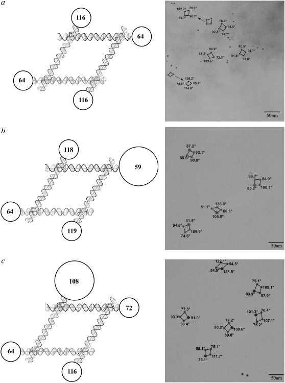
Fig. 2 illustrates three of the experiments that we have conducted with DNA parallelograms. The left side of each panel shows a schematic diagram of the molecule plus nanoparticles, and the right side shows representative TEM pictures obtained from the same species. The parallelogram lacking nanoparticles has been shown previously to have an acute angle that is ∼60°, in good agreement with other estimates for the angles flanking a Holliday junction (16). The angles in the circles are estimates of the angles expected between the centers of the nanoparticles, owing to their placement. The sequence flanking the branched junction determines which pairs of arms stack to form the linear domains (29), and the relationships of the strands participating in the acute and obtuse angles are well established (9,12,30). Thus, we refer to the “acute” or “obtuse” angles of a parallelogram based on the well-known particle-free structure of the four-arm branched junction, regardless of the geometry of the parallelogram observed here. Fig. 2 a illustrates a molecule to which 5 nm gold particles have been attached on all four corners. As in all the experiments shown, two are attached to the lower horizontal domains, and two are attached to the upper domains. It is clear that a significant level of distortion from an ideal 60°–120° parallelogram is present.
FIGURE 2.
DNA parallelograms with gold nanoparticles. The expected angles between the edges of the parallelograms are shown in the circles in the schematics at left and are indicated on the TEM pictures at right. The circles are scaled to indicate nanoparticle size. (a) Four 5 nm gold nanoparticles. For clarity, some angles are displaced in the TEM picture. (b) Three 5 nm nanoparticles and one 10 nm nanoparticle near an acute angle. Note the second parallelogram from the bottom, where the 10 nm particle flanks an obtuse angle. (c) Three 5 nm nanoparticles and one 10 nm nanoparticle near an obtuse angle. Note the bottom image, where the 10 nm particle flanks an acute angle.
Fig. 2, b and c illustrates an asymmetric experiment where a single 10 nm particle and three 5 nm particles have been attached to the parallelogram. In Fig. 2 b, the 10 nm particle has been designed to abut the angle that is normally acute, and in Fig. 2 c it has been designed to abut the angle that is normally obtuse. The images in Fig. 2 b show acute angles near the 10 nm particle ranging from 82° to 87°, but in the second image from the bottom, the acute angle is 106°. The complementary system in Fig. 2 c shows obtuse angles ranging from 91° to 129°, but two images (the one on the bottom and the one on the upper right) show “obtuse” angles of 75° and 84°, respectively.
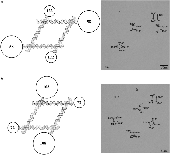
Fig. 3 shows experiments where two 10 nm particles have been attached symmetrically to the molecules. Fig. 3 a illustrates the case where the 10 nm particles are adjacent to the nominally acute angles. The lower left shows an image that is almost exactly the molecule that was designed, but the other three images show acute angles that range from 82° to 95°. Fig. 3 b shows the complementary experiment, where the 10 nm particles are attached to the nominally obtuse angles. In the top four images, the obtuse angles range from 90° to 111°. The bottom image shows a reversal of the obtuse and acute angles, with the nominally obtuse angles of 63° and 69°. It is unlikely that crossover isomerization (31) has occurred, and it is more likely that the potentially flexible torsion angle between the upper and lower domains has been affected by the presence of the nanoparticles.
FIGURE 3.
DNA parallelograms with two 5 nm particles and two 10 nm particles. The same conventions apply as in Fig. 2. (a) The 10 nm particles flank acute angles. The bottom image is nearly ideal, but the other images are distorted significantly. (b) The 10 nm particles flank obtuse angles. Distortions are seen in several of the parallelograms, most prominently in the bottom image, where the expected distribution is reversed.
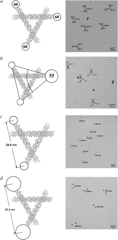
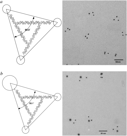
We have examined two different triangular systems as controls. The first is the bulged-junction triangle, which is known to be flexible when constructed from single helical domains (24) although it is much stiffer when built from DX components (26,32). The second system is the robust 3D-DX triangle system (5), which is based on Mao's tensegrity triangle (33). We have performed four experiments, putting 5 nm particles on all three vertices, replacing one 5 nm particle with a 10 nm particle, and putting 5 nm or 10 nm particles on only two vertices, perhaps enabling the asymmetry of the system to distort the triangles. Fig. 4 illustrates these experiments. Fig. 4 a shows the TEM image of a 3D-DX triangle with three 5 nm particles attached to it, one on each vertex. The distortions are very small. The lower triangle on the right has angles of 57° and 63°, which is as far from ideality as is seen here. Fig. 4 b illustrates the results when one of the 5 nm particles is replaced by a 10 nm particle; the deviations from ideality remain small. Fig. 4 c shows the results of decreasing the symmetry of the system further, by adding only two particles to the DNA motif; the expected distances are 28.9 nm, and the observed distances are 28.4 ± 1.2 nm. Fig. 4 d shows the dimer experiment for 10 nm particles. The expected distance is 33.2 nm, and the measured distance is 33.2 ± 0.8 nm. Thus, in contrast to the parallelogram motif, the deviations from the expected structure in the 3D-DX motif are minimal.
FIGURE 4.
3D-DX triangles with two or three particles attached. (a) Three 5 nm particles attached. Note that the triangles are not significantly distorted from ideality. (b) Two 5 nm particles and one 10 nm particle attached. Only minor distortions are seen. (c) Two 5 nm particles attached. This asymmetric distribution of particles produces separations close to the expected values. (d) Two 10 nm particles attached. Even 10 nm particles attached asymmetrically do not produce separations indicative of motif distortion.
Fig. 5 illustrates a further control in the contrast between the robustness of the 3D-DX triangle and the pliability of the parallelogram. One could argue that a triangle, even one with extensions beyond its vertices, is inherently rigid, so why is it surprising that the 3D-DX motif is more robust than the parallelogram? To determine whether the importance of the triangular motif is a factor in the apparent rigidity of the 3D-DX motif, we have examined the bulged-junction triangle (24). Fig. 5 illustrates two experiments performed with this motif: Fig. 5 a shows the structure of representative bulged-junction triangles to which three 5 nm particles have been attached, and Fig. 5 b shows the structure of bulged-junction triangles containing two 5 nm particles and one 10 nm particle. In each image, there is a single three-dot cluster that is close to ideality, and the rest are dramatically distorted. Thus, simply possessing a triangular structure is insufficient to yield a structure that is not readily distorted by the addition of nanoparticles to the perimeter of the motif.
FIGURE 5.
Bulged-junction triangles with three particles attached. (a) Three 5 nm particles. (b) Two 5 nm particles and one 10 nm particle. In each case, a triangle can be seen that is near the expected shape, but most triangles are highly distorted.
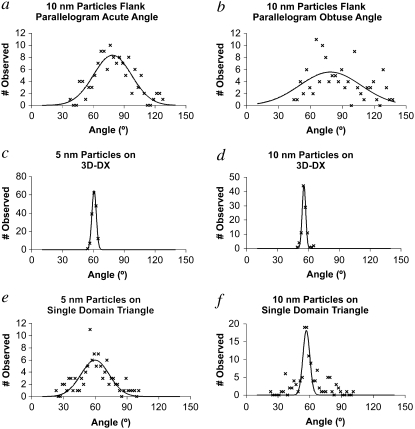
The TEM images in Figs. 2–5 depict only a sampling of our data. We have fit the angular distributions of all the structures visualized with a Gaussian function for a number of the systems examined here, giving us an estimate of the breadth of angles that are seen for key systems. These data are shown in Fig. 6, and the parameters defining the Gaussians are summarized in Table 1. The parallelogram system is shown in Fig. 6, a and b, which describes the parallelograms where a single 10 nm particle is attached next to the acute and obtuse angles, respectively. The full width at half-maxima (FWHMs) of these distributions are very broad (52° and 80°, respectively), in agreement with the qualitative estimate from the images that these angles are poorly defined when stressed by the perturbation introduced by the presence of nanoparticles.
FIGURE 6.
Angular distributions observed and fit by a Gaussian function. The parallelogram distributions (a) and (b) are very broad, as is the distribution of the single domain triangle with three 5 nm particles (e). The distribution of the triangle with a 10 nm particle is narrower but is badly fit by a single Gaussian (f). The 3D-DX distributions are very narrow (c) and (d). The parameters describing the distributions are listed in Table 1.
TABLE 1.
Parameters Used to Fit Angular Distributions
| Acute P | Obtuse P | 5-3D-DX | 10-3D-DX | 5-BJT | 10-BJT | |
|---|---|---|---|---|---|---|
| A | 8.35 ± 0.6 | 5.58 ± 0.8 | 64.4 ± 2.2 | 44.2 ± 3.2 | 5.98 ± 1.4 | 18.15 ± 1.9 |
| X0 | 78.7 ± 1.5 | 78.9 ± 5.3 | 60.8 ± 0.1 | 55.6 ± 0.1 | 59.8 ± 1.4 | 56.8 ± 0.4 |
| W | 26.1 ± 2.1 | 40.7 ± 8.8 | 3.02 ± 0.1 | 2.4 ± 0.2 | 18.9 ± 1.9 | 4.6 ± 0.5 |
Y = A exp −[(X − X0)2/(W)2]. A is the preexponential factor, X0 is the centroid of the distribution, and W SQRT [ln(2)] is the FWHM of the distribution. The units of X0 and W are degrees, and A is a dimensionless number.
By contrast, the 3D-DX motif is robust. Both the system with three 5 nm particles (Fig. 6 c) and the one with two 5 nm particles and one 10 nm particle (Fig. 6 d) show narrow distributions (6° and 5°, respectively). The bulged-junction triangle is intermediate, showing that some benefit is to be derived from triangularity and a different type of branched junction but not enough to produce a robust motif. Fig. 6 e shows the distribution of angles seen for three 5 nm particles attached to a bulged-junction triangle. The centroid of this distribution is approximately where we expect it (Table 1), but the width of the distribution is ∼38°. The inclusion of a single 10 nm pattern along with two 5 nm particles (Fig. 6 f) surprisingly seems to narrow the distribution (9°), but it is also clear that the distribution is not fit well by a single Gaussian function.
DISCUSSION
We have demonstrated that it is possible to use the attachment of metallic nanoparticles to estimate the robustness of a DNA motif. We have characterized the parallelogram and 3D-DX triangle motifs here, both of which have four-arm junctions at their vertices; we have also characterized the bulged-junction triangle, whose vertices consist of bulged three-arm branched junctions. It is clear that the presence of nanoparticles has a minimal effect on the 3D-DX triangles and a greater impact on the bulged-junction triangles, known to be less robust; the vertex angles of the parallelograms are susceptible to major distortions, even though they are capable of forming well-defined and uniform two-dimensional arrays when unperturbed. We do not know the specific causes of the distortions, except that it is clear from the controls that they result from the presence of nanoparticles. Nevertheless, it is easy to rank the motifs in order of robustness: the 3D-DX triangle is clearly a more robust motif than the bulged-junction triangle, which is in turn more robust than the parallelogram if the goal is to use the motifs in situations where they will be subject to stresses.
Thus, we have devised a method to estimate the structural integrity of DNA motifs. Early work in the field showed that the most flexible points in complex DNA motifs are at the branch points (18,19). Here, we have shown that a perturbation can cause the flexibility of these points to lead to a distribution of structures. We expect this method to have broad applicability in assaying the value of future systems that will be developed in structural DNA nanotechnology.
Acknowledgments
This research was supported by grants to N.C.S.: GM-29554 from National Institute of General Medical Sciences, grants DMI-0210844, EIA-0086015, CCF-0523290, CCF-0726378, and CTS-0548774, CTS-0608889 from the National Science Foundation, 48681-EL and MURI W911NF-07-1-0439 from Army Research Office, DE-FG02-06ER64281 from the Department of Energy (DOE) (subcontract from the Research Foundation of State University of New York), a grant from the W.M. Keck Foundation to N.C.S. and contract No. DE-AC02-05CH11231 from the Materials Science Division of DOE and Defense Advanced Research Projects Agency/Air Force Office of Scientific Research Defense University Research Initiative on Nanotechnology program grant No. F49620-01-1-0474 under subcontract No. 066995 through the University of Southern California to A.P.A. W.B.S. was supported by the DOE Office of Science and Office of Basic Energy Sciences under contract No. DE-AC02-98CH10866.
Editor: David P. Millar.
References
- 1.Chen, J., and N. C. Seeman. 1991. The synthesis from DNA of a molecule with the connectivity of a cube. Nature. 350:631–633. [DOI] [PubMed] [Google Scholar]
- 2.Winfree, E., F. Liu, L. A. Wenzler, and N. C. Seeman. 1998. Design and self-assembly of two-dimensional DNA crystals. Nature. 394:539–544. [DOI] [PubMed] [Google Scholar]
- 3.Mao, C., W. Sun, Z. Shen, and N. C. Seeman. 1999. A DNA nanomechanical device based on the B-Z transition. Nature. 397:144–146. [DOI] [PubMed] [Google Scholar]
- 4.Yan, H., X. Zhang, Z. Shen, and N. C. Seeman. 2002. A robust DNA mechanical device controlled by hybridization topology. Nature. 415:62–65. [DOI] [PubMed] [Google Scholar]
- 5.Zheng, J., P. E. Constantinou, C. Micheel, A. P. Alivisatos, R. A. Kiehl, and N. C. Seeman. 2006. 2D nanoparticle arrays show the organizational power of robust DNA motif. Nano Lett. 6:1502–1504. [DOI] [PMC free article] [PubMed] [Google Scholar]
- 6.Aldaye, F. A., and H. F. Sleiman. 2007. Dynamic DNA templates for discrete gold nanoparticle assemblies: control of geometry, modularity, write/erase and structural switching. J. Am. Chem. Soc. 129:4130–4131. [DOI] [PubMed] [Google Scholar]
- 7.Liao, S., and N. C. Seeman. 2004. Translation of DNA signals into polymer assembly instructions. Science. 306:2072–2074. [DOI] [PMC free article] [PubMed] [Google Scholar]
- 8.Liao, S., C. Mao, J. J. Birktoft, S. Shuman, and N. C. Seeman. 2004. Resolution of undistorted symmetric immobile DNA junctions by vaccinia topoisomerase I. Biochemistry. 43:1520–1531. [DOI] [PubMed] [Google Scholar]
- 9.Sha, R., F. Liu, D. P. Millar, and N. C. Seeman. 2000. Atomic force microscopy of parallel DNA branched junction arrays. Chem. Biol. 7:743–751. [DOI] [PubMed] [Google Scholar]
- 10.Sha, R., F. Liu, and N. C. Seeman. 2002. Atomic force measurement of the interdomain angle in symmetric Holliday junctions. Biochemistry. 41:5950–5955. [DOI] [PubMed] [Google Scholar]
- 11.Sa-Ardyen, P., A. V. Vologodskii, and N. C. Seeman. 2003. The flexibility of DNA double crossover molecules. Biophys. J. 84:3829–3837. [DOI] [PMC free article] [PubMed] [Google Scholar]
- 12.LaBean, T. H., H. Yan, J. Kopatsch, F. Liu, E. Winfree, J. H. Reif, and N. C. Seeman. 2000. The construction, analysis, ligation and self-assembly of DNA triple crossover complexes. J. Am. Chem. Soc. 122:1848–1860. [Google Scholar]
- 13.Mathieu, F., S. Liao, C. Mao, J. Kopatsch, T. Wang, and N. C. Seeman. 2005. Six-helix bundles designed from DNA. Nano Lett. 5:661–665. [DOI] [PMC free article] [PubMed] [Google Scholar]
- 14.Yan, H., S. H. Park, G. Finklestein, J. H. Reif, and T. H. LaBean. 2003. DNA-templated self-assembly of protein arrays and highly conductive nanowires. Science. 301:1882–1884. [DOI] [PubMed] [Google Scholar]
- 15.Ke, Y., Y. Liu, J. Zhang, and H. Yan. 2006. A study of DNA tube formation mechanisms using 4-, 8-, and 12-helix DNA nanostructures. J. Am. Chem. Soc. 128:4414–4421. [DOI] [PubMed] [Google Scholar]
- 16.Mao, C., W. Sun, and N. C. Seeman. 1999. Designed two-dimensional DNA Holliday junction arrays visualized by atomic force microscopy. J. Am. Chem. Soc. 121:5437–5443. [Google Scholar]
- 17.Lilley, D. M. J., and R. M. Clegg. 1993. The structure of the 4-way junction in DNA. Annu. Rev. Biophys. Biomol. Struct. 22:299–328. [DOI] [PubMed] [Google Scholar]
- 18.Petrillo, M. L., C. J. Newton, R. P. Cunningham, R.-I. Ma, N. R. Kallenbach, and N. C. Seeman. 1988. The ligation and flexibility of 4-arm DNA junctions. Biopolymers. 27:1337–1352. [DOI] [PubMed] [Google Scholar]
- 19.Eis, P. S., and D. P. Millar. 1993. Conformational distributions of a four-way DNA junction revealed by time-resolved fluorescence resonance energy transfer. Biochemistry. 32:13852–13860. [DOI] [PubMed] [Google Scholar]
- 20.Fu, T.-J., and N. C. Seeman. 1993. DNA double crossover structures. Biochemistry. 32:3211–3220. [DOI] [PubMed] [Google Scholar]
- 21.Li, X., X. Yang, J. Qi, and N. C. Seeman. 1996. Antiparallel DNA double crossover molecules as components for nanoconstruction. J. Am. Chem. Soc. 118:6131–6140. [Google Scholar]
- 22.Shen, W. Q., M. Bruist, S. Goodman, and N. C. Seeman. 2004. A nanomechanical device for measuring the excess binding energy of proteins that distort DNA. Angew. Chem. Int. Ed. 116:4854–4856. [DOI] [PubMed] [Google Scholar]
- 23.Goodman, R. P., I. A. T. Schaap, C. F. Tarden, T. M. Erben, R. M. Berry, C. F. Schmidt, and A. J. Turberfield. 2005. Rapid chiral assembly of tetrahedral building blocks for molecular nanofabrication. Science. 310:1661–1665. [DOI] [PubMed] [Google Scholar]
- 24.Qi, J., X. Li, X. Yang, and N. C. Seeman. 1996. The ligation of triangles built from bulged three-arm DNA branched junctions. J. Am. Chem. Soc. 118:6121–6130. [Google Scholar]
- 25.Carbone, A., C. Mao, P. E. Constantinou, B. Ding, J. Kopatsch, W. B. Sherman, and N. C. Seeman. 2004. 3D fractal DNA assembly from coding, geometry and protection. Nat. Comput. 3:235–252. [Google Scholar]
- 26.Constantinou, P. E., T. Wang, J. Kopatsch, L. B. Israel, X. Zhang, B. Ding, W. B. Sherman, X. Wang, J. Zheng, R. Sha, and N. C. Seeman. 2006. Double cohesion in structural DNA nanotechnology. Org. Biomol. Chem. 4:3414–3419. [DOI] [PMC free article] [PubMed] [Google Scholar]
- 27.Seeman, N. C. 1990. De novo design of sequences for nucleic acid structure engineering. J. Biomol. Struct. Dyn. 8:573–581. [DOI] [PubMed] [Google Scholar]
- 28.Zanchet, D., C. Micheel, W. Parak, and A. P. Alivisatos. 2002. Electrophoretic and structural studies of DNA-directed Au nanoparticle grouping. J. Phys. Chem. B. 106:11758–11763. [Google Scholar]
- 29.Chen, J.-H., M. E. A. Churchill, T. D. Tullius, N. R. Kallenbach, and N. C. Seeman. 1988. Construction and analysis of mono-mobile DNA junctions. Biochemistry. 27:6032–6038. [DOI] [PubMed] [Google Scholar]
- 30.Seeman, N. C., and N. R. Kallenbach. 1994. DNA branched junctions. Annu. Rev. Biophys. Biomol. Struct. 23:53–86. [DOI] [PubMed] [Google Scholar]
- 31.Li, X., H. Wang, and N. C. Seeman. 1997. Direct evidence for Holliday junction crossover isomerization. Biochemistry. 36:4240–4247. [DOI] [PubMed] [Google Scholar]
- 32.Ding, B., R. Sha, and N. C. Seeman. 2004. 2D DNA crystals from double crossover cohesion. J. Am. Chem. Soc. 126:10230–10231. [DOI] [PubMed] [Google Scholar]
- 33.Liu, D., M. Wang, Z. Deng, R. Walulu, and C. Mao. 2004. Tensegrity: construction of rigid DNA triangles with flexible four-arm DNA Junctions. J. Am. Chem. Soc. 126:2324–2325. [DOI] [PubMed] [Google Scholar]


