

Abstract
Several new image-guidance tools and devices are being prototyped, investigated, and compared. These tools are introduced and include prototype software for image registration and fusion, thermal modeling, electromagnetic tracking, semiautomated robotic needle guidance, and multimodality imaging. The integration of treatment planning with computed tomography robot systems or electromagnetic needle-tip tracking allows for seamless, iterative, “see-and-treat,” patient-specific tumor ablation. Such automation, navigation, and visualization tools could eventually optimize radiofrequency ablation and other needle-based ablation procedures and decrease variability among operators, thus facilitating the translation of novel image-guided therapies. Much of this new technology is in use or will be available to the interventional radiologist in the near future, and this brief introduction will hopefully encourage research in this emerging area.
The latest diagnostic imaging tools, navigation technology, and novel image-processing software have not yet been fully applied in the interventional radiology suite during radiofrequency ablation (RFA). Physicians often use one imaging modality at a time with insufficient feedback during the intervention and often without any options even remotely resembling simulation or treatment planning. Both ultrasound (US) and computed tomography (CT) suffer from lack of surrogate markers of treatment effect. Although US imaging gives real-time feedback during RFA, the gas created while ablating obscures image details allowing only a limited estimation of treatment efficacy. In addition, treatment effect can be difficult to assess on CT during ablation if the tumor is only visible on arterial-phase CT or positron emission tomography (PET). Registration and fusion of CT data and live US imaging utilize their complementary aspects. Patient-specific temperature maps (isotherms) can be created by computational modeling of the thermal lesions created during RFA. Use of this type of modeling may improve subsequent needle positioning and help predict the need for adjunctive maneuvers, like vessel occlusion or fluid instillation to protect organs. Software for fusion of images obtained before and after ablation may enable the physician to adjust needle placement to treat tissue most at risk of undertreatment. Tumor ablation with radiofrequency, microwave, or cryoablation is subject to several major limitations, which may be partly addressed by semiautomated treatment planning, multimodality guidance, and image processing. As procedures become less and less invasive, the role of integrated procedural visualization and treatment planning could gain increased importance. Preliminary clinical trials for validation of these new tools are underway.
CURRENT ABLATION LIMITATIONS
The outcome of image-guided therapies such as RFA largely depends on the size and location of the target lesion and the experience of the physician. Standard RFA is often limited by poor target visualization during treatment, such as US image obscured by gas release or tumor only seen on arterial-phase CT or PET. Currently, RFA of tumors larger than 3 cm in diameter is associated with a higher risk for recurrence than smaller tumors (1,2). This could be due to inaccurate treatment planning to effectively overlap electrode treatment zones. Furthermore, tissue targets that are near blood vessels or critical structures may significantly increase the difficulty of the procedure.
The lack of navigation devices may lead to inaccuracies during needle or electrode placement that may result in increased procedure time, morbidity, or tumor recurrence. Currently, procedure times for an RFA procedure can be of the order 2– 4 hours. Respiratory and gross patient motion cause misregistration between planning images leading to further inaccuracies and the need for intraprocedure real-time imaging. Computers and robots under direct human guidance and with direct human input perform better than the same human alone (3). These tools may mitigate human weaknesses in spatial awareness; imprecise visualization of three-dimensional (3D) relationships of tumor to evolving treatment zone; imperfect hand-eye coordination; and lack of functional or metabolic imaging information correlated with tissue targets.
Each imaging modality has advantages and limitations. For example, CT has associated x-ray dose and may not provide sufficient feedback during the ablation depending on contrast enhancement of the target tissue. Ultrasound images are real-time but are impeded by a gas-out effect during the ablation. Magnetic resonance (MR) imaging is costly and requires special equipment such as MR imaging–compatible probes, which are not available from all ablation device vendors. Imaging radiofrequency (RF) signal and ablation RF signal cannot be simultaneously used. Magnetic resonance thermometry sequences are also especially sensitive to motion, and reimbursement and local practice patterns limit availability of MR for interventions.
IMAGE PROCESSING:REGISTRATION AND FUSION
Software solutions address the problems of combining the a priori image data with preoperative planning and intraoperative guidance. Such solutions allow the fusion of inter- or intramodality registration of a patient’s image data sets. Registration is the process of bringing two image data sets into spatial alignment, and fusion is the integration of complementary information provided by the different modalities. Fusion of morphologic and functional images before, during, and after tumor ablation could improve treatment planning, intraprocedural feedback, and assessment of treatment effect (Fig 1). Registration of images from the same modality is exemplified by fusion of preablation CT to postablation CT, which defines whether the entire tumor has been treated. Blending this information may better define the spatial relationship of target lesions and treatment zones and may facilitate optimal needle placement or repositioning during ablations.
Figure 1.

(a) Preablation contrast-enhanced axial CT slice shows both a high attenuation (arrow) and adjacent low attenuation candidate targets. (b) Preablation PET image registered and fused to separately acquired noncontrast CT image obtained before RFA better defines location of metabolically active target (arrow). (c) Contrast-enhanced CT image obtained after RFA fused to PET image obtained before RFA confirms tumor is within the treatment zone.
Preablation Planning
In most institutions today, RFA is planned based on CT or MR images viewed preoperatively. The radiologist often is required to do mental 3D visualizations to plan needle insertions, needle sizes and types, and potential numbers of ablations. This process is not standardized, and inaccuracies can lead to incomplete treatment. With multimodality information properly registered and displayed, device tracking or fusion software can provide physicians with the information they need to plan optimal needle placement.
Given patient-specific and tumor-specific preoperative images, the best choice of action can be selected. Fused images can be used with computational thermal models (Fig 2) to interactively plan virtual electrode placement. Virtual electrodes can be placed on 3D reconstructed CT data sets for interactive treatment planning (Fig 3).
Figure 2.

Computational models based on FEA and Pennes bioheat equation display the predicted temperatures of each voxel with color-coded isotherms forming a contour map (thin arrow). This may define tissue at risk for undertreatment (thick arrow), in this case near a blood vessel.
Figure 3.

CT image obtained before RFA postprocessed with shaded surface display of semiautomatic segmentation (a) or 3D cutaway (b) of vessel (red), organ (green), and tumor (yellow); virtual electrodes (blue) placed to simulate the needle placement.
Intraprocedure
Preprocedure data sets can be used not only for diagnosis and procedural planning before interventions but also during interventions for visualization of the target tissue, which may not be directly visible under intraoperative imaging (eg, tumor only seen on PET or with arterial-phase CT). Preoperative 3D volumes in high resolution or a functional imaging modality (such as PET or dynamic enhanced MR imaging) can be registered to another imaging modality that is more commonly real time, (such as c-arm fluoroscopy, US, or CT fluoroscopy) to provide accurate and updated visualization information to the physician during the intervention (see the Multimodality Imaging section on page 20).
Elastic Matching
During image acquisition and the procedure, the patient’s soft and mobile organs are susceptible to movement from respiratory motion. From preprocedural imaging, the path and trajectory of needles can be predetermined. Deformable models offer elastic warping of images to better fit the changing shapes. Organ motion can be accounted for and needle placement improved with better matching, registration, and fusion of pre-, intra-, and postprocedural images.
Registration Methods
Manual, semiautomatic, and automatic registration algorithms may be used with rigid or elastic methods to match a preprocedural image set to intra- or postprocedural image set (3). Automatic methods use image similarities between voxels and pixels (eg, voxel similarity measures, mutual information, correlation ratios) to estimate an optimal registration between two image sets (4). Manual methods require a physician or technologist to define matching landmarks or correlated points on both images (eg, point to point, least squares). Manual methods may be more accurate but are more time consuming, which may prevent real-time image processing during a procedure. Any method of registration (data set to data set algorithms or 3D tracking devices based on mechanical arm, optical, or electromagnetic devices) is subject to its own set of limitations and potential sources of inaccuracy.
Postprocedure
Multimodality data sets that are separately acquired and registered may take advantage of the strengths of each modality. Registration and fusion of preablation tumor and postablation treatment zone may define tissue at risk for undertreatment. If this is done during a procedure, the ablation might be modified to correct the shortcoming, instead of having to wait for the residual tissue to grow and present itself weeks or months later, when it could grow at multiple locations at the periphery of the thermal lesion. This creates a geometrically unfavorable pattern that is more difficult to treat with local ablative methods. Tissue suspicious for residual tumor may also be defined by the fused image during follow-up. Tissue can be negative on one modality and questionably positive on another, leading to suspicion but not absolute conclusion of residual tumor. Fusion of different modalities or same modalities before and after RFA may help confirm residual tumor.
MODELING AND OPTIMIZATION
Computational, geometric, and laboratory models of ablation have multiple potential roles from bench to bedside. Models facilitate the refinement of the technology by providing a test bed forum for optimization of treatment algorithms or comparison of different techniques. The union of preprocedural imaging with computational models could allow for simulation and treatment planning with more patient-specific treatments, which could improve outcomes. This is important, for example, when a large blood vessel located close to the tumor can cause indentation of or concavities in the coagulation zone due to vascular-mediated cooling (Fig 4). Unsuccessful ablations may result in local tumor regrowth next to large vessels (1,5). The described modeling methods may ultimately result in better local control.
Figure 4.

Two different thermal models are computed: (a) with and (b) without vessel occlusion (by adjusting the perfusion factor in the bioheat equation). Superimposing the thermal models on the CT region of interest (c, d) predicts the need for balloon occlusion or embolization to minimize heat sink.
Mathematical optimization of ablation could also enable broader coverage with less chance for treatment gaps in between needle placements (1,6,7). Given a likely size and shape of treatment effect, mathematical models provide a framework in which to build an ablation efficiently. The number of needles, skin entry points, and target locations can potentially be preplanned based on these models. Ellipsoid zones representative of thermal lesions can be packed together such that every tumor target voxel is covered by at least one 52°C isotherm, including a margin of normal tissue. A binary variable can be defined for each potential entry point and each potential electrode tip position while selecting the best vector trajectory. Mathematical constraints are imposed to ensure complete ablation of target tissue and critical structure avoidance. The optimization goal is to find the least number of entry points that guarantees complete ablation. This can be predetermined with such treatment planning (Fig 5). Such optimization could greatly reduce operator dependence, increase efficiency, and flatten the learning curve associated with image-guided therapies.
Figure 5.

Axial and MPR views of contrast-enhanced CT of the liver. Selection of skin entry (a) and target points (b) generate a 3D treatment plan with MPR views for robotic-assisted RFA. The 3D relationship of the theoretical treatment zones (c, d) may also be displayed on various virtual treatment plans prior to implementation.
Virtual ablation needles can be interactively or semiautomatically placed on the preablation CT image with resulting virtual treatment zones displayed with predefined shapes and sizes (Fig 6). This forms a patient-specific 3D treatment plan with CT multiplanar reconstructions (MPRs). Computed tomography with fused thermal models can consider the effects of blood flow and proximity of critical structures (Fig 4). Navigation devices (described below) such as a CT-integrated robot, multimodality software, electromagnetic tracking, or tracked US attached to the CT gantry frame (Fig 7) could assist with carrying out the treatment plan made with the help of preprocedural computational models.
Figure 6.


Different geometric configurations (size of thermal sphere) are manually chosen based on the needle used (RITA, a–c; Valleylab, d–f). Actual needle positions may be used to simulate a specific treatment plan and the overlapping treatment zones.
Figure 7.
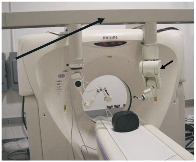
Computed tomography gantry in the interventional radiology suite of the future has a frame (long arrow) that localizes tools in relation to CT space. Robot (short arrow), electromagnetic field generator, and passive arm with diagnostic and therapeutic focused US are shown. The US transducer may also be registered to the CT with software and tracked with electromagnetic or optical-based sensors attached to the transducer. These sensors give position and orientation information in relation to imaging before RFA.
Finite Element Analysis Computational Model
Defining tissue at risk for under-treatment or underheating (given known sequential needle positioning) may be estimated with computational models based on finite element analysis (FEA) and the Pennes bioheat equation. The bioheat equation is a way to estimate heat effects upon tissue with a basic engineering knowledge of tissue properties and electromagnetic energy. It can be simplified as energy in minus energy out (heat sink, convective heat loss) equals energy deposition and treatment effect. Finite element analysis is a computationally intensive method for mathematical modeling.
Once defined during a treatment, the specific area most at risk for having gaps or clefts or underheated viable tumor may be appropriately targeted (Fig 8) (6–8). Current standard techniques offer little guidance in treatment other than the physician’s intuition, which is often based on a mental image of the tumor imagined by the physician many minutes or hours prior to the procedure.
Figure 8.

Thermal models superimposed onto axial (a), sagittal (b), and coronal (c) CT views during RFA of a liver lesion. During an ablation, thermal models may be placed at the actual needle location coordinates and fused with CT MPR to retrospectively visualize the expected treatment effect or degree of success for a specific ablation location. This may help determine the need for additional ablations and the location of those ablations, based on tissue at risk for undertreatment.
Patient-specific FEA models can be generated to estimate isotherms for a given needle location. Isotherms are estimations of temperature along a curvilinear line (like a contour map). Superimposing isotherms on planning CT images helps predict RFA effects and potential injury to non–target tissue, as coagulation necrosis occurs above ~50°C (Fig 9). Thermal models are computed with and without vessel occlusion by adjusting the perfusion term in the bioheat equation to determine the need for adjunctive maneuvers like vessel occlusion or embolization to minimize heat sink (Fig 4). Selections of skin entry and target points generate a 3D treatment plan with MPR views for robotic-assisted RFA (Fig 10). The 3D centerline coordinates of the virtual electrodes are sent to a CT-integrated robot for automatic alignment with the planned trajectories to assist placement.
Figure 9.

(a) Sagittal reconstruction image of unenhanced CT shows treatment planning model of proposed ablation zone with colorized isotherms depicting result of ablation of liver dome lesion. The treatment planning model predicts that the heart would reside within the predicted 50°C isotherm (blue ring, arrow), potentially causing damage to heart or pericardium. (b) Sagittal reconstruction image of enhanced CT after perihepatic infusion of 1,000 mL of 5% dextrose water. If RFA were performed at this time point without further dextrose instillation, the model predicts the remaining potential to damage the pericardium. (c) Sagittal reconstruction images of enhanced CT after perihepatic infusion of an additional 1,000 mL (total 2,000 mL) of 5% dextrose water. The heart now does not reside within the predicted heated isotherm because of displacement and insulation from protective water blanket (arrow), as well as rotation of the liver due to large-volume infusion. Enhanced CT image obtained immediately after RFA showed no evidence of damage to heart or pericardium, with local control of the lesion by CT and MR imaging 3 months after RFA (after a second RFA to complete treatment of tumor border opposite heart and left hepatic vein).
Figure 10.

“Point-and-click” robotic-assisted ablation is possible after rapid selection of (a) skin entry and (b) target points with planning display of simulated ablation volume (c, d).
A finite element computer model was created that included vessel geometry (coordinates imported from segmented CT) and RF electrode position. The model simulated 12-minute impedance controlled, cool-tip cluster RF ablation (ValleyLab, Boulder, Colo), similar to previous studies (6,7,9). Vessel cooling was simulated by assigning a convective heat transfer coefficient as boundary condition (5,6). Models were created with and without perfusion effects (Fig 4). The thermal model was then displayed with colorized isotherms fused with the source CT images. Thermal models located at virtual needle coordinates were fused retrospectively with preablation source CT to simulate the effects of a specific needle location. Treatment simulation may predict damage to adjacent heat-sensitive structures (such as bowel or heart) (Fig 9). This may predict the necessity of adjunctive maneuvers (like fluid instillation or balloon occlusion). Thermal models located at actual imaged needle coordinates were also fused with intraprocedural CT MPR to visualize retrospectively the degree of success of a specific ablation location (Figs 6, 8). With faster computational means, such models could eventually be computed during the procedure and combined with thermometry to provide intraprocedural feedback.
THERAPY-SPECIFIC TREATMENT PLANNING
One example of the importance of treatment planning as a developmental tool is demonstrated by drug-device combination therapies, such as heat-activated drug delivery with ablation energies. For example, heat-activated liposomal doxorubicin (Thermo-Dox TM; Celsion Corp., Columbia, Md) deploys chemotherapy around an ablation zone, and the cargo is deployed at 39°C to 42°C (11). Computational modeling with multiple isotherms could optimize algorithms, as well as provide a patient-specific region of expected effect, or expected drug deposition. In this case, visualizing the anatomic location of the 39°C isotherm might be key to effective local ablation. For temperature-controlled RFA (RITA Medical, Mountain View, Calif), direct visualization of the temperatures at the edge of the ablation zone, where tissues are at highest risk for recurrence, might provide important visual feedback regarding the location of tissue at risk for undertreatment.
Temperature Feedback on Computed Tomography
Spatial display of thermometry feedback during a procedure may facilitate repositioning or rotation of a coaxially deployed ablation device. Knowing the temperature at the tips of specific tines and the location of those tines could have significant value during an ablation. Computed tomographic thermometry could provide feedback during ablations, and there is a known linear relationship between CT numbers and temperature that has not yet been commercialized (10). However, CT thermometry software may enable near real-time display of voxel temperatures during CT-guided ablation (Fig 11).
Figure 11.

Computed tomographic thermometry after 11 minutes of heating a hepato-cellular carcinoma tumor in the liver. Computed tomographic thermometry software is being developed that displays the temperature of the tissue in CT during RFA of a hepatoma. (Courtesy of Abla-Tx, Boulder, CO, and Charlie Nutting, DO.)
Convective heat loss (heat sink) was simulated during RFA with a RITA XLi needle system (RITA Medical) in an ex vivo cow liver with CT-integrated robotic guidance (Fig 12). A set of virtual electrodes formed an ablation plan based on overlapping spheres defined by estimated isothermal contours, whose shape and size can be adjusted. Temperature feedback was superimposed on CT images during RFA, which demonstrated a heat sink. Repeat RFA in a new position was performed based on the combination of temperature and visual CT feedback. By placing the outer cannula near but not in the simulated vessel, the temperatures could be raised higher at the edge of the simulated vessel, where the heat sink effect would otherwise lead to residual tumor.
Figure 12.

Convective heat loss (heat sink) was simulated during RFA with a RITA XLi needle system (RITA Medical, Mountain View, CA) in an ex vivo cow liver with CT-integrated robotic guidance. (a) Test bed shows needle insertion toward simulated vessel (arrow). Target selection was made on CT software, and robot automatically pointed a laser to select needle insertion point and angle. (b) Detailed schematic of test bed. (c) Computed tomography confirms tine adjacent to simulated vessel (arrow). (d) Time-temperature graph shows one tine with lower temperature (arrow) due to heat sink.
The anatomic localization of specific temperature feedback may provide vital information during probe repositioning to optimize the dynamics of the RFA treatment zone and to minimize the effects of heat sink from vessels. This anatomic/temperature feedback facilitates repositioning to optimize maximum temperature near blood vessels, which might have otherwise resulted in residual viable tumor cells adjacent to the vessel wall. Combining temperature feedback with exact anatomic location may be a powerful tool in improving outcomes of RFA.
SEMIAUTOMATIC ROBOTIC GUIDANCE AND NEEDLE INSERTION
Computed tomography–integrated robotic needle placement provides a semiautomatic way to implement a predetermined treatment plan, which allows the physician to remain in control of the needle placement (8,13). The robot is attached to the CT gantry and thus is preprogrammed with the CT 3D coordinate system (Fig 7). “Point-and-click” ablation is possible after rapid selection of virtual skin entry and target points, with the planning display of resulting ablation volume (Fig 8). The CT-integrated robot (NIH, Bethesda, Md, and Philips Medical Systems, Cleveland, Ohio) is different than other previously reported CT-compatible robots in that it is a single platform with true seamless integration and does not require the time-consuming steps of frame grabbing, accessory computers, intraprocedure registration steps, or extra software (12). The CT-integrated robot is able to insert the needle with a pneumatic gripper using remote controls (automatic insertion); however, the physician may choose to remain in control of the procedure using the telescoping clamp or laser guidance end effector options (semiautomatic insertion) (10,13). The laser points out the correct angulation and insertion point for the prescribed needle insertion and illuminates the needle hub during manual placement.
ELECTROMAGNETIC TRACKING AND NAVIGATION
Optical and electromagnetic (EM) tracking are standard techniques for registration of preoperative images during neurosurgery and orthopedic surgery but have not been widely applied in interventional radiology. Tracking allows for use of preprocedural images during the procedure and displays the needle or guide-wire location in relation to the preprocedural images (Fig 13a–d). In addition, tracking allows fusion and use of multiple modalities such as real-time US plus pre-operative CT. Medical devices like needles, catheters, guide wires, or US are tracked with small coils (Traxtal Technologies, Toronto, Ontario, Canada) that provide location information in real time in relation to preoperative imaging (CT, MR, PET). This tracking requires either infrared or optical cameras (Fig 14) or a small EM field generator and software (Fig 13a). The miniaturization of EM sensor coils allows localization and tracking of internal medical devices, whereas optical tracking requires direct line of sight, which is less useful for image-guided therapy in interventional radiology. Miniaturized position sensors are placed inside the tips of ablation needles and guiding needles to give real-time feedback of needle position during the ablation, similar to a miniaturized global positioning system (14). The knowledge of ablation needle location within a preprocedural data set provides a “multimodality road map” during needle manipulations. This information may facilitate needle placement or repositioning, especially when real-time visualization is suboptimal, as when gaseous clouds obscure US visualization. Tumors that are only seen during arterial-phase CT or PET are also potentially better targeted with such navigation tools. Tracking of the US transducer or the moving liver may be combined with tracking of the ablation needle itself. Navigation fits well into the treatment-planning paradigm. External devices such as US transducers can be tracked with optical techniques (Fig 14), whereas electromagnetic tracking allows internal device tracking that does not require direct line of sight.
Figure 13.

(a) Multimodality procedure room during liver RFA using electromagnetic tracking to guide needle placement. The electromagnetic field generator is placed in close proximity to the needle insertion site (arrow). (b) Skin fiducials, visible on CT, are placed around the procedure site and used to register and map the electromagnetic field space to the CT coordinates. (c) Virtual needle location displayed in real time on immediate pretreatment CT scan after registration with skin fiducials (white arrow). (d) Actual RFA needle (thick arrow) placed with electromagnetic tracking of needle tip (thin arrow) to treat residual tumor along margin of previous thermal lesion.
Figure 14.

The US transducer (black arrow) may be registered to the CT with software and tracked with electromagnetic or optical-based sensors (white arrows) attached to the transducer. These sensors give position and orientation information in relation to imaging performed before RFA. Supported in part by the SIR Foundation Pilot Research Grant Program.
MULTIMODALITY IMAGING
The combination of several imaging modalities, such as US and CT, into a single multimodality image can improve image guidance in several ways by taking advantage of the anatomic details from CT with the real-time feedback from US without radiation. Neither modality alone is ideally suited to provide image guidance during RFA. The target lesion itself may not visualize well under CT, as may happen with hepatocellular carcinoma, visible only in the arterial phase due to robust parasitization of hepatic arterial blood supply. Ultrasound imaging is also affected by the generation of gas bubbles in the tissue due to heating once the ablation is started. The cloud of gas bubbles does not allow the US waves to penetrate to deeper tissues, which are thus obscured by dark shadows in the image. This phenomenon, also referred to as gassing out of the underlying tissues, prohibits effective US guidance if several locations in close proximity need to be treated.
The registration and fusion of real-time US imaging with a preacquired 3D image such as CT (Figs 15, 16 ) addresses some of these difficulties (3,12). Path planning is possible in the 3D image, and the execution of the plan is verified in real time using the US image. Combining the two modalities also increases the likelihood of target lesion visualization, and the relative contribution of the two modalities to the combined image can be adjusted to maximize lesion contrast (Fig 16). Displaying the real-time image of the needle within the larger, higher resolution CT image may also assist in using other internal landmarks for navigation (even if the target lesion cannot be visualized in either modality). Furthermore, the gassing out of the US image is addressed by displaying the corresponding region of the CT image in those areas affected by the gas bubbles.
Figure 15.
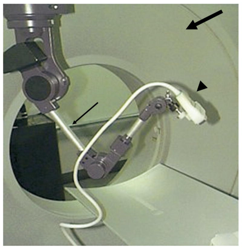
The registration and fusion of real-time ultrasound with a preacquired 3D image (such as CT) can provide more spatial information on target tumor and its relationship to treatment zone than conventional methods. Ultrasound (arrowhead) may be registered to CT by means of optical or electromagnetic tracking or by a passive arm (thin arrow) attached to the CT gantry (thick arrow). Supported in part by the SIR Foundation Pilot Research Grant Program.
Figure 16.

Fusion of US and CT images of an abdominal phantom is updated in real time, based on electromagnetic tracking of the ultrasound probe. (a) The ultrasound image is emphasized. (b) More blending of corresponding CT is displayed.
Real-time US and CT image fusion is enabled by electromagnetic tracking of the US probe (Fig 16). The two-dimensional (2D) US image is superimposed with variable opacity with blending onto the corresponding slice in the CT volume. The alignment is maintained as the US transducer is moved with real-time updating of fused US and CT images to visualize lesions in both modalities, with graded relative weighting or blending of modalities (Fig 16).
SOFTWARE
Many different software options are described above. The joining of CT with patient-specific thermal modeling was performed jointly with modifications of existing CT software prototypes (Philips Medical Systems). Thermal modeling computations were performed with commercial software (Abaqus Inc., Paw- tucket, RI), where custom subroutines were implemented for impedance-controlled ablation and simulation of blood flow; geometry of segmented vasculature was imported from CT images to obtain a patient-specific model. Registration and fusion options include Mx-View and Pinnacle (Philips Medical Systems), as well as an NIH-written, Java-based image processing software (MIPAV) modified to semiautomatically segment, threshold, and display preprocedural images, as well as fuse images obtained before and after RFA. Treatment planning with overlapping sphere-packing was planned on CT software (Philips Medical Systems), as well as virtual needle plans and robotic needle placement done or assisted by the CT-integrated robot (Philips Medical Systems). Several software solutions offer volumetric display of simulated RFA needles (NIH MIPAV; Philips Medical Systems) for treatment planning. Co-registered ultrasound and CT were blended with custom software (Philips Medical Systems; Philips Research USA; Philips Research Hamburg). Electromagnetic tracking for virtual display of ablation needles within preoperative images was performed with two sets of software (Philips Research; ISIS George-town University Medical Center).
CONCLUSIONS
Image-guided therapy has not yet fully used the first two words in its name: image-guided. The real-time feedback provided by imaging and facilitated by treatment planning could improve outcomes, facilitate ablation, and convert ablation to a more routine, iterative procedure similar to radiation therapy. Semiautomated simulation and treatment planning may better plan RFA with semiautomatic segmentation of vessels, organs, and tumor, followed by virtual needle placement. The treatment plan may include patient-specific isotherms that help predict the need for adjunctive maneuvers, such as balloon occlusion or fluid instillation. Fusion of images obtained before and after RFA may enable real-time adjustment of the RFA to treat tissue most at risk of undertreatment, given the known, actual RFA needle locations. Robotic RFA needle insertion, which is guided by a truly integrated CT robot, allows for seamless, iterative, “point-and-click,” “see-and-treat,” patient-specific RFA, thereby making use of image processing and available technologies for automation, navigation, and visualization. Hopefully, such technology tools will translate into improved patient outcomes.
Acknowledgments
This work was supported in part by the Intramural Research Program of the NIH Clinical Center and was presented at the Radiological Society of North America Annual Meeting 2004. This work was also supported in part by the National Institutes of Health, Grant C06 RR018823 from the Extramural Research Facilities Program of the National Center for Research Resources and the Society of Interventional Radiology Foundation Pilot Research Grant Program.
Abbreviations
- EM
electromagnetic
- FEA
finite element analysis
- MPRs
multiplanar reconstructions
- PET
positron emission tomography
- RF
radio-frequency
- RFA
radiofrequency ablation
Footnotes
J.Y. is a salaried employee of Philips Medical Systems, Cleveland, OH. J.K. is a salaried employee of Philips Research North America, Briarcliff Manor, NY. N.G. is president and a major shareholder of Traxtal Technologies, Inc., Toronto, Ontario, Canada. B.W., J.K., K.C., N.G., Philips Medical, Traxtal Technologies, and NIH have intellectual property in related fields. None of the other authors have identified a conflict of interest.
References
- 1.Hori T, Nagata K, Hasuike S, et al. Risk factors for the local recurrence of hepatocellular carcinoma after a single session of percutaneous radiofrequency ablation. J Gastroenterol. 2003;38:977–981. doi: 10.1007/s00535-003-1181-0. [DOI] [PubMed] [Google Scholar]
- 2.Yu HC, Cheng JS, Lai KH, et al. Factors for early tumor recurrence of single small hepatocellular carcinoma after percutaneous radiofrequency ablation therapy. World J Gastroenterol. 2005;11:1439–1444. doi: 10.3748/wjg.v11.i10.1439. [DOI] [PMC free article] [PubMed] [Google Scholar]
- 3.Wood BJ, Banovac F, Friedman M, et al. CT-integrated programmable robot for image-guided procedures: comparison of free-hand and robot-assisted techniques. J Vasc Interv Radiol. 2003;14:S62. [Google Scholar]
- 4.Roche A, Malandain G, Pennec X, Ayache N. The correlation ratio as a new similarity measure for mulitimodal image registration. In: Wells WM, Colchester A, Delp S, editors. Proceedings of the First International Conference on Medical Image Computing and Computer-Assisted Interventional Radiology; October 11–13, 1998; Cambridge, MA Springer Verlag, Berlin, Germany. 1998. p. 1124. [Google Scholar]
- 5.Cebral J, Soto O, Lutz R, Wood BJ. Effects of blood flow on radiofrequency ablation of tumors: finite elements and in vitro models. In: Sacks M, Hefzy MS, Bischof J, editors. Advances in Bioengineering; Proceedings of the ASME International Mechanical Engineering Congress and Exposition; November 16–21, 2003; Washington, DC. New York, NY: American Society of Mechanical Engineers; 2003. pp. 5–6. [Google Scholar]
- 6.Haemmerich D, Wright AW, Mahvi DM, Lee FT, Jr, Webster JG. Hepatic bipolar radiofrequency ablation creates coagulation zones close to blood vessels: a finite element study. Med Biol Eng Comput. 2003;41:317–323. doi: 10.1007/BF02348437. [DOI] [PubMed] [Google Scholar]
- 7.Haemmerich D, Chachati L, Wright AS, Mahvi DM, Lee FT, Jr, Webster JG. Hepatic radiofrequency ablation with internally cooled probes: effect of coolant temperature on lesion size. IEEE Trans Biomed Eng. 2003;50:493–500. doi: 10.1109/TBME.2003.809488. [DOI] [PubMed] [Google Scholar]
- 8.Wood BJ, Viswanathan A, McCreedy E, et al. Semi-automated treatment planning software for RFA. J Vasc Interv Radiol. 2005;16:S72. [Google Scholar]
- 9.Tungjitkusolmun S, Staelin ST, Haemmerich D, et al. Three-dimensional finite-element analyses for radio-frequency hepatic tumor ablation. IEEE Trans Biomed Eng. 2002;49:3–9. doi: 10.1109/10.972834. [DOI] [PubMed] [Google Scholar]
- 10.Fallone BG, Moran PR, Podgorsak EB. Noninvasive thermometry with a clinical x-ray CT scanner. Med Phys. 1982;9:715–721. doi: 10.1118/1.595117. [DOI] [PubMed] [Google Scholar]
- 11.Pritchard WF, Friedman MA, Karanian JW, et al. Heat-sensitive liposomes as carriers for doxorubicin increase local drug deposition during radiofrequency ablation. Proceedings of the RSNA 89th Annual Scientific Assembly and Annual Meeting; November 30–December 4, 2003; Chicago, IL. Online at: http://rsna2003.rsna.org/rsna2003/VBK/conference/event_display.cfm?em_id=3800056. [Google Scholar]
- 12.Solomon SB, Patriciu A, Bohlman ME, Kavoussi LR, Stoianovici D. Robotically driven interventions: a method of using CT fluoroscopy without radiation exposure to the physician. Radiology. 2002;225:277–282. doi: 10.1148/radiol.2251011133. [DOI] [PMC free article] [PubMed] [Google Scholar]
- 13.Wood BJ, Renisch S, Viswanathan S, et al. In: Lemke HU, Inamura K, Doi K, et al., editors. CT-integrated treatment planning for robot-assited thermal ablation and laser-guided sphere packing. Computer Assisted Radiology and Surgery; Proceedings of the Computer Assisted Radiology and Surgery 19th International Congress and Exhibition; June 22–25, 2005; Berlin, Germany. Amsterdam, The Netherlands: Elsevier B.V.; 2005. p. 1361. [Google Scholar]
- 14.Wood BJ, Zhang H, Durrani A, et al. Navigation with electromagnetic tracking for interventional radiology procedures: a feasibility study. J Vasc Interv Radiol. 2005;16:493–505. doi: 10.1097/01.RVI.0000148827.62296.B4. [DOI] [PMC free article] [PubMed] [Google Scholar]