Abstract
PURPOSE
To evaluate the spatial accuracy of electromagnetic needle tracking and demonstrate the feasibility of ultrasonography (US)–computed tomography (CT) fusion during CT- and US-guided biopsy and radiofrequency ablation procedures.
MATERIALS AND METHODS
The authors performed a 20-patient clinical trial to investigate electromagnetic needle tracking during interventional procedures. The study was approved by the institutional investigational review board, and written informed consent was obtained from all patients. Needles were positioned by using CT and US guidance. A commercial electromagnetic tracking device was used in combination with prototype internally tracked needles and custom software to record needle positions relative to previously obtained CT scans. Position tracking data were acquired to evaluate the tracking error, defined as the difference between tracked needle position and reference standard needle position on verification CT scans. Registration between tracking space and image space was obtained by using reference markers attached to the skin (“fiducials”), and different registration methods were compared. The US transducer was tracked to demonstrate the potential use of real-time US-CT fusion for imaging guidance.
RESULTS
One patient was excluded from analysis because he was unable to follow breathing instructions during the acquisition of CT scans. Nineteen of the 20 patients were evaluable, demonstrating a basic tracking error of 5.8 mm ± 2.6, which improved to 3.5 mm ± 1.9 with use of nonrigid registrations that used previous internal needle positions as additional fiducials. Fusion of tracked US with CT was successful. Patient motion and distortion of the tracking system by the CT table and gantry were identified as sources of error.
CONCLUSIONS
The demonstrated spatial tracking accuracy is sufficient to display clinically relevant preprocedural imaging information during needle-based procedures. Virtual needles displayed within preprocedural images may be helpful for clandestine targets such as arterial phase enhancing liver lesions or during thermal ablations when obscuring gas is released. Electromagnetic tracking may help improve imaging guidance for interventional procedures and warrants further investigation, especially for procedures in which the outcomes are dependent on accuracy.
Minimally invasive imaging-guided procedures such as radiofrequency ablation (RFA) have received increasing attention in recent years (1–15). Imaging guidance is crucial for accurate needle probe placement, and outcomes likely depend on accurate probe placement and repositioning, which may be complicated by complex geometries and inadequate real-time positional feedback. Currently, imagng guidance for such procedures is suboptimal, may use relatively high doses of radiation for computed tomography (CT) and CT-fluoroscopic guidance, and/or makes inefficient use of existing imaging modalities. For needle insertions, ultrasonography (US) and CT are the primary guidance modalities (16,17). However, US visualization of liver masses can be poor, and even preprocedural and contrast medium–enhanced CT may not provide adequate visualization (18,19). In these cases, the conventional procedure involves the estimation of target position by using nearby discernable anatomy and “mental co-registration” with a previously obtained three-dimensional image. In addition, the US visualization of the needle is strongly dependent on the needle angle and is limited by partial-volume averaging (20). The obstruction of the US image by gas microbubbles released during thermal treatment is an additional challenge. Such factors can lead to inaccurate needle placement, repeat needle placement, or extended procedure times with conventional methods. Although CT enables three-dimensional path planning and accurate verification of needle position, the time requirements and patient radiation dose may be substantial, especially for pathways with complex angles or narrow windows.
Miniaturization of electromagnetic sensors and needles with sensors integrated inside the tip has enabled spatial tracking of needles and facilitates needle insertions out of the US or CT imaging plane (21–23). Multimodality guidance enabled by electromagnetic tracking of devices can augment single-modality imaging guidance (21–24). Internalization of the sensors has allowed this technique to mature and differentiates it from prior reported experience. Internalized needle tip sensors actually track and follow the motion of the needle itself and do not rely on the estimation of needle position on the basis of external needle hub position. This can correct for needle bending, organ motion, and respiration.
This study is a translational clinical trial of internally tracked needles for biopsy and interventional RFA. The purpose of our study was to evaluate spatial accuracy of electromagnetic needle tracking and demonstrate the feasibility of US-CT fusion during CT-and US-guided biopsy and RFA procedures.
MATERIALS AND METHODS
Patient Population and Setup
The clinical trial was approved by the institutional investigational review board, and all patients gave written informed consent. The patient population was composed of 14 men and six women with a mean age (±standard deviation) of 52.4 years ± 14.7. Eight patients underwent RFA; the remainder underwent needle biopsy. Ten patients were treated in the supine position, three in the prone position, and seven in the decubitus position. Details of the procedures are given in Table 1.
Table 1.
Summary of Procedure Details and Basic Tracking Error
| Patient No. | Location | No. of Sites | Maximum Diameter (cm) | Type of Procedure | Patient Position | No. of Tracked Needle Positions | No. of Fiducials | Fiducial Registration Error (mm) | Basic Tracking Error (mm) |
|---|---|---|---|---|---|---|---|---|---|
| 1 | Right lobe of liver | 9 | 3 | RFA | Supine | 8 | 6 | 2.2 | 4.8 ± 0.9 |
| 2 | Liver dome | 2 | 2.2 | RFA | Supine | 4 | 6 | 2.7 | 5.7 ± 1.2 |
| 3 | Periportal liver | 1 | 1.8 | Biopsy | Supine | 4 | 7 | 1.9 | 5.8 ± 0.5 |
| 4 | Liver dome | 1 | 1.3 | Biopsy | Supine | 4 | 7 | 3.0 | 3.8 ± 1.5 |
| 5 | Right kidney | 1 | 2.5 | Biopsy | Decubitus | 2 | 5 | 1.0 | 6.9 ± 0.5 |
| 6 | Liver dome | 2 | 2.5 | Biopsy | Supine | 4 | 6 | 1.9 | 15.8 ± 5.9 |
| 7 | Liver | 3 | 4 | RFA | Decubitus | 4 | 6 | 1.4 | 3.2 ± 0.7 |
| 8 | Left upper lobe of Lung | 1 | 3.7 | Biopsy | Supine | 3 | 6 | 2.0 | 11.9 ± 1.4 |
| 9 | Liver | 8 | 4 | RFA | Supine | 3 | 7 | 1.0 | 4.7 ± 0.9 |
| 10 | Left plural base | 2 | 3 | Biopsy | Decubitus | 2 | 6 | 1.6 | 6.6 ± 0.7 |
| 11 | Posterior left chest | 1 | 4.5 | Biopsy | Prone | 2 | 6 | 2.0 | 5.6 ± 0.5 |
| 12 | Right kidney | 1 | 4.7 | RFA | Supine | 5 | 6 | 2.1 | 10.1 ± 1.6 |
| 13 | Liver dome | 4 | 2.3 | Biopsy | Supine | 4 | 6 | 1.9 | 5.1 ± 2.8 |
| 14 | Liver, left/right lobe Junction | 2 | 0.8 | Biopsy | Supine | 1 | 7 | 2.8 | 4.4 |
| 15 | Left kidney | 1 | 4.8 | RFA | Decubitus | 3 | 7 | 1.7 | 5.3 ± 1.3 |
| 16 | Between upper left kidney and spleen | 3 | 3.5 | RFA | Decubitus | 2 | 7 | 1.6 | 2.9 ± 0.2 |
| 17 | Paravertebral mass | 1 | 3.5 | RFA | Decubitus | 3 | 6 | 1.2 | 3.5 ± 0.8 |
| 18 | Left posterior lung | 1 | 1 | Biopsy | Prone | 3 | 5 | 1.4 | 8.9 ± 1.0 |
| 19 | Left kidney | 1 | 1.8 | Biopsy | Decubitus | 1 | 7 | 2.4 | 3.5* |
| 20 | Right retroperitoneal Mass | 1 | 6.2 | Biopsy | Prone | 3 | 7 | 2.1 | 4.7 ± 2.0 |
Note. The mean maximum diameter was 3.1 cm ± 1.4; the mean number of tracked needle positions was 3.3 ± 1.6; the mean number of fiducials was 6.3 ± 0.7; the mean fiducial registration error was 1.9 mm ± 0.6; and the mean basic tracking error was 6.4 mm ± 3.7.
After motion compensation.
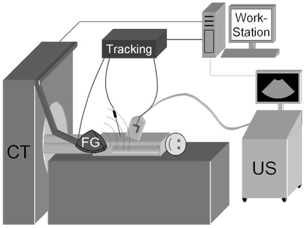
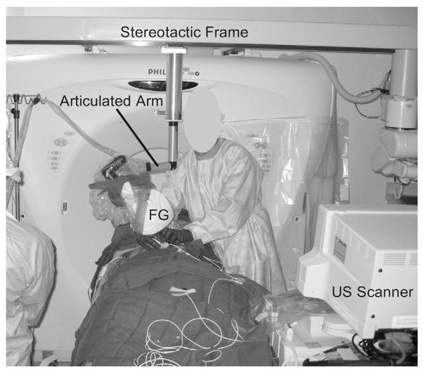
The setup is illustrated in Figure 1. All procedures were performed with a 16-slice CT scanner (MX 8000; Philips Medical Systems, Cleveland, Ohio). In addition, HDI 5000 or IU-22 scanners (Philips Medical Systems) were used for US guidance of the liver and kidney procedures. A tracking system (Aurora; Northern Digital Inc., Water-loo, Ontario, Canada) with tetrahedral generator was used for electromagnetic tracking. The generator was mounted on an articulated mechanical arm, which was attached to a stereotactic frame connected to the CT gantry (Fig 2).
Figure 1.
Diagram of research work station, tracking equipment with field generator (FG), and US scanner in the CT suite for tracked needle-based interventional procedures.
Figure 2.
Photograph of an interventional procedure in the CT suite. The electromagnetic field generator (FG) is mounted on an articulated arm, which is connected to the CT gantry. Both the generator and arm are covered with a sterile cover.
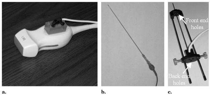
The US transducer was tracked by using a 6-df electromagnetic position tracking sensor (Traxtal, Toronto, Canada), which was attached to the handle of the transducer (Fig 3a). Needles were tracked as well. Two types of custom-built needles (Traxtal) with 5-df electromagnetic sensors integrated inside the needle tip were used. Stylet-sheath combinations (18–22 gauge) were used for biopsies (Fig 3b), and three-hole radiofrequency needle guides (19 gauge) were used for RFA (Fig 3c). The three-hole guide is compatible with the three-prong RFA cluster needle (Cool-Tip; Valleylab, Boulder, Colo), which was used in all but one of the ablation cases. One procedure was performed with a single RFA needle with co-axial technique by using a tracked stylet-sheath combination.
Figure 3.
(a) S4-1 US transducer with a 6-df electromagnetic position sensor attached. (b) Tracked stylet-sheath combination. (c) Tracked three-hole needle guide.
Procedure
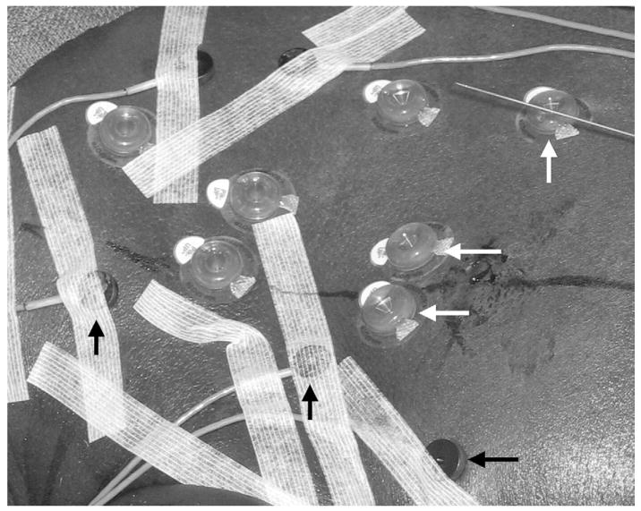
The patients were positioned on a vacuum stabilization mattress on the CT table. Conscious sedation was used for patients who underwent biopsy, and general endotracheal anesthesia was used for those who underwent RFA. An initial US examination was performed to estimate the skin entry site and US imaging window. Five to seven sterile passive fiducial markers (Beekley, Bristol, Conn) and five to eight sterile, actively tracked custom fiducials with 5-df sensors integrated directly inside the fiducial (Traxtal) were placed on the skin near the planned needle entry point (Fig 4). A sterile skin grid was placed loosely over the skin surface in the general area of needle insertion.
Figure 4.
Photograph of passive (white arrows) and actively tracked (black arrows) fiducials attached to the skin. The passive fiducials are 15 mm in diameter and have a central divot in which to place the needle during registration. The active fiducials are 11 mm in diameter and contain a 5-df sensor coil.
A preprocedural CT scan (3-mm-thick sections, 1.5-mm overlap) was obtained at expiration breath-hold in sedated patients or during interruption of ventilation in the end expiration phase in patients under general anesthesia. Intravenous administration of contrast medium was used to visualize the target in nine patients. The CT phase with the greatest target conspicuity was sent by Digital Imaging and Communications in Medicine transfer to the research navigation workstation in the procedure room.
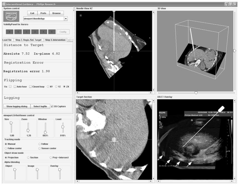
With use of custom software on that workstation (Fig 5), skin fiducials were identified manually on the CT scan. The corresponding tracking coordinates were obtained by pointing the tracked needle to each of the fiducials during the breath hold and averaging the tracking signal for several seconds until a stable reading was obtained. The registration times were recorded for all patients.
Figure 5.
Screenshot of the custom navigation software shows multiplanar reconstructions (MPRs) of the preprocedural CT scan relative to the tracked needle position (top row), needle angle and position relative to the target site (bottom left), and the US-CT fusion display with variable transparency of the US scan (bottom right). In this image, the fusion display shows the US scan with high opacity, revealing only some of the rib structures of the underlying CT scan (white arrows). Figure 9 shows an enlargement of this fusion display, with a corresponding CT-only view for easier comparison with the US scan.
A rigid (ie, rotation + translation) registration transformation between tracking coordinates and CT image coordinates was computed, and the root-mean-square distance (fiducial registration error) between the CT image coordinates of the fiducials and the transformed tracking coordinates of the fiducials was calculated and displayed. The registration procedure was repeated up to three times or until the fiducial registration error was smaller than 2 mm. The registration with the lowest fiducial registration error was used henceforth.
This manual “standard” registration procedure was compared to automatic registrations obtained additionally in three patients by using the five to eight actively tracked custom fiducials with integrated sensors (Fig 4). Tracking coordinates from all active fiducials were obtained automatically during expiration breath hold or interruption of ventilation. Tracking errors were compared for active and conventional fiducials.
The needle insertion was performed at expiration breath hold or interruption of ventilation under US guidance, except for the lung and paravertebral sites, followed by CT verification scanning. Verification scanning was repeated when clinically indicated and during needle repositioning, for a total of one to six scans per patient. Needle tracking data were recorded, but the operator was blinded to the tracking display. For biopsies, the tracked stylet was then withdrawn from the stylet-sheath combination and replaced by the biopsy needle. For RFA, the RFA probe was inserted through the back and front holes of the tracked needle guide, with the three needle prongs surrounding the tracked guider needle.
No tracking information was acquired during CT because the generator was mounted outside the CT gantry (Fig 2). Instead, tracking data were used at expiration breath hold immediately before or after verification scanning. If no breath hold could be obtained (in 30 of the 65 total data points), tracking data from the expiration phase of respiration were used instead.
Setup time for all additional steps necessary to run the tracking system was recorded in one patient (patient 19) after the team gained experience with the system.
Tracking Error Calculation
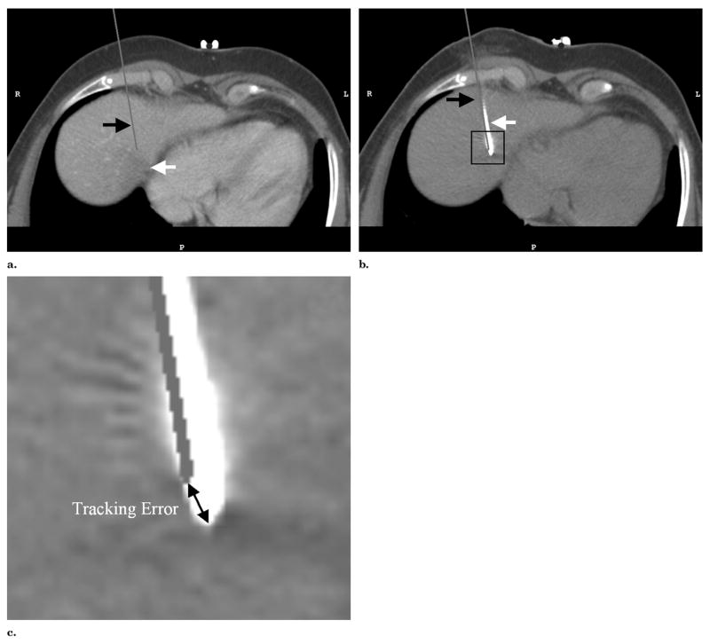
The basic tracking error was defined as the distance between the “virtual” needle position computed with the tracking data and the standard of reference needle position extracted from the verification scans (Fig 6).
Figure 6.
(a) MPR of a preprocedural CT scan shows the target lesion (white arrow) with the virtual needle (black arrow) superimposed on the basis of the needle’s tracking position and registration immediately before a confirmation CT scan was obtained. (b) The same MPR in the confirmation scan shows the image of the 19-gauge tracked needle (white arrow) and the superimposed virtual needle (black arrow). The thick end of the needle in the CT scan of the needle indicates the location of the integrated 9 × 1-mm sensor coil. (c) Magnified image of the needle tip corresponding to the inset in b. The corresponding tracking error is indicated as the distance between the three-dimensional positions of the virtual needle tip and needle image.
The patient population was divided into subgroups according to target site, patient position, and use of ventilation, and the basic tracking error was computed for each subgroup. To determine potential sources of error, the basic tracking error was also correlated with the distance between the needle tip and CT table and the distance between the needle tip and electromagnetic field generator.
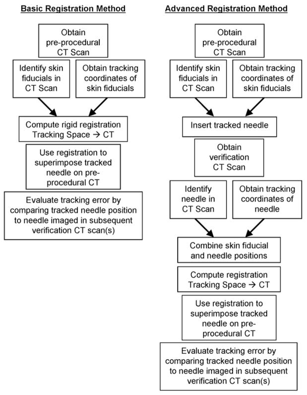
Two different registration methods were compared (Fig 7). First, rigid registrations based only on external fiducials were computed. Second, rigid and affine (ie, linear but nonrigid, including shearing and scaling) registrations were calculated by including CT-confirmed previous needle positions as additional fiducial markers for the remainder of the study. These registrations were evaluated by using needle positions confirmed with subsequent verification scans.
Figure 7.
Flow chart of the basic and advanced registration methods.
US-CT fusion
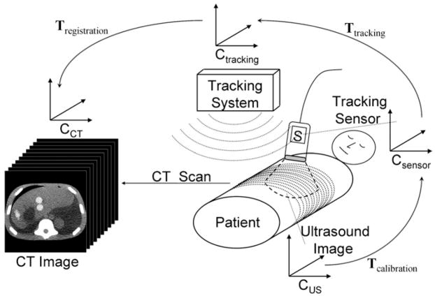
Spatial tracking of the US probe and registering the tracking coordinate system with the CT coordinate system enables real-time fusion of the live US image with the spatially corresponding MPR from the CT scan. The calculation of the CT MPR requires a chain of transformations between different coordinate systems, as illustrated in Figure 8. A calibration procedure was carried out once before the trial to determine the transformation Tcalibration from the US scan coordinate system to the coordinate system of the electromagnetic tracker attached to the US probe. The calibration procedure followed a commonly used technique involving imaging of a point target (25,26). Singular value decomposition was used to determine the least-squares match between US image coordinates and tracking coordinates. The transformation Ttracking between the electromagnetic tracker on the US probe and the tracking coordinate system is given by the real-time readout of the tracker’s position and orientation. The transformation Tregistration between the tracking coordinate system and the CT scan was provided by the registration procedure described earlier. Thus, the joint transformation T2DUS→3DCT = Tregistration · Ttracking · Tcalibration converts from two-dimensional US (2DUS) coordinates to three-dimensional CT (3DCT) coordinates and enables the calculation of the CT MPR corresponding to the live US image.
Figure 8.
Diagram of the transformation chain used to fuse the real-time US scan with the corresponding CT MPR. The two-dimensional US scan, the tracking sensor attached to the US probe, the tracking system, and the volumetric CT scan each have their own coordinate system CUS, Csensor, Ctracking, and CCT, respectively. Rigid body transformations T transform the coordinates from one coordinate system to another.
Statistical Analysis
Statistical analysis was performed by using MATLAB software (version 7 R14, The MathWorks, Natick, MA). Unpaired t tests were used to determine statistically significant differences (P < 05) in tracking error between subgroups of the population. Paired t tests were used to determine differences (P <.05) between different registration techniques. Linear regression analysis was used to determine the dependency of the tracking error on the distances from the CT table and from the field generator.
RESULTS
The registration procedure, that is, the acquisition of tracking data from the skin fiducials and calculation of the registration transformation, took an average of 131 seconds per patient. The total system setup time was 5.25 minutes in the one patient in whom this overall time was explicitly recorded. This time covered all steps that could not be carried out concurrently with the standard clinical work flow, that is, covering the field generator with a sterile cover, positioning the field generator, placing the skin fiducials, loading the navigation scan into the navigation workstation, identifying the fiducials in the navigation scan, and carrying out the registration.
Basic Tracking Error
Table 1 summarizes the relevant details of the procedures, including the basic tracking error as defined earlier. A total of 65 confirmed needle positions were obtained in the 20 patients. One patient (patient 19) who was imaged in the decubitus position rolled over before the verification scan was obtained. This motion was compensated for by repeating the registration with the skin fiducials identified on the verification scan.
The mean basic tracking error was 6.4 mm ± 3.7. Patient 6 was unable to follow breathing commands consistently during the procedure, which may explain the exceptionally large tracking error of nearly 16 mm. For the remainder of the analysis, this patient was considered inevaluable and was excluded. The mean basic tracking error without patient 6 was 5.8 mm ± 2.6.
Table 2 shows the basic tracking error for each population subgroup. None of the differences between subgroups were statistically significant.
Table 2.
Basic Tracking Error in Various Subgroups
| Parameter | Basic Tracking Error (mm) |
|---|---|
| Location | |
| Liver | 4.7 ± 1.5 |
| Lung | 10.4 ± 2.0 |
| Kidney | 6.9 ± 3.1 |
| Imaging position | |
| Supine | 6.2 ± 2.9 |
| Prone | 6.5 ± 2.3 |
| Decubitus | 4.5 ± 1.7 |
| Procedure type | |
| Ventilated (RFA) | 6.1 ± 3.1 |
| Sedated free breathing(biopsy) | 5.5 ± 2.1 |
Note. Data are given as means ± standard deviations.
The mean distance between the tracked needle tip at verification scanning and the CT table was 215.0 mm ± 54.6. The correlation between the distance from the table and the basic tracking error was − 0.40, with weak statistical significance (P =.08).
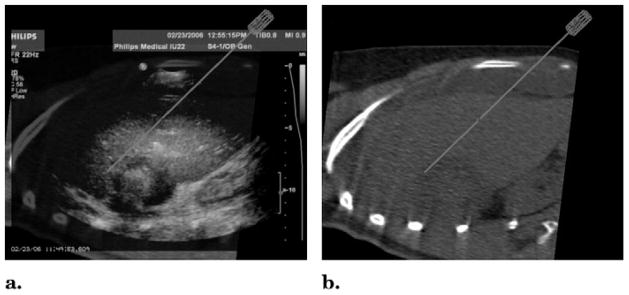
The mean distance between the tracked needle tip and the field generator was 265.3 mm ± 35.3 and was not correlated with the tracking error (P =.26). Fusion of the tracked real-time US and CT images was achieved. Figure 9 shows an example of a real-time US scan with the corresponding MPR in the same location on the preprocedural CT scan.
Figure 9.
(a) Interventional US scan and (b) corresponding multiplanar CT reconstruction calculated and displayed in real time by using a registration based on skin fiducials only. The “virtual” needle, positioned at the edge of the lesion, is superimposed on both images, in the position given by the tracking device and registration transformation. These views can be generated by changing the US transparency in the fusion display depicted in Figure 5.
Tracking Error with Previous Needle Positions
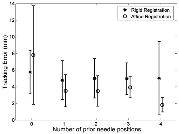
At least one CT-confirmed prior needle position was considered in 18 patients, two or more were considered in 14, three or more were considered in nine, and four or more were considered in two. Figure 10 shows the tracking error as a function of the number of previous needle positions, both for rigid and affine registration transformations. When only skin fiducials were used, the tracking error with affine registration (7.8 mm) was significantly larger than that with rigid registration (5.8 mm). However, with at least one prior needle position, the tracking error with affine registration (3.5 mm) was significantly lower than that with rigid registration (4.8 mm). In addition, both rigid and affine registration with one prior needle position yielded a significantly lower tracking error than did that without a prior needle position.
Figure 10.
Chart shows the tracking error (mean ± standard deviation) as a function of the number of previous needle positions used for the advanced registration method described in the text and in Figure 7.
Semiautomatic Registration with Actively Tracked Fiducials
The data acquisition for each semi-automatic registration took about 2 seconds, compared with 30–40 seconds for each manual needle-based registration. Table 3 summarizes the results in a format analogous to that of Table 1. The corresponding basic tracking error in the same patients with the needle-based registration method was 3.8 mm ± 1.4.
Table 3.
Summary of Results with Automatic Registration with Actively Tracked Skin Fiducials
| Patient No. | No. of Tracked Needle Positions | No. of Active Fiducials | Fiducial Registration Error (mm)* | Basic Tracking Error (mm) |
|---|---|---|---|---|
| 16 | 2 | 8 | 1.7 | 3.3 ± 1.1 |
| 17 | 3 | 6 | 3.2 | 5.2 ± 0.4 |
| 20 | 3 | 5 | 2.4 | 6.0 ± 1.8 |
| Mean ± standard deviation | 2.7 ± 0.6 | 6.3 ± 1.5 | 2.4 ± 0.7 | 5.0 ± 1.5 |
Fiducial registration error using active skin fiducials.
DISCUSSION
A clinical trial was performed to investigate the spatial accuracy of electromagnetic needle tracking in an interventional CT suite. Prior experience with use of internally tracked needles has been reported in swine (23). Compared to the standard procedure used for biopsies and RFA, the modifications necessary to use the tracked needles were minor and did not substantially inhibit the work flow. No complications were seen. Although setup time was recorded in only one patient toward the end of the study, the value is within the mean ± standard deviation of setup times recorded in a subsequent study (n = 17) that used an improved tracking system but followed the same setup procedure.
The basic tracking error of 5.8 mm ± 2.6 is in line with the average tip-to-target errors in a respiratory phantom (6.4 mm) and pig model (8.3 mm) previously reported (23). That study used the same tracking device (NDI Aurora) and a similar setup to the one used here. Our results also compare favorably to a tip-to-target error of 13.2 mm in chest cadavers (27).
The error variation from patient to patient was considerable and can be attributed to a number of factors, including target site, position of the tracked needle relative to the electromagnetic generator and CT table, ability of sedated patients to follow breathing commands, and patient motion. Tracking failed to produce accurate navigation in one patient who was unable to follow breathing commands consistently. Because of the relatively small number of patients, no statistically significant differences were found between different subgroups of the patient population.
A weak negative correlation between tracking error and distance from the CT table was found (P =.08). This is consistent with laboratory evaluations of the Aurora device (28,29), suggesting that a large portion of the basic tracking error can be explained by field distortions introduced by the CT scanner. A newer version of the NDI Aurora tracking device, not used in the current cohort, showed much improved performance in more recent laboratory studies (30).
The use of previous needle positions as additional fiducial markers yielded a considerable and statistically significant reduction in tracking error compared to registrations with skin fiducials only. Field distortions of the electromagnetic tracking system can lead to a complex relationship, including nonuniform scaling and shearing, between the physical coordinates of a tracked device and the tracking coordinates the system is reporting for this device. The scaling and shearing in the affine registration transformation can compensate for part of the field distortions the needle is experiencing. In addition, the previous needle position represents a more recent patient position and/or motion state compared to the skin fiducials, thus compensating in part for patient motion that may have occurred since the preprocedural scan was obtained. When using skin fiducials alone for an affine registration, however, the distortions of the field are sampled in too small a volume, which could explain the significantly larger tracking error when using affine registrations with skin fiducials alone.
Automated registration with use of the actively tracked fiducials showed promise. Simultaneous data acquisition from all sensors speeds up the registration by a factor of 15–20 compared to that with conventional manual needle-based registration. When paired with automatic segmentation of the skin sensors on the preprocedural scan, this scheme may provide fully automatic registrations that require no extra time before needle insertion. However, the tracking error was larger when using the active fiducials compared to the standard registration technique in the same patients. This is likely due to the orientation of the active fiducials parallel to the skin surface, whereas the needle was roughly perpendicular to the skin during registration and needle insertion; these orientation issues are known to affect registration error. Laboratory studies have shown that the tracking error of the system can vary with position and orientation (28,29). A redesign of the active fiducials, with sensors oriented approximately perpendicular to the skin surface, has reduced the error in phantom experiments.
Miniaturization of internalized sensors for electromagnetic tracking of needles and ablation probes has the potential to transform imaging-guided needle-based procedures by providing real-time multimodality feedback. This makes functional use of the exquisite diagnostic images available to today’s radiologist.
Virtual displays of needle position within preprocedural imaging could improve and facilitate thermal ablation by providing position information of targets that would otherwise not be available. This could occur during ablation when gas is released in the heating process, obscuring the US image, or with hypervascular lesions seen only briefly at arterial phase CT, magnetic resonance imaging, or positron emission tomography. The position information can then be used in real time during the procedure instead of trying to guess on needle placements and repositioning by using nearby anatomy or other surrogate spatial information.
US transducer tracking provides a simple method of fusion between US and CT scans and may also be useful during RFA, taking advantage of the real-time feedback from US but using the targeting ability and resolution of CT when US is obstructed by air or bone interfaces or because of gas release during RFA.
Although speculative, other theoretical benefits might include a shorter procedure time, more accurate needle placement, and a smaller radiation dose for the patient. These theoretical benefits must be evaluated in future studies.
It is important to note the limitations of this study. Because the tracking information was not used to guide needle placement, we were unable to specify the overall tracking-assisted placement accuracy relative to that of a preselected target, which would have included the spatial accuracy of the tracking system, the target motion, and the ability of the interventionalist to follow the guidance provided by the tracking system. Further limitations include the small number of patients, the fact that only one physician operator was used, and the variety of procedures and sites.
In conclusion, electromagnetic tracking of needles with internalized sensors may improve US- or CT-guided needle placement, which could have profound implications for imaging-guided tumor ablation. Prospective clinical studies with multiple operators are needed to demonstrate specific clinical benefits.
Acknowledgments
We thank Julia Locklin, RN, MS, for her support in the execution of this study.
This work was supported in part by the Intramural Research Program of the National Institutes of Health Clinical Center and by a Collaborative Research and Development Agreement between the National Institutes of Health and Philips Medical Systems. Clinical Trial Information: ClinicalTrials.gov Identifier: NCT00102544. A full description of this trial can be found at http://www.clinicaltrials.gov/ct/show/NCT00102544?order=1
Abbreviations
- MPR
multiplanar reconstruction
- RFA
radiofrequency ablation
Footnotes
B.J.W., N.G., Philips, and Traxtal have intellectual property in the field. N.G. is the president and a major shareholder of Traxtal. J.K., S.X., J.B., and H.S. are salaried employees of Philips Electronics.
References
- 1.The U.S. image guided and robot-assisted surgery markets. New York: Frost & Sullivan; 2003. Report #A464-54. [Google Scholar]
- 2.Leyendecker JR, Dodd GD., III Minimally invasive techniques for the treatment of liver tumors. Semin Liver Dis. 2001;21:283–291. doi: 10.1055/s-2001-15345. [DOI] [PubMed] [Google Scholar]
- 3.Gazelle GS, Goldberg SN, Solbiati L, Livraghi T. Tumor ablation with radio-frequency energy. Radiology. 2000;217:633–646. doi: 10.1148/radiology.217.3.r00dc26633. [DOI] [PubMed] [Google Scholar]
- 4.Lencioni R, Crocetti L, Cioni D, Della Pina C, Bartolozzi C. Percutaneous radiofrequency ablation of hepatic colorectal metastases: technique, indications, results, and new promises. Invest Radiol. 2004;39:689–697. doi: 10.1097/00004424-200411000-00007. [DOI] [PubMed] [Google Scholar]
- 5.Head HW, Dodd GD., III Thermal ablation for hepatocellular carcinoma. Gastroenterology. 2004;127(suppl 1):S167–178. doi: 10.1053/j.gastro.2004.09.031. [DOI] [PubMed] [Google Scholar]
- 6.Chen MH, Yang W, Yan K, et al. Large liver tumors: protocol for radio-frequency ablation and its clinical application in 110 patients—mathematic model, overlapping mode, and electrode placement process. Radiology. 2004;232:260–271. doi: 10.1148/radiol.2321030821. [DOI] [PubMed] [Google Scholar]
- 7.Dodd GD, III, Napier D, Schoolfield JD, Hubbard L. Percutaneous radiofrequency ablation of hepatic tumors: postablation syndrome. AJR Am J Roentgenol. 2005;185:51–57. doi: 10.2214/ajr.185.1.01850051. [DOI] [PubMed] [Google Scholar]
- 8.Neeman Z, Wood BJ. Radiofrequency ablation beyond the liver. Tech Vasc Interv Radiol. 2002;5:156–163. doi: 10.1053/tvir.2002.36419. [DOI] [PMC free article] [PubMed] [Google Scholar]
- 9.Wood BJ, Abraham J, Hvizda JL, Alexander HR, Fojo T. Radiofrequency ablation of adrenal tumors and adreno-cortical carcinoma metastases. Cancer. 2003;97:554–560. doi: 10.1002/cncr.11084. [DOI] [PMC free article] [PubMed] [Google Scholar]
- 10.McGovern FJ, Wood BJ, Goldberg SN, Mueller PR. Radio frequency ablation of renal cell carcinoma via image guided needle electrodes. J Urol. 1999;161:599–600. [PubMed] [Google Scholar]
- 11.Gervais DA, McGovern FJ, Wood BJ, Goldberg SN, McDougal WS, Mueller PR. Radio-frequency ablation of renal cell carcinoma: early clinical experience. Radiology. 2000;217:665–672. doi: 10.1148/radiology.217.3.r00dc39665. [DOI] [PubMed] [Google Scholar]
- 12.Pautler SE, Pavlovich CP, Mikityansky I, et al. Retroperitoneoscopic-guided radiofrequency ablation of renal tumors. Can J Urol. 2001;8:1330–1333. [PubMed] [Google Scholar]
- 13.Wood BJ. Feasibility of thermal ablation of lytic vertebral metastases with radiofrequency current. Cancer J. 2002;8:26–28. doi: 10.1097/00130404-200201000-00004. [DOI] [PMC free article] [PubMed] [Google Scholar]
- 14.Neeman Z, Patti JW, Wood BJ. Percutaneous radiofrequency ablation of chordoma. AJR Am J Roentgenol. 2002;179:1330–1332. doi: 10.2214/ajr.179.5.1791330. [DOI] [PMC free article] [PubMed] [Google Scholar]
- 15.Patti JW, Neeman Z, Wood BJ. Radiofrequency ablation for cancer-associated pain. J Pain. 2002;3:471–473. doi: 10.1054/jpai.2002.126785. [DOI] [PMC free article] [PubMed] [Google Scholar]
- 16.Dodd GD, Soulen MC, Kane RA, et al. Minimally invasive treatment of malignant hepatic tumors: at the threshold of a major breakthrough. RadioGraphics. 2000;20:9–27. doi: 10.1148/radiographics.20.1.g00ja019. [DOI] [PubMed] [Google Scholar]
- 17.Buscarini E, Savoia A, Brambilla G, et al. Radiofrequency thermal ablation of liver tumors. Eur Radiol. 2005;15:884–894. doi: 10.1007/s00330-005-2652-x. [DOI] [PubMed] [Google Scholar]
- 18.Harvey CJ, Albrecht T. Ultrasound of focal liver lesions. Eur Radiol. 2001;11:1578–1593. doi: 10.1007/s003300101002. [DOI] [PubMed] [Google Scholar]
- 19.Kinkel K, Lu Y, Both M, Warren RS, Thoeni RF. Detection of hepatic metastases from cancers of the gastrointestinal tract by using noninvasive imaging methods (US, CT, MR imaging, PET): a meta-analysis. Radiology. 2002;224:748–756. doi: 10.1148/radiol.2243011362. [DOI] [PubMed] [Google Scholar]
- 20.Fishman JE, Milikowski C, Ramsinghani R, Velasquez MV, Aviram G. US-guided core-needle biopsy of the breast: how many specimens are necessary? Radiology. 2003;226:779–782. doi: 10.1148/radiol.2263011622. [DOI] [PubMed] [Google Scholar]
- 21.Kruecker J, Viswanathan A, Borgert J, Glossop N, Yang Y, Wood BJ. An electro-magnetically tracked laparoscopic ultrasound for multi-modality minimally invasive surgery. Proceedings of CARS 2005, International Congress Series. 1281;2005:746–751. [Google Scholar]
- 22.Wood BJ, Zhang H, Durrani A, et al. Navigation with electromagnetic tracking for interventional radiology procedures: a feasibility study. J Vasc Interv Radiol. 2005;16:493–505. doi: 10.1097/01.RVI.0000148827.62296.B4. [DOI] [PMC free article] [PubMed] [Google Scholar]
- 23.Banovac F, Tang J, Xu S, et al. Precision targeting of liver lesions using a novel electromagnetic navigation device in physiologic phantom and swine. Med Phys. 2005;32:2698–2705. doi: 10.1118/1.1992267. [DOI] [PubMed] [Google Scholar]
- 24.Krueger S, Timinger H, Grewer R, Borgert J. Modality-integrated magnetic catheter tracking for x-ray vascular interventions. Phys Med Biol. 2005;50:581–597. doi: 10.1088/0031-9155/50/4/002. [DOI] [PubMed] [Google Scholar]
- 25.Barry CD, Allott CP, John NW, et al. Three-dimensional freehand ultrasound: image reconstruction and volume analysis. Ultrasound Med Biol. 1997;23:1209–1224. doi: 10.1016/s0301-5629(97)00123-3. [DOI] [PubMed] [Google Scholar]
- 26.Prager RW, Rohling RN, Gee AH, Berman L. Rapid calibration for 3-D free-hand ultrasound. Ultrasound Med Biol. 1998;24:855–869. doi: 10.1016/s0301-5629(98)00044-1. [DOI] [PubMed] [Google Scholar]
- 27.Khan F, Dogan S, Maataoui A, Gurung J, Schiemann M, Vogl TJ. Needle navigation in a true soft tissue environment using the Medarpa system: CT reality superimposed on the site of intervention. Presented at the 91st Scientific Assembly and Annual Meeting of the Radiological Society of North America; Chicago, Ill. November 27 to December 2, 2005. [Google Scholar]
- 28.Shechter G, Shen EB, Stanton D. Measuring and modeling metal artifacts of a CT table on AC electromagnetic tracking system accuracy. Int J Comput Assist Radiol Surg. 2006;1(suppl 1):171–173. [Google Scholar]
- 29.Hummel J, Figl M, Kollmann C, Bergmann H. Evaluation of a miniature electromagnetic position tracker. Med Phys. 2002;29:2205–2212. doi: 10.1118/1.1508377. [DOI] [PubMed] [Google Scholar]
- 30.Hummel J, Figl M, Birkfellner W, et al. Evaluation of a new electromagnetic tracking system using a standardized assessment protocol. Phys Med Biol. 2006;51:N205–210. doi: 10.1088/0031-9155/51/10/N01. [DOI] [PubMed] [Google Scholar]


