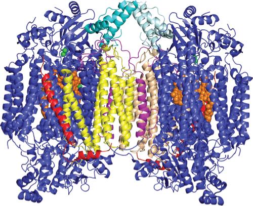
Figure 7.

Three-dimensional structure of dimeric CcO illustrating the location of the four subunits that dissociate during exposure to hydrostatic pressure: yellow and tan for subunit III, magenta for subunit VIa, light and dark teal for subunit VIb, red for subunit VIIa, orange for heme a and a3, and green for CuA and CuB. All other subunits are colored blue. Subunits VIa and VIb are the first subunits to dissociate during pressurization of CcO. In the CcO dimer, both of these subunits are “trapped” at the dimer interface, preventing their dissociation. In monomeric CcO, this constraint is removed, enabling both subunits to dissociate and produce CcO-B, an 11-subunit complex of CcO. Subsequent to the dissociation of subunits VIa and VIb is the dissociation of subunits III and VIIa. Subunit III is located at the dimer interface, and its association is also stabilized by CcO dimerization. This figure was prepared using PyMol (DeLano Scientific LLC, San Francisco, CA) using atomic coordinates of CcO [PDB entry 1v54 (1)].
