

Abstract
The level of hearing rehabilitation enjoyed by cochlear implant recipients has increased dramatically since the introduction of these devices. This improvement is the result of continual development of these systems and the inclusion of subjects with less severe auditory pathology. These developments include advanced signal processing, higher stimulation rates, greater numbers of channels, and the development of more efficient electrode arrays that are less likely to produce insertion damage. New directions in the application of cochlear implants, particularly in combined acoustic and electrical stimulation, and increasing performance expectations will place greater demands on future electrode arrays. Specifically, the next generation of arrays must be reliably inserted without damage, maintain residual acoustic function, and may need to be inserted more deeply.
In this study we measured the mechanical properties of 8 clinical and prototype human cochlear implant electrode arrays and evaluated insertion trauma and insertion depth in 79 implanted cadaver temporal bones. We found that the size and shape of the array directly affects the incidence of observed trauma. Further, arrays with greater stiffness in the plane perpendicular to the plane of the cochlear spiral are less likely to cause severe trauma than arrays with similar vertical and horizontal stiffness.
Keywords: Cochlear implant, Electrode, Trauma, Temporal bone, Electrode array, Design, Insertion depth
Introduction
Cochlear implants (CI) have been used successfully for more than two decades as a rehabilitative aid for severe to profound hearing loss. Over this period the expectation for increased communication capability with these devices has grown dramatically. The earliest cochlear implant recipients reported substantial benefits in lipreading performance and recognition of environmental sounds, but little or no recognition of speech using only the auditory information provided by the implant [1]. As multichannel cochlear implants were introduced, several studies demonstrated that subjects using these devices were capable of discriminating speech without assistance from visual cues. Improvement in CI performance has continued to the present, and many current CI recipients routinely communicate via the telephone and congenitally deaf children who are implanted as infants or toddlers often develop language skills sufficient to allow them to attend mainstream schools. With the dramatic success achieved to date, one might ask what direction future research and development efforts should take to increase the performance of cochlear implants and to benefit subjects with a wider range of hearing impairments?
A cochlear implant operates as an integrated system that includes one or more microphone inputs, a software controlled digital signal processor, a transcutaneous link and an intracochlear stimulating electrode array. In this study we focus on the mechanical design of the electrode array by evaluating five different devices that have been widely implanted in human subjects and three prototype electrode designs to ascertain how specific mechanical properties of each device relate to the incidence of damage.
Three widely accepted goals for the development of future CI electrode arrays include, 1) deeper insertion into the scala tympani to access lower frequency cochlear neurons, 2) greater operating efficiency, defined as a reduction in the stimulus charge required to produce a comfortable loudness level, and 3) reduced intracochlear damage associated with surgical insertion.
Deeper Insertion
CI subject testing and acoustic simulations in hearing subjects have shown that speech recognition is degraded when the frequency bands presented to a listener do not approximate the normal acoustic frequency represented at the cochlear place of stimulation [2-8]. Because the tonotopic locations representing the primary speech formant frequencies are located further along the cochlear spiral, i.e. at lower frequency locations, than most fully inserted implant electrode arrays, it is clear that for most users a significant mismatch occurs between the processed frequency band assigned to each stimulus channel and the cochlear place that it excites. Thus, electrodes with mechanical characteristics that facilitate deeper insertion may be advantageous.
Until recently, determining the optimum depth of insertion and distribution of processed frequency information has been impeded by the lack of an accurate frequency-position map of the human spiral ganglion as well as a clinical method to assess where each CI stimulating site is located in relation to that map in an individual subject. Recent studies have determined the relationship between the progression of characteristic frequencies along the basilar membrane [9] and the comparable frequency vs. position map of neurons in the spiral ganglion [10, 11]. Using a different experimental approach, two recent studies of CI patients with residual hearing compared the pitch percepts produced by stimulation of individual implant channels with percepts produced by acoustic stimulation of varying frequency in the non-implanted ear [12, 13]. Clinical methods to better estimate the frequency location of the implanted electrode array in individual subjects using modern high resolution imaging methods have also been proposed [10, 14]. These anatomical, psychophysical and imaging studies should help to direct the development of electrode arrays and fitting techniques that will result in a more accurate correspondence between the frequency spectra of processed sounds and the location of electrical stimulation.
Increased Efficiency
The efficiency of an intracochlear electrode array is assumed to be highest when each stimulating element is positioned close to the site of neural activation. This site of activation is assumed to be the cell bodies of spiral ganglion neurons or, in some cases, surviving peripheral nerve fibers within the osseous spiral lamina. We also presume that the site of functional neural activation is partly dependent upon the duration of deafness and probably shifts gradually from peripheral dendrites in recently deaf subjects, or those with residual hearing, to the spiral ganglion cell bodies in subjects with the longest history of deafness. In any event, electrode arrays introduced within the past ten years that are designed to position stimulating contacts near the modiolus appear to operate with lower current thresholds than previous devices that were located closer to the lateral wall of the scala tympani [13, 15]. Examples of these perimodiolar electrode arrays include the Cochlear Contour™ and Advanced Bionics HiFocus™ electrode arrays.
Reduced Damage
Trauma to the delicate structures of the inner ear frequently occurs during insertion of cochlear implant electrodes [16-31]. This damage ranges from relatively minor displacement of the basilar membrane to severe fracture of the osseous spiral lamina, tearing of the basilar membrane or spiral ligament and deviation of the electrode path from its intended location in the scala tympani to the overlying scala media and/or scala vestibuli. Even in cases of moderate severity intracochlear trauma may result in reduced numbers of functional peripheral dendrites or spiral ganglion cells, idiosyncratic distribution of these cells and large variation in the efficiency of stimulating sites along the length of the implanted array. In addition, it is possible that damage to the medial surface of the scala tympani, which separates the scala tympani from the internal auditory meatus, might act as a pathway for infection of the central nervous system.
Factors that may affect the incidence of damage include the mechanical properties of a particular electrode design, variations in the size and shape of each cochlea and the specific surgical techniques used for insertion. Because damage to intracochlear structures occurs most frequently to the partition above the scala tympani it has been proposed that an electrode array designed to minimize upward bending might reduce the incidence and severity of insertion related damage [32]. A reduction in the incidence of damage with two electrode arrays that were designed with increased vertical stiffness was reported by Wardrop, et al [16]. However, a more comprehensive evaluation of the mechanical characteristics of a wide range of electrode designs and their possible correlation with insertion damage has not been reported.
Skinner, et al, clearly documented significant variability in the size of the human scala tympani [33] and this variability may be a be an important factor associated with the rate of trauma observed for cochlear implant electrodes with larger cross sectional dimensions [16, 23, 24]. Two current cochlear implant manufacturers, Advanced Bionics, Inc. and Cochlear Corporation, have introduced curved electrodes which utilize an internal stylet to hold the electrode straight during all or part of the insertion process. With both devices the manufacturers recommend that the electrode and stylet be partially inserted into the scala tympani before the electrode is pushed off of the stylet to its full insertion depth. In this process the pre-coiled electrode array returns to a spiral shape intended to facilitate insertion and ultimately position the electrode array near the modiolus. This technique has been termed AOS (Advance Off Stylet). Successful insertion using this procedure requires that the tip of the electrode and stylet be positioned at the beginning of the first cochlear turn prior to pushing the electrode off of the stylet. If the electrode is advanced off of the stylet with the tip positioned too close to the cochleostomy the tightly curved tip of the array may fold back upon itself in the expanded basal cavity of the scala tympani. Conversely, if the straightened electrode and stylet are inserted too far beyond the cochleostomy the electrode tip will contact the outer wall of the first cochlear turn possibly resulting in damage to the spiral ligament or upward penetration into the scala vestibuli.
The implications of insertion trauma for subjects with residual hearing may be even more serious than those for profoundly deaf cochlear implant users, since damage to the organ of Corti could severely affect the transmission and distribution of acoustic vibration along the basilar membrane. The preliminary success of clinical trials with combined electrical and acoustic stimulation highlights the need to develop electrodes that position stimulating contacts close to the modiolus for increased efficiency and that also have the appropriate mechanical features to ensure atraumatic insertion.
Progress to Date
Manufacturers of cochlear implants have addressed these issues in several different ways with varied success. To date, no single design achieves all three objectives of deeper insertion, proximity to the modiolus and consistent atraumatic insertion. The goal of the present study is to measure the physical characteristics of several existing and prototype cochlear implant electrode arrays and to identify specific design features that directly relate to achieving these objectives.
Materials and Methods
In this study 8 different models of electrode arrays were tested in cadaver temporal bones (n=79). Six surgeons participated in the study ranging in experience from those leading large cochlear implant programs with many years of experience to two otology fellows who had recently completed training in otology and specific cochlear implant training equivalent to the device manufacturer’s surgical training course. Each surgeon inserted at least two different electrode array models. The insertion damage observed in previous temporal bone trials with the Cochlear Banded™ (n=8), Cochlear Contour™ (n=18), Spiral Clarion™ (n=8) and HiFocus II™ (with Positioner, n=20)) designs have been previously reported by this laboratory [16, 17]. In this study we have added the mechanical analysis of these previous four electrodes and the temporal bone data and mechanical analysis of four recently tested electrode arrays to permit a broader comparison of the role of electrode mechanical properties and their affect on the occurrence of intracochlear trauma.
Devices Studied
The electrode arrays evaluated in this study include past, current and prototype designs produced by three manufacturers. The specific design and the manufacturer of each array tested are described in Table 1. The Banded™ array, manufactured by Cochlear Ltd. and the Spiral Clarion™, manufactured by Advanced Bionics, are two of the first generation multichannel cochlear implant electrode arrays introduced in the early 1980’s. The Cochlear Banded™ design is a tapered straight electrode 20 mm in length with 22 equally spaced ring contacts. The Spiral Clarion™ electrode array has 16 ball contacts in a spiral-shaped carrier with a length of 16 mm. The contacts are configured as 8 pairs with 2 mm between the center of each pair. One contact of each pair was oriented on the medial side of the electrode carrier toward the position of the spiral ganglion and the second contact was oriented on the upper surface of the carrier toward the osseous spiral lamina or basilar membrane.
Table 1.
Cochlear Implant Electrode Arrays Studied
| Electrode | Manufacturer | Type | ST Pos | # Studied |
|---|---|---|---|---|
| Cochlear Banded™ | Cochlear | Straight | Lateral | N=8 |
| Spiral Clarion™ | Adv. Bionics | Spiral | Mid-scala | N=8 |
| Cochlear Contour™ | Cochlear | Spiral | Perimodiolar | N=18 |
| HiFocus II™ w/Pos | Adv. Bionics | Curved w/Pos | Perimodiolar | N=14 <400° |
| HiFocus II™ w/Pos | Adv. Bionics | Curved w/Pos | Perimodiolar | N=6 >400° |
| Contour Advance™ | Cochlear | Spiral | Perimodiolar | N=3 |
| Nurobiosys | Nurobiosys | Straight | Lateral | N=6 |
| Helix™ | Adv. Bionics | Spiral | Perimodiolar | N=6 |
| Prototype #1 | Adv. Bionics | Spiral | Perimodiolar | N=10 |
The second generation of electrode arrays, the Cochlear Contour™ and Advanced Bionics HiFocus™ II, were designed to increase operating efficiency and channel selectivity by decreasing the distance between the simulating contacts and the spiral ganglion. To accomplish this goal the stimulating contacts on both designs are located on the medial surface of the electrode and two very different strategies are employed to position the electrode closer to the spiral ganglion in situ. The Contour™ array is premolded to a spiral shape and is held on a straight stylet to facilitate insertion. In contrast, the HiFocus II™ electrode was a slightly curved array that was pushed into close proximity to the modious by a separate silicone positioner attached near the tip of the array.
The trauma and insertion depths measured with trial insertions of the Spiral Clarion™ (n=8), HiFocus II™ with positioner (n=20), Cochlear Banded™ (n=8) and original Contour™ (n=18) electrode arrays have been previously reported in detail [16, 17]. These data are summarized in this report and the electrode arrays are further evaluated using the mechanical stiffness measurement techniques described below.
The Contour Advance™ array is an updated version of the Contour™ design which incorporates a more tapered, softer tip and is specifically designed to be inserted using the Advance Off Stylet (AOS) technique.
Three other electrodes examined in this study, the Nurobiosys array and two Advanced Bionics Helix™ designs, are experimental prototypes. The Nurobiosys array is a tapered straight array with 16 ball contacts positioned on the upper surface of the silicone carrier [34]. The Helix™ designs are spiral arrays with 16 medial contacts similar to the Advanced Bionics electrode arrays currently in clinical use.
Insertion Protocol and Histology
Details of the protocol for trial insertions and the histological techniques used in this study have been published previously [17]. In brief, human temporal bones were harvested within 24 hours of death and placed in refrigerated 10% formaldehyde for 24 hours. Following fixation each temporal bone was rinsed in 0.1M phosphate buffer and stored in refrigerated buffer until use. Each temporal bone was prepared by performing a standard surgical approach with posterior tympanotomy. In all cases, the facial recess and facial nerve were preserved to model the realistic surgical constraints present in clinical practice. A 1-2 mm cochleostomy was performed antero-inferior to the round window. In some cases, the stapes was removed and lubricant (50% glycerin in water) was injected into the scala tympani, according to each surgeon’s usual practice. Electrode arrays were inserted via the cochleostomy using the design-specific instruments, if any, supplied by each manufacturer. Each array was inserted to the depth specified by the manufacturer or until resistance was noted by the surgeon.
Following insertion, a plain film radiograph was taken of each implanted temporal bone (see Figure 1). Depth of insertion was estimated from these x-ray images using the coordinate system shown in Figure 1 and previously described by Wardrop, et al [17]. It is important to note that this coordinate system was developed specifically for these temporal bone studies. Recently, several different coordinate systems have been used to describe depth of insertion. In general, if the goal is to estimate the characteristic frequency location for stimulating sites along an electrode array then it is logical that the zero or reference point for measurement should be the beginning of the basilar membrane. For practical purposes this reference point would be the round window in CI subjects evaluated using high resolution CT. However, because the plain film x-ray images used in this study do not permit accurate identification of the RW we have reported insertion depth based on the previous method which defines the 0° reference line as a line through the center of the modiolus parallel to the straight basal segment of the first cochlear turn as shown in Figure 1. To compare insertion depth across studies a correction factor of approximately 30° should be subtracted from the values in this study to derive values comparable to those using the RW as the zero reference.
Figure 1.
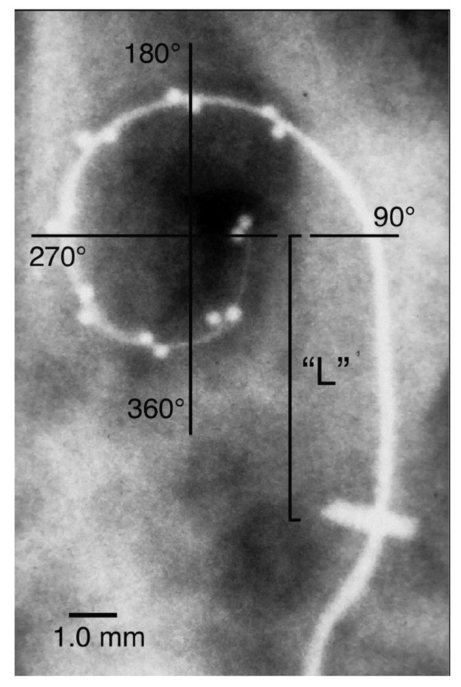
A plain film x-ray image was obtained for each implanted temporal bone. These images were digitized and the insertion angle was measured and tabulated for each electrode array (See text). It is important to note that this coordinate system differs from those of several other studies which define 0° as a line from the central axis of the cochlea through the round window (RW) or other location. In addition, the relatively straight basal segment of each electrode, i.e., from the cochleostomy to the point at which the electrode clearly begins to curve around the cochlear spiral within the basal turn, was measured (“L”).
As described in the introduction, the initial insertion depth of the electrode and stylet, i.e. the depth prior to pushing the array off of the stylet using the AOS technique, may be a critical factor in the incidence of trauma. To measure the variability inherent in estimating this location as a distance from the cochleostomy we measured the distance from the cochleostomy to the beginning of curvature in the first cochlear turn (shown as “L” in Fig. 1).
Next, the bone overlying the cochlea was thinned using cutting and diamond burrs, the specimens were dehydrated and each cochlea was embedded in L.R. White Hard Grade acrylic resin (www.emsdiasum.com) or Epotek 301 epoxy resin (www.epotek.com). Each embedded cochlea was then bisected in the midmodiolar plane using a slow speed saw and diamond slicing blade (www.buehler.com) and the cut surface was polished with aluminum oxide abrasives. In most specimens, a second perpendicular cut was made to separate the cochlea into quarter sections in order to better visualize the full path of the inserted electrode array. Specimens were evaluated using reflected light and transillumination at magnifications ranging from 8 to 45X. For higher resolution images, 0.5 mm thick slices were cut using the diamond saw, polished, stained with Toluidine blue and Basic fuchsin and digitally imaged using a compound microscope with a combination of incident illumination and transillumination. Damage resulting from electrode insertion was recorded for each cochlear section. For the purpose of this study, a specimen was considered to have severe trauma if any portion of the electrode was found to have deviated from the scala tympani into the scala media or scala vestibuli with associated fracture of the osseous spiral lamina, tearing of the basilar membrane or dislocation of the spiral ligament. Figure 2 illustrates an implanted temporal bone prepared by this method.
Figure 2.
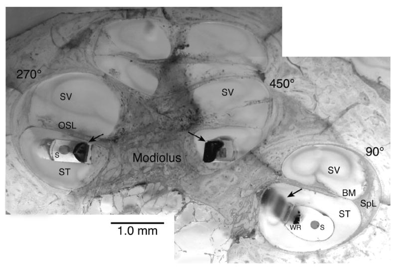
This montage image illustrates a temporal bone implanted with an experimental Advanced Bionics Helix™ electrode, embedded in epoxy resin, cut in the midmodiolar plane and stained with toluidine blue and basic fuchsin. Arrows indicate electrode contact sites. WR = electrode wires, S = Stylet cavity, ST = Scala tympani, SV = Scala vestibuli, SpL = Spiral ligament, BM = Basilar membrane, OSL = Osseous spiral lamina
Scala Tympani Size and Shape
It is clear that the size and shape of an intracochlear array will have a direct effect on the final position of the array within the scala tympani as well as the probability of damage associated with insertion. Several temporal bone studies have shown that insertion of a tapered electrode array may result in severe trauma to the cochlea if the array is inserted past the point where it fills the volume of the ST [16, 23, 24]. However, there are few published reports that systematically describe the cross sectional dimensions or shape of the human scala tympani that can act as a guide in the design of intracochlear arrays. To address this need, measurements of the scala tympani were made in 35 of the embedded cochleae used in this study. Temporal bones were selected for these measurements based on two criteria. First, the margins of the scala tympani must be undamaged and clearly visible to ensure accurate measurement. Second, the plane of section for each specimen must be axial to the modiolus. Even though bones were specifically selected for accurate plane of section we found that it was difficult to maintain axial orientation near the apex of the cochlea. For this reason, cross sections nearer the apex were eliminated if they appeared to be distorted due to an inaccurate plane of section. This resulted in fewer scala tympani outlines being used for measurements in more apical sections.
To create a database of scala tympani dimensions each ST cross section was digitally photographed and the margin of the ST was traced using Canvas™ imaging software to produce a TIFF file. These files were used to generate two outputs. First, to permit analyses of the size, shape and variation of these ST outlines each TIFF file was converted to a mathematical format by determining the mean distance from the centroid of the outline to all boundary pixels within each of 64 angular sectors. Visual comparison of the individual traced outlines with the corresponding reconstructed profiles using this method confirmed that this algorithm reliably and accurately described the shape of each ST. Using these data the mean ST shape for the group of cross sections at each 90° interval was calculated by averaging the distance from the centroid to the profile in each sector and plotting this sector by sector average. To illustrate how this method could be used to design the envelope of a cochlear implant array the sector by sector profile for each ST was used to estimate the largest circle (i.e., maximum circular carrier cross-section) that could lie completely within the ST by using a constrained nonlinear optimization routine (fmincon) in MatLab™ software.
Measurement of Mechanical Properties
Mechanical properties of the electrode array, including stiffness, also affect the insertion characteristics and final position of the array within the scala tympani. The stiffness of each electrode array design was measured using a custom fixture that securely held the array and a mechanical force gauge that measured the force required to flex the array a total of 30° from its normal shape (Figure 3). Stiffness in the vertical and horizontal planes, as defined in the inset in Figure 3, was measured at 1 mm increments from the base of the array to the tip. Within each plane one measurement was made in each direction, i.e. up and down and left and right, and the values measured with two electrode arrays of each design were averaged. The “stiffness ratio” is defined as the ratio of vertical deflection force divided by horizontal deflection force. Because the tip of the electrode array has been reported to be the direct cause of trauma in the majority of specimens in which damage was observed in previous studies [16, 17, 19, 21, 22, 35] the stiffness ratio of the terminal 6 mm of each array was used for statistical correlation with damage and is reported in Table 2.
Figure 3.
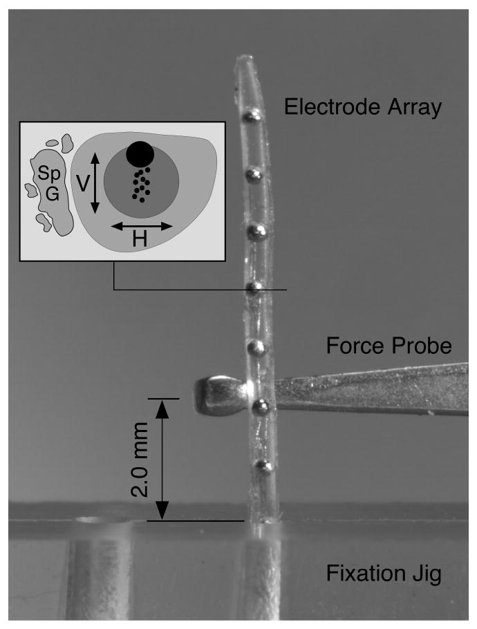
The deflection force required to bend each electrode array 30° at a distance of 2 mm from the fulcrum of a fixation jig was measured with a mechanical force gauge. Deflection force was measured at 1 mm intervals along the length of each electrode in both the horizontal and vertical planes with respect to the intended orientation within the scala tympani (as shown in inset). The data from two electrodes were averaged for each design. The image shown here illustrates the force probe positioned to measure upward deflection force for a straight Nurobiosys electrode array.
Table 2.
Stiffness Measurements, Insertion Damage and Insertion Depth
| Electrode | Vertical Force
(g) |
Horizontal Force
(g) |
Mean Force
(g) |
V/H Force | Trauma Scala Vest. | Mean Depth |
|---|---|---|---|---|---|---|
| Cochlear Banded™ | 0.50 | 0.70 | 0.60 | 0.71 | 37.5% | 285° |
| Spiral Clarion™ | 3.27 | 2.92 | 3.09 | 1.15 | 0% | 445° |
| Cochlear Contour™ | 1.33 | 1.97 | 1.65 | 0.68 | 38.9% | 417° |
| HF II™ w/Pos <400° | 1.29 | 0.47 | 0.88 | 2.77 | 0% | 332° |
| HF II™ w/Pos >400° | 1.29 | 0.47 | 0.88 | 2.77 | 66.6% | 508° |
| Contour Advance™ | 1.33 | 1.97 | 1.65 | 0.68 | 33.0% | 367° |
| Nurobiosys | 1.03 | 0.58 | 0.80 | 1.77 | 0% | 360° |
| Helix™ Exper.#1 | 3.58 | 1.28 | 2.43 | 2.79 | 0% | 390° |
| Helix™ Exper.#2 | 3.29 | 1.23 | 2.26 | 2.67 | 10.0% | 416° |
Results
Dimension of the Scala Tympani
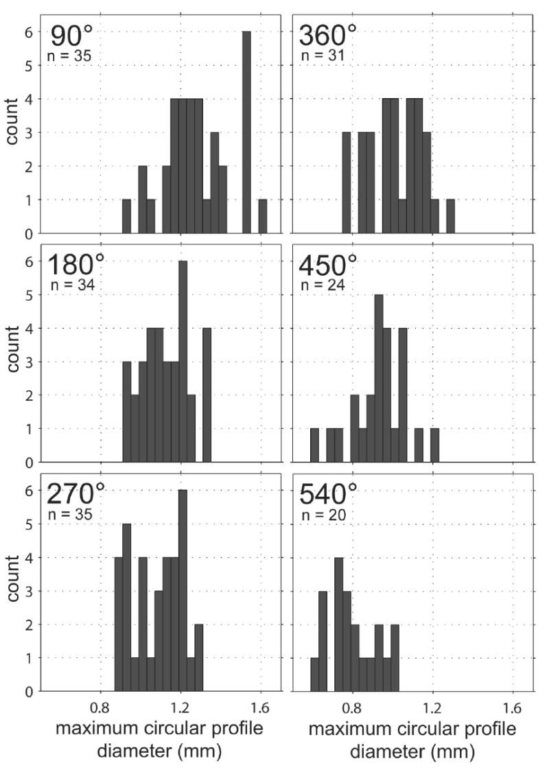
Figure 4a illustrates the range of size and variation in shape observed in cross sections of the human scala tympani. Sections were cut and imaged at intervals of 90° as shown in the inset schematic for each location (lower right corner of each panel). The maximum size of a circular electrode carrier that could be fit in each cross section was calculated using MatLab™ software and tabulated as a frequency histogram in Figure 4b.
Figure 4.
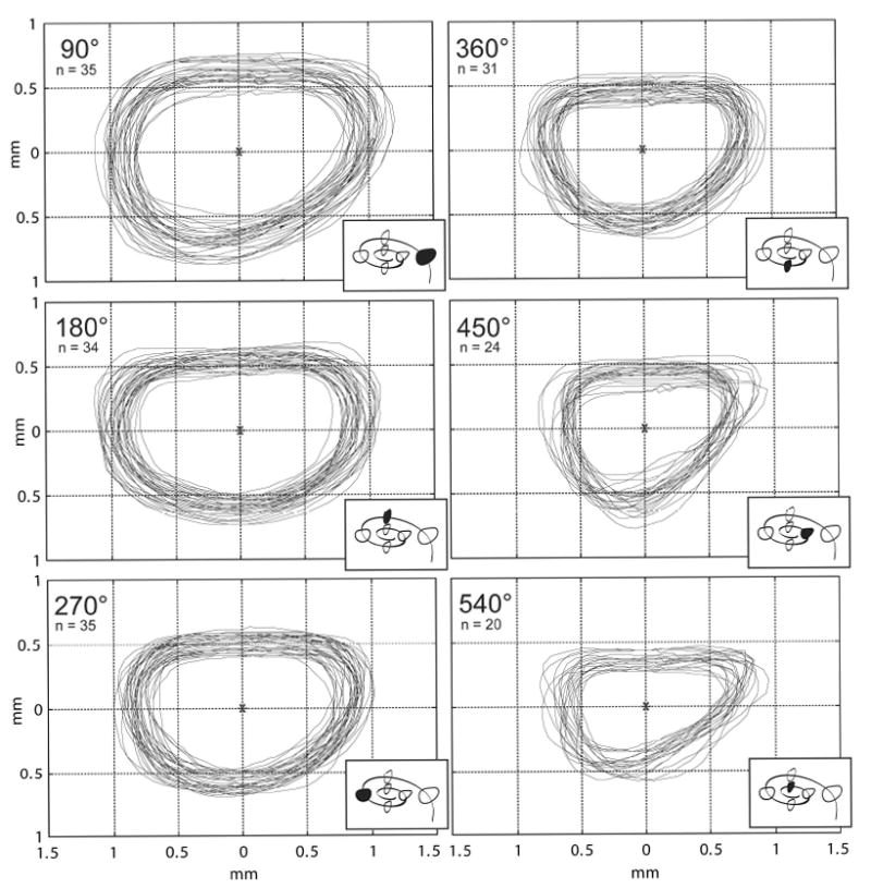
a. Following epoxy embedding, each temporal bone was cut in the mid-modiolar plane (and subsequently each half-cochlea was quartered) and digital images were prepared as shown. Outlines of the scala tympani were traced at 90° intervals (using Canvas™ software) in order to provide an accurate two-dimensional database to evaluate the fit of current and prototype electrode arrays and for use in future cochlear implant design (4a). The group of outlines obtained at each 90° interval were overlaid using the centroid as a reference point to align the profiles. Only specimens without distortion or damage were selected for measurement. For this reason, the number of outlines in the database decreases nearer the cochlear apex.
b. To assist in the design of a cochlear implant electrode array, the maximum diameter of a circular electrode carrier that could fit in each of the cross sections shown in 4a was calculated using MatLab™ software. These diameters are plotted above as frequency histograms for each 90° interval.
For each 90° interval, a mean shape of the scala tympani was obtained by first dividing each outline from Figure 4a into 64 angular sectors and then calculating the average radius in each sector. These mean sector radii were assembled to create a mean ST shape for each interval as shown in Figure 5.
Figure 5.
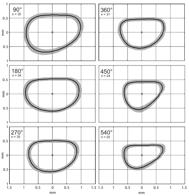
To determine an average shape for the human scala tympani that would be useful as a design tool for future cochlear implant electrode arrays Matlab™ software was used to generate a mean shape for each 90° interval. These mean cross sections are shown as a single dark line surrounded by a gray band in each panel. The gray bands represent one standard deviation larger and smaller than the mean shape.
Advance Off Stylet Insertion
Successful electrode array insertion using the AOS technique requires that the tip of the electrode and stylet be positioned at the beginning of the first cochlear turn prior to pushing the electrode off of the stylet. Thus, it is important to accurately identify this position in the clinical setting. For this purpose, a marker is provided between the 11th and 12th stimulating contact sites on the Contour Advance™ electrode. Using the marker as a guide during initial insertion of the Cochlear Advance™ array, the tip of the electrode is located 9 mm into the cochlea when the marker is adjacent to the cochleostomy. To evaluate how the observed anatomic variation in cochlear dimensions might affect the accuracy of this placement technique we measured the distance from the cochleostomy to the beginning of the first cochlear turn in 62 of these temporal bones. Specimens in which the location of the cochleostomy could not be clearly determined were eliminated for this measurement. This distance (“L” in Figure 1) varied from 4.60 mm to 8.21 mm (mean 6.71 ± 0.82 mm, n=62).
Insertion Damage and Electrode Stiffness
The stiffness and incidence of insertion trauma resulting in deviation of the electrode array from the scala tympani vertically into the scala media or scala vestibuli are summarized in Table 2. It should be noted that no statistically significant difference was seen when we compared the experience of each surgeon with the trauma observed in the temporal bone specimens implanted. Also, the performance of an individual surgeon with one device model did not predict the performance of that surgeon with a different device. For this reason, the results from all surgeons were pooled and results were sorted by electrode array design.
To evaluate the relationship between overall electrode stiffness, differential stiffness ratio (stiffness in the vertical plane divided by stiffness in the horizontal plane) and the resulting insertion damage observed with each electrode design, these factors are plotted in Figures 6 and 7.
Figure 6.
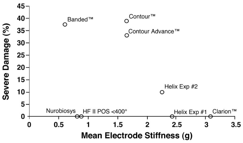
We measured the stiffness of each electrode evaluated in order to correlate specific physical characteristics with the insertion damage observed with each electrode type. In the analysis shown above, the incidence of severe trauma resulting in deviation of the electrode into the scala media or scala vestibuli is plotted as a function of the mean stiffness (average of vertical and horizontal stiffness measurements). The correlation between these two factors was not statistically significant.
Figure 7.
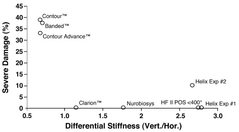
The incidence of severe trauma is plotted as a function of the mean differential stiffness (vertical stiffness/horizontal stiffness) for the apical 6 mm of each electrode design. Electrode arrays with greater stiffness in the vertical plane were less likely to perforate upward into the scala media or scala vestibuli compared to electrodes with isotropic stiffness or greater stiffness in the horizontal plane. This result was statistically significant (p< .01).
No statistically significant relationship was seen between mean electrode stiffness and the incidence of severe trauma. However, the ratio of vertical stiffness divided by horizontal stiffness was significantly correlated with the incidence of trauma (Spearman correlation coefficient = -0.83, p <.01), i.e. proportionally greater vertical stiffness resulted in significantly less damage. Note that for this analysis we excluded the group of Hi Focus II™ electrodes that were inserted beyond 400° because it was clear that the high rate of severe damage observed in this group of specimens was due to the size of the electrode with the attached silicone positioner when inserted too deeply and not to the mechanical characteristics of this device.
Discussion
Electrode Array Size
Several neurophysiological studies have reported response thresholds and distribution of evoked neural activity using individual stimulating contact sites or arrays of stimulating contacts held in silicone carriers [36-39]. These studies examined electrodes with and without insulating carriers, with stimulating contacts in different orientations, and with these contacts in varying proximity to the spiral ganglion. They indicate that one factor directly affecting overall efficacy of stimulation is the use of a relatively large non-conductive carrier. Presumably, the reported differences are the result of multiple factors including reduction in conductive fluid volume surrounding the electrode array and closer positioning of the electrode contacts to the spiral ganglion. From this perspective the use of a space-filling non-conductive carrier or separately introduced positioner would appear to be a positive design attribute. Based on this principle, larger intracochlear electrode arrays such as the Advanced Bionics HiFocus™ array with positioner, and several space-filling prototype arrays were developed.
However, the risk of cochlear trauma during array insertion may be greater with larger volume electrode designs as reported with the HiFocus II™ array with positioner [16, 23, 24]. Non-traumatic implantation requires that the array will not be inserted beyond the depth at which the array will no longer fit within the tapering scala tympani. In general, experienced cochlear implant surgeons have been confident that they were able to perceive an increase in resistance that presumably precedes insertion damage. However, these recent studies have concluded that even when a careful effort was made to stop insertion of the array when resistance was first perceived severe trauma was frequently observed with larger electrodes [16, 23, 24]. Based on these reports it is clear that the possible advantages of a larger volume non-conductive electrode carrier must be balanced against the increased risk of damage associated with such designs. Because of the large variation that exists in ST dimensions it is clear that future intracochlear electrode arrays must be designed to fit all, or almost all, prospective subjects. It is our hope that the detailed scala tympani dimensional data presented in this report (Figures 4 and 5) will be useful as a basis for the effective design of these electrode arrays.
With this concern in mind, alternative methods to mechanically position an electrode array closer to the modiolus, or ideally in gentle contact with the inner wall of the scala tympani, should be considered in future designs. To accomplish this goal most current electrode arrays are molded in a spiral shape designed to match the shape of the modiolar wall. In practice, recent reports illustrate that these arrays are located nearer the center of the scala tympani at many locations along the cochlear spiral. Other approaches might include the ability to change the radius of curvature of the array during or after insertion using shape memory elastomers or metal alloys, pneumatic or fluidic chambers or remotely controlled fibers within the carrier. This “steering” capability might be controlled in real time or pre-programmed. To optimize this capability, location sensors might be included in the tip of the electrode or stylet or along the length of an array.
It is important to note that electrode designs that position the array in contact with the inner (modiolar) wall of the scala tympani may carry increased risk of damage during insertion due to the minimal thickness of this structure or erosion of this thin layer of bone in response to chronic localized pressure. In some areas the inner wall of the scala tympani measures only tens of microns in thickness and represents the only barrier between the fluid filled volume of the cochlea and the cerebrospinal fluid within Rosenthal’s canal, the internal auditory meatus and ultimately the cranial subarachnoid space (See Figure 8). Thus, even minor damage to the modiolar wall may result in loss of spiral ganglion cells due to direct trauma and could also provide a pathway for spread of infection from the middle ear, along the CI carrier and into the cerebrospinal fluid, potentially leading to severe medical complications.
Figure 8.
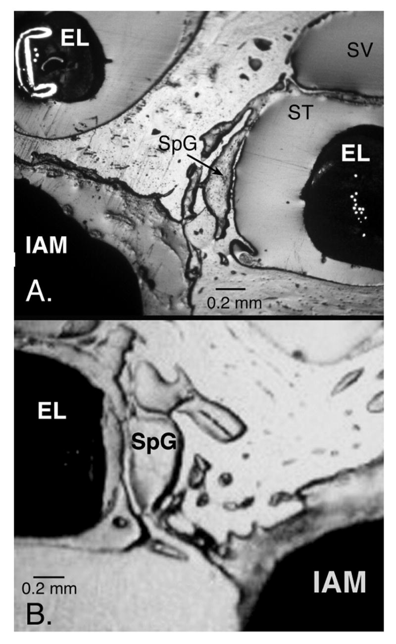
The inner wall of the scala tympani (ST) separates the electrode array from the spiral ganglion cells (SpG) located in the modiolus. These reflected light image of epoxy-embedded human temporal bones implanted with a Cochlear Contour™ electrode (EL in A) and an Advanced Bionics HiFocus II™ electrode with positioner (EL in B) illustrate the thin layer of bone forming this partition and the network of fine channels between the spiral ganglion and the internal auditory meatus (IAM). In the upper image, the basal turn of the cochlea is shown at the right of the image with the second turn above and to the left. Because the bone separating the scala tympani from the IAM is very fragile damage to this partition during electrode insertion is a potential source of serious infection in the CNS.
Insertion Depth
In theory, optimum insertion of a cochlear implant electrode array would result in a range of perceived frequencies that encompass the spectral range of human speech. It seems likely that increasing the range of charateristic frequencies activated by these electrode arrays will result in improved subject performance both in speech recognition and appreciation of music. In addition to the inclusion of a wider spectral range of stimulated frequencies it may also be important to appropriately locate the stimulus frequency bands along the electrode array. Several previously published studies predict that subject performance will improve when the frequency bands of processed speech are delivered to the tonotopically appropriate location in the cochlea [3, 4, 6-8].
Until recently there has been no method to accurately determine the relationship between the physical location of electrode channels in the scala tympani and the tonotopic frequency of the adjacent location in the spiral ganglion. Stakhovskaya and colleagues [10] provide a map of frequency distribution along the length of the spiral ganglion and insights that may be important in future electrode array design.
First, if we assume that the first formant frequencies (F1) for human speech are between 200 Hz and 1,200 Hz, this map indicates that the tip of an ideal electrode array would be located near 540° or 1.5 cochlear turns as measured from the RW. In the present study the mean insertion depth for all electrode designs measured was 391° (approximately 360° measured from the RW) and the mean depth for the perimodiolar electrode designs was 405° (approximately 375° measured from the RW). Thus, we would predict that most subjects using currently available implants experience some decrement in performance due to a mismatch between the frequency band locations assigned to each cochlear implant channel and the tonotopic organization of the spiral ganglion immediately adjacent to these sites.
Second, the length of the spiral ganglion is much less than that of the organ of Corti and the frequency organization of the ganglion is compressed, particularly toward the apex. This compression may make it increasingly difficult to achieve spatial selectivity between apical stimulation channels. Thus, increased channel interaction may explain, at least in part, the results of psychophysical studies that indicate that the performance increase achieved with very deeply inserted electrodes (up to 720°) is minimal for many subjects [40, 41]. In addition, temporal bone studies using deeply inserted electrodes of the same design resulted in a significant increase in trauma compared to moderate depth insertions [25]. Thus, it appears that the potential increase in channel number and lower frequency channel matching that may be attained with electrode insertions beyond 1.5 turns may not result in an overall increase in patient performance.
With these factors in mind, what is the optimal length for a human cochlear implant electrode? It is important to emphasize that the appropriate measure for frequency location and electrode insertion depth in the cochlea is degrees of rotation. This is critical because of the difference in path length between an electrode array located laterally in the scala tympani and one located closer to the modiolus. As an example, the average length of an electrode array required to reach the 400 Hz location is approximately 25 mm for an array located beneath the organ of corti (near the inner edge of the basilar membrane) but only 15 mm for an electrode immediately adjacent to the medial wall [10]. Thus, the optimum length for a cochlear implant array is highly dependent upon the actual position of the array in situ. Using high resolution CT imaging it is now possible to estimate both the size of the cochlea in individual subjects pre-operatively and the depth of insertion for each electrode array post-surgically [14, 33]. This information, used in conjunction with the frequency map developed by Stakhovskaya et al., may be a basis for more accurate assignment of frequency bands to stimulation sites in fitting individual cochlear implant users.
Insertion Damage
As shown in Figure 7 we found that electrode arrays with proportionately greater stiffness in the vertical plane were less likely to produce severe trauma during insertion. There was, however, no correlation between the overall stiffness of the electrode arrays tested and the incidence of damage.
How does electrode array stiffness in the vertical plane affect the incidence of insertion trauma? Figure 9 illustrates insertion of an electrode array into a dimensionally accurate clear model of the human scala tympani [42]. Although most, but not all, current arrays are molded in a spiral shape, they are inserted using a straight stylet and will contact the outer wall of the scala tympani with a large contact angle very similar to that of a straight array. When this contact occurs we hypothesize that an array will deviate either in the horizontal plane, the vertical plane, or both, depending on the bending forces inherent in the electrode array. For example, an electrode with greater vertical stiffness will bend in the horizontal plane following the path of least resistance.
Figure 9.
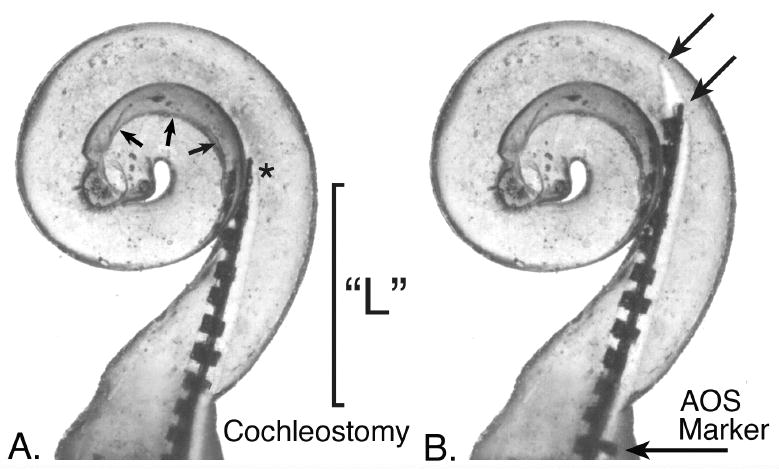
This figure illustrates the initial insertion point for an electrode array and stylet using the AOS (Advance Off Stylet) technique in a dimensionally accurate clear plastic model of the human scala tympani. If the tip of the stylet (*) holding a spiral molded electrode is placed at the point shown in A the electrode array will curve toward the modiolus (small arrows indicate this margin) when it is pushed off of the stylet, thus avoiding contact with the lateral wall and associated damage. However, if the stylet and electrode are overinserted during this initial step, the tip of the electrode and/or stylet (arrows, B) will contact the lateral wall as shown in B. Using this particular replicate model as an example, the marker included on the Contour Advance™ electrode array that is intended to be positioned at the cochleostomy to indicate the correct insertion depth for advancing the electrode array is still approximately 1 mm from that location when the tip of the electrode has contacted the lateral wall. We found that this critical distance (“L” in image A and in Fig. 1.) varied by more than 50% in the specimens measured in this study. We hypothesize that a pre-operative measurement, such as high resolution CT imaging, to estimate this distance might significantly reduce the incidence of insertion trauma using the AOS technique.
In theory, the AOS technique eliminates contact of the pre-curved array with the outer wall of the first turn because the electrode array is pushed off of the stylet before contact occurs and allows the preformed array to curve toward the modiolus as illustrated in Figure 10. However, if the stylet- mounted array contacts the outer wall before the electrode array is advanced off of the stylet, then the contact with the outer wall is not eliminated. As we and others [43] have observed, vertical deflection of the array resulting in penetration of the basilar membrane and/or osseous spiral lamina may still occur using the AOS technique with the latest Cochlear Contour™ array. We hypothesize that trauma may occur more frequently if the tip of the electrode and stylet are inserted too deeply prior to stabilizing the stylet and pushing off the array. We found that accurate estimation of the ideal depth for the stylet tip (shown in Figure 8a and Figure 9) may be difficult in the clinical setting due to large variation in the distance from the cochleostomy site to the beginning of curvature in the first cochlear turn. In the present study, this critical dimension varied by more than 50% of the observed mean value (range = 4.60 mm to 8.21 mm; mean = 6.71 mm, n= 62). We conclude that an accurate method to determine the optimum depth of stylet placement, eg. based on pre-operative imaging in individual patients, can critically reduce the incidence of damage using the AOS technique.
Figure 10.
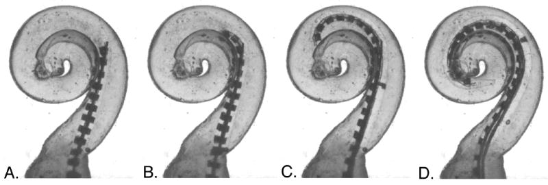
This series of images illustrates the intended insertion of a spiral molded electrode as it is pushed off of a stylet located near the beginning of the first cochlear turn (image A.). Images B-D show the ideal insertion path of a Contour Advance™ electrode array, The tip of the electrode resumes its premolded spiral shape as it is pushed off the straight stylet and avoids contact with the lateral wall. In this particular trial, contact with the inner wall was also minimal. It should be noted, however, that achieving this ideal insertion path requires correct placement depth for the stylet and electrode, and there is currently no specific effort made to accurately determine this location in individual patients prior to implant surgery.
Conclusions
Significant progress in the development of improved cochlear implant electrode arrays has been made during the past decade. The results of this study and others demonstrate that newly developed clinical electrode arrays and experimental prototypes are less likely to produce insertion damage than previous models. However, none of the designs evaluated in this study meet all of the criteria for an ideal cochlear implant electrode— that the electrode be 1) inserted without damage to the cochlea, 2) reliably inserted to a depth of approximately 1.5 cochlear turns (540° as measured from the RW) and 3) be positioned near the modiolus for increased efficiency.
We found that the physical characteristics of different electrode designs strongly affected the incidence of insertion trauma observed with each device. First, electrode arrays with overall dimensions that exceeded the volume of the scala tympani were associated with a high rate of trauma even when the surgeon was careful to stop the insertion at the first sense of resistance. Second, electrode designs with greater stiffness in the vertical plane were generally less likely to produce damage than electrodes that lacked this feature.
In addition to the positive physical characteristics discussed for electrode arrays, we conclude that improvements in surgical methods and insertion instruments are likely to reduce the incidence and severity of trauma during insertion. The rate of damage observed in this study with the Contour Advance™ array was similar to that seen with earlier versions of the Contour™ model. However, it should be noted that the sample size in this group was small (n=3) and that these trial insertions were performed prior to the manufacturer’s introduction of a prototype insertion tool. A recent study, using a larger number of Contour™ electrodes (n=24), reported a lower incidence of trauma with the Contour Advance™ design when applied with the AOS technique both with and without the use of the prototype insertion tool [43]. We note that the traumatic insertions documented with the AOS technique in both studies may be due to the large variability in the critical distance from the round window (or cochleostomy) to the beginning of the first cochlear turn. To date there is no practical method employed to accommodate this variability during clinical insertion although pre-operative high resolution CT imaging may offer a solution to this problem.
Looking to the future, we are hopeful that development of cochlear implant electrodes will continue to progress toward optimized devices that meet all of the criteria discussed in this study. The increasing number of high quality temporal bone studies being conducted to evaluate new electrode arrays is providing direction for this effort. However, the engineering challenges to accomplish these goals, including reliably increasing insertion depth without increasing the occurrence of trauma, are substantial and we anticipate that overcoming these obstacles will require innovative new technology.
Acknowledgments
The authors would like to thank the surgeons, Dr. Lawrance Lustig (UCSF), Dr. William Luxford (House Ear Institute), Dr. J. Thomas Roland Jr.(NYU), and Dr. Jose Fayad (House Ear Institute) for their generous contributions of effort to these studies. We would also like to thank Dr. Jafer Ali, Resident in Otolaryngology at UCSF, for his assistance in procuring and preparing temporal bones for these studies and the device manufacturers for supplying devices for study, technical assistance and their ongoing commitment to collaboratively developing improved cochlear implant electrode arrays and methods to evaluate their progress. These studies were supported by NIH contracts #NO1-DC-3-1006 and NO1-DC-2-1006, HHS-N-263-2007-00064-C and Hearing Research Incorporated. Histological preparation of temporal bone specimens for the Advanced Bionics prototype electrode arrays was supported by Advanced Bionics Incorporated, Sylmar, CA.
Literature Cited
- 1.Bilger RC. Evaluation of patients presently fitted with implanted auditory prosthesis. Ann Otol Rhinol Laryngol. 1977;87(Suppl38):1–176. [Google Scholar]
- 2.Faulkner A. Adaptation to distorted frequency-to-place maps: Implications of simulations in normal listeners for cochlear implants and electroacoustic stimulation. Aud Neurotol. 2006;11(suppl 1):21–26. doi: 10.1159/000095610. [DOI] [PubMed] [Google Scholar]
- 3.Fu QJ, Shannon RV. Effects of electrode configuration and frequncy allocation on vowel recognition with the nucleus-22 cochlear implant. Ear Hear. 1999;20:332–44. doi: 10.1097/00003446-199908000-00006. [DOI] [PubMed] [Google Scholar]
- 4.Fu QJ, Shannon RV, Galvin J. Perceptual learning following changes in the frequency-to-electrode assignment with the nucleus-22 cochlear implants. J Acoust Soc Am. 2002;112:1664–74. doi: 10.1121/1.1502901. [DOI] [PubMed] [Google Scholar]
- 5.Oxenham AJ, Bernstein JGW, Penagos H. Correct tonotopic respresentation is necessary for complex pitch perception. Proc Nat Acad Sci. 2004;101(5):1421–5. doi: 10.1073/pnas.0306958101. [DOI] [PMC free article] [PubMed] [Google Scholar]
- 6.Baskent D, Shannon R. Frequency-place compression and expansion in cochlear implant listeners. J Acoust Soc Am. 2004;116:3130–40. doi: 10.1121/1.1804627. [DOI] [PubMed] [Google Scholar]
- 7.Baskent D, Shannon R. Interactions between cochlear implant electrode insertion depth and frequency-place mapping. J Acoust Soc Am. 2005;117:1405–16. doi: 10.1121/1.1856273. [DOI] [PubMed] [Google Scholar]
- 8.Baskent D, Shannon R. Speech recognition under conditions of frequnecy-place compression and expansion. J Acoust Soc Am. 2003;113(4):2064–76. doi: 10.1121/1.1558357. [DOI] [PubMed] [Google Scholar]
- 9.Greenwood DD. A cochlear frequency-position function for several species - 29 years later. J Acoust Soc Am. 1990;87:2592–605. doi: 10.1121/1.399052. [DOI] [PubMed] [Google Scholar]
- 10.Stakhovskaya O, Sridhar D, Bonham B, Leake PA. Frequency map for the human cochlear spiral ganglion: Implications for cochlear implants. JARO. 2006 doi: 10.1007/s10162-007-0076-9. [DOI] [PMC free article] [PubMed] [Google Scholar]
- 11.Sridhar D, Stakhovskaya O, Leake PA. A frequency-position function for the human spiral ganglion. Aud Neurotol. 2006;11(suppl 1):16–20. doi: 10.1159/000095609. [DOI] [PMC free article] [PubMed] [Google Scholar]
- 12.Boex C, Baud L, Cosendai G, Sigrist A, Kos M, Pelizzone M. Acoustic to electric pitch comparisons in cochlear implant subjects with residual hearing. J Assoc Res Otolaryngol. 2006:1–15. doi: 10.1007/s10162-005-0027-2. Epub. [DOI] [PMC free article] [PubMed] [Google Scholar]
- 13.Dorman M, Spahr A, Gifford R, Loiselle L, McKarns S, Holden T, Skinner M, Finley C. An electric-to-place map for a cochlear implant patient with hearing in the nonimplanted ear. JARO. 2007 doi: 10.1007/s10162-007-0071-1. [DOI] [PMC free article] [PubMed] [Google Scholar]
- 14.Escude B, James C, Deguine O, Cochard N, Eter E, Fraysse B. The size of the cochlea and predictions of insertion depth angles for cochlear implant electrodes. Aud Neurotol. 2006;11(suppl 1):27–33. doi: 10.1159/000095611. [DOI] [PubMed] [Google Scholar]
- 15.Cords SM, Reuter G, Issing PR, Sommer A, Kuzma J, Lenarz T. A silastic positioner for a modiolus-hugging position of intracochlear electrodes: Electrophysiologic effects. Am J Otol. 2000;21:212–17. doi: 10.1016/s0196-0709(00)80011-3. [DOI] [PubMed] [Google Scholar]
- 16.Wardrop P, Whinney D, Rebscher SJ, Luxford W, Leake P. A temporal bone study of insertion trauma and intracochlear position of cochlear implant electrodes. Ii: Comparison of spiral clarion and hifocus ii electrodes. Hear Res. 2005;203:68–79. doi: 10.1016/j.heares.2004.11.007. [DOI] [PubMed] [Google Scholar]
- 17.Wardrop P, Whinney D, Rebscher SJ, Roland JTJ, Luxford W, Leake PA. A temporal bone study of insertion trauma and intracochlear position of cochlear implant electrodes. I: Comparison of nucleus banded and nucleus contour electrodes. Hear Res. 2005;203:54–67. doi: 10.1016/j.heares.2004.11.006. [DOI] [PubMed] [Google Scholar]
- 18.Welling DB, Hinojosa R, Gantz B, Lee J. Insertional trauma of multichannel cochlear implants. Laryngoscope. 1993;103:995–1001. doi: 10.1288/00005537-199309000-00010. [DOI] [PubMed] [Google Scholar]
- 19.Tykocinski M, Saunders E, Cohen LT, Treaba C, Briggs RJS, Gibson P, Clark GM, Cowan RSC. The contour electrode array: Safety study and initial patient trials of a new perimodiolar design. Otol Neurotol. 2001;22:33–41. doi: 10.1097/00129492-200101000-00007. [DOI] [PubMed] [Google Scholar]
- 20.Shepherd RK, Clark GM, Pyman BC, Webb RL. Banded intracochlear electrode array: Evaluation of insertion trauma in human temporal bones. Ann Otol Rhinol Laryngol. 1985;94:55–59. doi: 10.1177/000348948509400112. [DOI] [PubMed] [Google Scholar]
- 21.Richter B, Aschendorff A, Lohnstein P, Husstedt H, Nagursky H, Laszig R. The nucleus contour electrode array: A radiological and histological study. Laryngoscope. 2001;111:508–13. doi: 10.1097/00005537-200103000-00023. [DOI] [PubMed] [Google Scholar]
- 22.Nadol JB, Shiao JY, Burgess BJ, Ketten DR, Eddington DK, Gantz BJ, Kos I, Montandon P, Coker NJ, Roland JT, Shallop JK. Histopathology of cochlear implants in humans. Annals of Otol Rhinol Laryngol. 2001;110:883–91. doi: 10.1177/000348940111000914. [DOI] [PubMed] [Google Scholar]
- 23.Eshraghi AA, Yang NW, Balkany TJ. Comparative study of cochlear damage with three perimodiolar electrode designs. Laryngoscope. 2003;113:415–19. doi: 10.1097/00005537-200303000-00005. [DOI] [PubMed] [Google Scholar]
- 24.Aschendorff A, Klenzner T, Richter B, Kubalek R, Nagursky H, Laszig R. Evaluation of the hifocus™ electrode array with positioner in human temporal bones. Journal of Laryngology and Otology. 2003;117:527–31. doi: 10.1258/002221503322112932. [DOI] [PubMed] [Google Scholar]
- 25.Adunka O, Kiefer J. Impact of electrode insertion depth on intracochlear trauma. Otolaryngol Head Neck Surg. 2006;135:374–82. doi: 10.1016/j.otohns.2006.05.002. [DOI] [PubMed] [Google Scholar]
- 26.Marsh MA, Coker NJ, Jenkins HA. Temporal bone histopathology of a patient with a nucleus 22-channel cochlear implant. Am J Otol. 1992;13:241–48. [PubMed] [Google Scholar]
- 27.Fayad J, Linthicum FH, Otto SR, Galey FR, House WF. Cochlear implants: Histopathologic findings related to performance in 16 human temporal bones. Ann Otol Rhinol Laryngol. 1991;100:807–11. doi: 10.1177/000348949110001004. [DOI] [PubMed] [Google Scholar]
- 28.Fayad JN, Luxford W, Linthicum FH. The clarion electrode positioner: Temporal bone studies. American J Otology. 2000;21:226–29. doi: 10.1016/s0196-0709(00)80013-7. [DOI] [PubMed] [Google Scholar]
- 29.Roland JT, Fishman AJ, Alexiades G, Cohen NL. Electrode to modiolus proximity: A flouroscopic and histologic analysis. Am J Otol. 2000;21:218–25. doi: 10.1016/s0196-0709(00)80012-5. [DOI] [PubMed] [Google Scholar]
- 30.Tykocinski M, Cohen LT, Pyman BC, Roland T, Treaba C, Palamara J, Dahm MC, Shepherd RK, Xu J, Cowan RS, Cohen NL, Clark GM. Comparison of electrode position in the human cohclea using various perimodiolar electrode arrays. Am J Otol. 2000;21:205–11. doi: 10.1016/s0196-0709(00)80010-1. [DOI] [PubMed] [Google Scholar]
- 31.Gstoettner W, Plenk H, Franz P, Hamzavi J, Baumgartner W, Czerny C, Ehrenberger K. Cochlear implant deep electrode insertion: Extent of insertional truama. Acta Otolaryngol. 1997;117:274–77. doi: 10.3109/00016489709117786. [DOI] [PubMed] [Google Scholar]
- 32.Rebscher SJ, Heilmann M, Bruszewski W, Talbot NH, Snyder RL, Merzenich MM. Strategies to improve electrode positioning and safety in cochlear implants. IEEE Trans Biomed Eng. 1999;46:340–52. doi: 10.1109/10.748987. [DOI] [PubMed] [Google Scholar]
- 33.Skinner M, Ketten D, Holden L, Harding G, Smith P, Gates G, Neely J, Kletzker G, Brunsden B, Blocker B. Ct-derived estimation of cochlear morphology and electrode array position in relation to word recognition in nucleus-22 recipients. J Assoc Res Otolaryngol. 2002;3:332–50. doi: 10.1007/s101620020013. [DOI] [PMC free article] [PubMed] [Google Scholar]
- 34.An SK, Park SI, Jun SB, Lee CJ, Sung JH, Oh SH, Wilson BS, Rebscher SJ, Kim SJ. Design for a simplfied cochlear implant system. IEEE Trans Biomed Eng. 2007 doi: 10.1109/TBME.2007.895372. In Press. [DOI] [PubMed] [Google Scholar]
- 35.Chen BK, Clark GM, Jones R. Evaluation of trajectories and contact pressures for the straight nucleus cochlear implant electrode array - a two-dimensional application of finite element analysis. Medical Engineering and Physics. 2003;25:141–47. doi: 10.1016/s1350-4533(02)00150-9. [DOI] [PubMed] [Google Scholar]
- 36.van den Honert C, Stypulkowski PH. Single fiber mapping of spatial excitation patterns in the electrically stimulated auditory nerve. Hearing Research. 1987;29:195–206. doi: 10.1016/0378-5955(87)90167-5. [DOI] [PubMed] [Google Scholar]
- 37.Rebscher SJ, Snyder RL, Leake PA. The effect of electrode configuration and duration of deafness on threshold and selectivity of responses to intracochlear electrical stimulation. J Acoust Soc Am. 2001;109:2035–48. doi: 10.1121/1.1365115. [DOI] [PubMed] [Google Scholar]
- 38.Shepherd RK, Hatsushika S, Clark GM. Electrical stimulation of the audtitory nerve: The effect of electrode position on neural excitation. Hearing Research. 1993;66:108–20. doi: 10.1016/0378-5955(93)90265-3. [DOI] [PubMed] [Google Scholar]
- 39.Snyder RL, Bierer JA, Middlebrooks JC. Topographic spread of inferior colliculus activation in response to acoustic and intracochlear electric stimulation. J Assoc Res Otolaryngol. 2004;5:305–22. doi: 10.1007/s10162-004-4026-5. [DOI] [PMC free article] [PubMed] [Google Scholar]
- 40.Baumann U, Nobbe A. The cochlear implant electrode-pitch function. Hearing Research. 2006;213:34–42. doi: 10.1016/j.heares.2005.12.010. [DOI] [PubMed] [Google Scholar]
- 41.Gani M, Valentini G, Sigrist A, Kos MI, Boex C. Implications of deep electrode insertion on cochlear implant fitting. JARO. 2007;8:69–83. doi: 10.1007/s10162-006-0065-4. [DOI] [PMC free article] [PubMed] [Google Scholar]
- 42.Rebscher SJ, Talbot N, Bruszewski W, Heilmann M, Brasell J, Merzenich MM. A transparent model of the human scala tympani cavity. J Neurosci Meth. 1996;64:105–14. doi: 10.1016/0165-0270(95)00116-6. [DOI] [PubMed] [Google Scholar]
- 43.Stover T, Issing P, Graurock G, Erfurt P, ElBeltagy Y, Paasche G, Lenarz T. Evaluation of the advance off-stylet insertion technique and the cochlear insertion tool in temporal bones. Otol Neurotol. 2005;26:1161–70. doi: 10.1097/01.mao.0000179527.17285.85. [DOI] [PubMed] [Google Scholar]