

Abstract
The unique electronic and optical properties of carbon nanotubes, in conjunction with their size and mechanically robust nature, make these nanomaterials crucial to the development of next-generation biosensing platforms. In this Review, we present recent innovations in carbon nanotube-assisted biosensing technologies, such as DNA-hybridization, protein-binding, antibody-antigen and aptamers. Following a brief introduction on the diameter- and chirality-derived electronic characteristics of single-walled carbon nanotubes, the discussion is focused on the two major schemes for electronic biodetection, namely biotransistor- and electrochemistry-based sensors. Key fabrication methodologies are contrasted in light of device operation and performance, along with strategies for amplifying the signal while minimizing nonspecific binding. This Review is concluded with a perspective on future optimization based on array integration as well as exercising a better control in nanotube structure and biomolecular integration.
1. Introduction
The unique 1D quantum confinement properties of carbon nanotubes (CNTs) have sparked considerable interest in the scientific and technological community.[1–3] CNTs have the potential to revolutionize numerous applications where nano-sized metallic and/or semiconducting components are required along with high strength,[4,5] large flexibility[6] and superb chemical stability.[7,8] In particular, metallic (met-) nanotubes are highly suited for nanoscale circuits,[9] ultrathin, flexible, and transparent conductors,[10] supercapacitors,[11] field emitters,[12] actuators,[13] and nanosized electrochemical probes.[14] Semiconducting (sem-) CNTs on the other hand, are applicable for nanoscale sensors,[15,16] transistors,[17,18] and photovoltaic devices.[19] With diameters similar to or smaller than those of individual proteins, CNTs are expected to serve as high-performance electrical conduits for interfacing with biological systems.[20] Thus, there is enormous interest in utilizing CNTs for biosensor applications, where sensing motifs can be coupled to their optical[21,22] and electronic properties.[23]
The incorporation of carbon nanotubes has the potential to address a variety of long-standing issues with respect to biosensing. In particular, the high surface area of single-walled CNTs (SWNTs), estimated as high as 1600 m2 g−1,[24] while maintaining electrical conductivity is of particular interest to achieve high biomolecule densities suitable for device miniaturization. This is further augmented by the ballistic transport of electrons or holes through SWNTs, with current densities as high as 109 A cm−2 in the presence of oxygen,[18,25] along with prevention of current-induced migration of metal contacts.[26] The facile electron transfer between nanotubes and a variety of protein redox cofactors,[27] in conjunction with conductive polymers[28,29] and nanoparticles[30] of metallic, semiconducting, and magnetic nature provide the means to implement new biosensing schemes and enhance the sensitivity of current methodologies.[27,30,31] CNTs can be readily dispersed as individual[32] and lightly bundled nanotubes[33,34] and assembled,[35] screen-printed,[36] and potentially inkjet-printed to produce device configurations with controlled transparency. This is further amplified by an assortment of covalent and noncovalent functionalization strategies to link a variety of biological entities onto CNTs.[23,37–40] The properties described above, along with excellent potential for device miniaturization, can allow CNTs to be key components of universal sensor platforms, where their unique optical and electronic properties are coupled with biorecognition and enzyme catalysis to enhance functionality.
This Review focuses on the use of CNTs for the electronic and electrochemical detection of enzymes, proteins, and DNA in biosensor formats. First, the electronic and structural properties of CNTs are introduced as they pertain to transistor-based and electrochemical device configuration. Particular attention is given to SWNTs having different metallicity, diameter, and chirality. Next, following a description of various device architectures, this Review will describe successful amplification methodologies for sensitivity enhancement. Future outlook towards sensor miniaturization for array-based applications[41] is also discussed.
2. Carbon Nanotube Properties
The structure of carbon nanotubes can be visualized as the cylindrical roll-up of one or more flat graphene sheets containing carbon atoms in a honeycomb arrangement (Fig. 1).[42] CNTs are typically grown from nanosized metallic particles in the presence of a carbon source at temperatures exceeding 600 °C.[43] Depending on the nature and size of the catalyst as well as the temperature, carbon source, and a variety of processing conditions, nanotubes grow off the metallic nanoparticles as single- or multi-walled carbon nanotubes (SWNTs or MWNTs, respectively). For SWNTs and MWNTs, the diameter ranges from 0.4 to 3 nm and 2 to 100 nm, respectively. Lengths from tens of nanometers to several micrometers are possible by controlling the CNT growth or applying oxidative shortening.[44,45]
Figure 1.
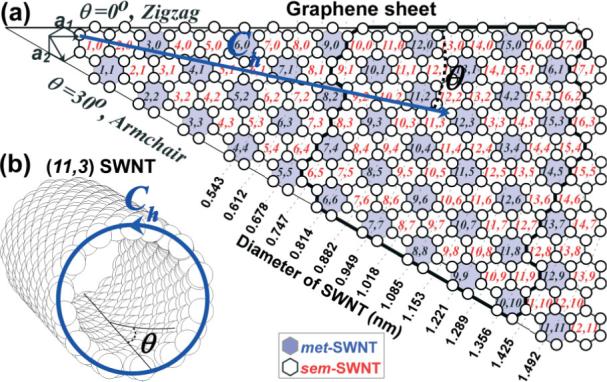
a) Chirality (θ) and diameter (dt) (n, m) map of SWNTs as derived by rolling the Hamada vector (Ch = na1 + ma2) into a circle. a1 and a2 are unit vectors of the graphene sheet constructed by carbon atoms (white circles) in sp2 configuration. b) Representative structure of (11,3) carbon nanotube. White and light shaded cells indicate sem- and met-nanotube character, respectively. The black thick border line indicates the typical (n, m) breadth for HiPco-grown SWNT samples.
The atomically monolayered nanotube surface contains sp2-hybridized carbon atoms. Three out of the four outer-shell electrons of these carbons participate in bonding with neighbor carbons while the fourth electron is in a p-orbital perpendicular to the hexagonal lattice. For an infinite, flat graphene sheet, these p-orbital electrons organize in broad valence (π) and conduction (π*) bands, providing a semi-metallic character owing to their theoretically zero bandgap.[46] This is shown by the dotted lines in the density of states (DOS) versus energy graph of Figure 2a and b. On the other hand, when the graphene sheet is rolled to the cylindrical structure of SWNT, the π and π* electron clouds experience significant curvature, which causes partial σ–π hybridization.[47] This leads to a 1D quantum-confinement structure, where the DOS shows strong dependence on nanotube diameter, chirality, and type (metallic versus semiconducting), as shown in Figure 2.[48–51] As it will become apparent later on in the discussion, the influence of nanotube type, diameter, and chirality plays an important role in high performance electronic, chemo-, and bio-sensing devices.
Figure 2.
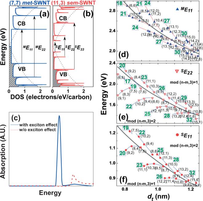
Tight binding calculated DOS versus energy for a) (7,7) met- and b) (11,3) sem-SWNTs. Shaded and white areas indicate the valence band (VB) and conduction band (CB) of SWNTs, respectively. Dotted curves indicate the VB and CB of the planar 2D graphene lattice. The arrows indicate the allowed electronic transitions. c) Calculated absorption profile of a (3,3) SWNT with and without electron–hole interactions, showing the excitonic effect in SWNTs [48]. d–f) Kataura plots for the ME11, SE22 and SE11 transitions as a function of diameter. The different (n, m)-SWNTs are shown classified according to 2n + m family pattern (dotted line and number in square) and modality [mod(n – m,3) = 1 or 2]. Black parabolic curves indicate 1/dt dependence. The ME11 values in (d) were obtained from the theoretical zone-folding scheme [1] based on the Slater–Koster Model [49] with a transfer integral, γo = 2.9 eV [50], while the SE22 and SE11 values in (e,f) were obtained from experimental photoluminescence excitation data [51].
Figure 1a illustrates the Hamada vector (Ch) with respect to the two graphene lattice unit vectors, a1 and a2, shown at the upper left corner. Each nanotube is produced by the circumferential folding of the Ch vector, expressed as the linear combination (Ch = na1 + ma2) of the a1 and a2 unit vectors. The n and m integers are the characteristic pair values for each SWNT.[52] Depending on the pair (n, m) values, SWNTs exhibit either zero bandgap (i.e., metallic for n = m), small bandgap (ca. 10 meV, i.e., semimetallic for n – m = 3k, where k is an integer), or large bandgap (0.6 eV and above, i.e., semiconducting for n – m ≠ 3k).[49,52] Typically, semimetallic tubes are treated as metallic owing to their minute bandgap in relation to room temperature. According to the chirality map of Figure 1a, one third of SWNTs are metallic (light blue hexagons) and two thirds are semiconducting (white hexagons). One thing that stands out from Figure 1a is the plurality of pair (n, m) structures for SWNTs of a given diameter. This is due to the variation in chiral angle (θ), which is defined by the (n, m) pair values according to the following equation: θ = tan−1[31/2m/(m + 2n)].[42] As the nanotube diameter (dt) and diameter distribution increases, the number of different pair (n, m) structures for SWNTs also increases. A typical nanotube sample is a mixture of ca. 50 different (n, m)-SWNTs (i.e., HiP-co SWNTs,[53] shown in Fig. 1a by the thick border enclosure), while the narrowest dt samples contain ca. 20 different (n, m) nanotubes.[54–56]
Figure 2a and b show the DOS versus energy graphs for a representative metallic (7,7)- and semiconducting (11,3)-SWNTs, as calculated from tight-binding theory.[57] The sharp spiked features in both met- and sem-SWNTs DOS are called van Hove singularities. In the case of met-SWNTs, the continuum bridges the valence band (VB, shaded) and conduction band (CB) in the DOS. Sem-SWNTs, on the other hand, exhibit a clear gap between the conduction and valence bands. The van Hove singularities are numbered as i = 1, 2, 3, ..., from the Fermi level (typically in the middle of the valence and conduction bands) and the allowed optical/electronic transitions involve symmetric singularities across the Fermi level (i.e., MEii and SEii for met- and sem-SWNTs, respectively). As shown in Figure 2a and b, the first two semiconducting transitions (SE11 and SE22) fall in between the first metallic transition (ME11). In addition, met-SWNTs in their pristine state contain more electrons near the Fermi-level, as opposed to sem-SWNTs, which renders them more reactive towards a variety of redox reagents.[58]
The simplistic tight-binding model neglects electron–hole or excitonic interactions, which are important in the confined geometry of carbon nanotubes. Recent experimental[59] and theoretical[48] studies have shown that such interactions cause significant differences in the optical transition profiles of SWNTs. Figure 2c shows the calculated absorption profile of a (3,3)-SWNT with and without electron–hole interaction.[48] In the excitonic picture, the majority of the oscillator strength is transferred from the inter-band to the excitonic transitions (sharp lower energy feature in Fig. 2c), which dominates both optical absorption and emission spectra.[48,60] As it turns out, the excitonic effect in SWNTs inflicts significant chirality dependence to the electronic transitions of nanotubes, which imparts large deviations from the 1/dt dependence[61] shown in Figure 2e and f. While the near-arm-chair sem-SWNTs (θ close to 30°) conform to the 1/dt dependence, as the chiral angle gets smaller, a larger deviation from the 1/dt dependence is observed (see Fig. 2d–f). All Eii transitions obey a family (2n + m = constant) pattern (dotted lines) indicated as numbers in the squares in Figure 2d–f. Nanotube modality, which is defined by the remaining integer, either 1 or 2, from the division of the n-m value by 3, also plays an important role in the placement of these Eii transitions.[62,63] For the SE11 transitions, all mod-1 and mod-2 nanotubes are below and above the 1/dt parabolic curves, respectively. This trend is inverse for the SE22 transitions, while for met-SWNTs, this modality dependence is witnessed by the splitting in the van Hove singularities due to warping effects.[57] These family and modality patterns render the electronic transitions of each nanotube different from that of another, and have enabled the scientific community to collectively assign and characterize individual (n, m)-SWNTs via tunable laser resonance Raman spectroscopy (RRS) and photoluminescence excitation (PLE).[56]
These electronic transition differences, however, make SWNT sample homogeneity a major issue. For example, even if a SWNT sample has been separated according to type (met-versus sem-) and dt,[64–70] different chirality and modality nanotubes will contribute significant heterogeneity as the nanotube diameter gets smaller than 1.5−2 nm. This is expected to play a significant role in the reproducibility of advanced nanotube devices as the community continues the refinement in coupling a variety of biological stimuli to SWNT electronic transitions.
3. CNT Characterization
Resonance Raman spectroscopy has been a major tool for (n, m) characterization of SWNTs,[50,71,72] as well as the degree of p- and n-doping[73] and side-wall defects.[74,75] Laser polarization angle-dependent Raman intensity profiling is particularly suited to determine CNT orientation with respect to underlying substrates or nanotube-containing matrices.[76–78] Sem-SWNTs, when dispersed individually with the help of surfactants or other biomolecules, show weak photoluminescence resonant with their electronic transitions.[32,79] Photoluminescence excitation mapping, in conjunction with reconstruction of near-infrared absorption spectrum from the SE11 transition, have recently enabled us to evaluate the semiconducting (n, m)-abundance in a narrow dt SWNT sample.[56,59] Charge-transfer or environmentally induced doping progressively red-shifts and quenches the photoluminescence of sem-SWNTs.[80] Rayleigh scattering,[81] transmission electron microscopy, and electron diffraction[82–84] have been also used for (n, m)-characterization of individualized SWNTs, suspended over a trench to remove interference from the substrate. Scanning-probe microscopy has played a key role for determining CNT length, diameter of nanotube bundles, and features of aggregate organization along with CNT association with biological and nanostructured materials.[85,86] Scanning tunneling microscopy from tip-gated transistor configurations has provided fundamental understanding of the influence of electronic and phononic states to the conductance characteristics of SWNTs.[87,88]
4. Transistor Based Biosensors
Figure 3a and b depicts the two main categories of CNT-based biosensing schemes involving transistor and electrochemical configurations along with device structure and signal-amplification strategies. We begin in this section with nanotube transistor devices. The intrinsic bandgap in the DOS of sem-SWNTs enables them to be used as semiconducting nanosized channels in field-effect transistors (FETs). For MWNTs, the large electronic (met- versus sem-) variability of the concentrically nested nanotubes results in significantly lower abundance of semiconducting-only species. Since the first demonstrations of SWNT-FETs by Dekker[89] and Avouris,[90] where p-type semiconductor FET characteristics were observed for carbon nanotubes, a number of nanotube configurations have emerged for efficient detection of a variety of biomolecules, with detection limits down to picomolar (pm) range.[23,91,92] FET-based biomolecular detection has been termed as “label-free” methodology owing to the fact that it does not employ fluorescence, electrochemical, or magnetic tags.[23,92,93] In reality, the SWNTs in their FET configuration act as “channel modulation label” to sense changes in their immediate environment, as a result of specific interactions between proteins,[23] DNA oligomers,[92] and aptamers.[94]
Figure 3.
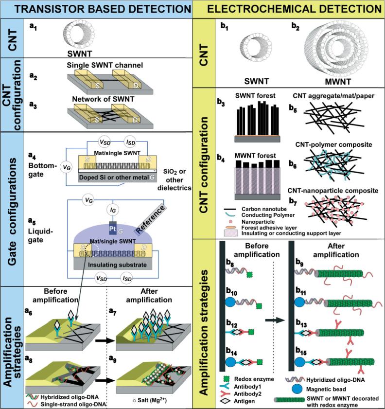
Schematic representation of biomolecular sensing using carbon nanotubes in various device configuration and signal amplification strategies.
Figure 3a illustrates basic SWNT-FET structures with respect to the number of nanotubes spanning the channel (a2 and a3), gate configurations (a4 and a5), and various amplification strategies (a6–a9). Single-nanotube FETs (Fig. 3a2) require the laborious screening of devices incorporating sem-SWNTs as opposed to met-SWNTs. This requirement is removed for the dispersed nanotube network configuration (Fig. 3a3), where the 2 to 1 ratio of sem- to met-SWNTs renders the likely chance of forming a continuous met-SWNT pathway between source (S) and drain (D) improbable.[23,91] Drop casting,[95] dielectrophoresis,[96] and CVD growth[23,91,92,94,97–99] have been employed for the fabrication of dispersed SWNT networks, although the latter approach is gaining greater acceptance owing to the ease of attaining bundle-free structures. Microlithography[92,94,98] and electron beam (e-beam) lithography[97] are typically employed to pattern source and drain contacts, although shadow mask metal evaporation is also used.[23,91]
Figure 3a4 and a5 illustrate the typical gate configurations for SWNT-FET biosensors.[20] The bottom-gate configuration is usually operated under dry conditions following incubation and specific binding of chemical or biological entities onto the transistor channel. The effects of adsorbed biomolecules onto the SWNT-FETs are typically monitored after the removal of weakly bound species via one or more washing steps. Because the measured conductance change is also affected by the non-specifically adsorbed biomolecules, the washing procedure is of great importance. This is a common problem in nearly all binding assays, and termed as “non-specific binding” (NSB).
In the liquid-gate transistor configuration the entire device is immersed and operated in buffer solution, with the nearby Pt electrode held at the desired gate voltage (VG) with respect to source or drain (acting as working electrode). A standard reference electrode has also been used to calibrate the gating potential.[97] For this configuration, interferences arising from the co-existence of solvent media and non-target molecules need to be thoroughly taken into consideration. In addition, the operating voltage regime for liquid-gate SWNT-FETs needs to be confined away from any electrochemical side-reactions. For both gate configurations the current–voltage (I–V) characteristics are typically measured for various gate voltages and converted to conductance values. Alternatively, current changes at fixed gate voltage are monitored and used as detection signal. Figure 4a illustrates a comparison of the source-drain current (ISD) versus VG for both bottom- and liquid-gate configurations.[100] While the general trends are similar, the VG scale for the liquid-gate is significantly narrower than that of bottom-gate arrangement, owing to capacitive differences in these configurations.
Figure 4.
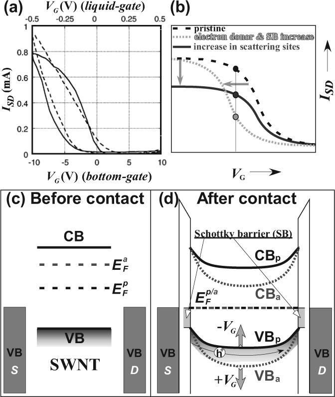
a) SWNT-FET ISD versus VG characteristics for bottom-gate (solid line, bottom x-abscissa) and liquid-gate (broken line, top x-abscissa). (Reproduced with permission from Ref. [100], Copyright 2007, American Chemical Society) b) Typical SWNT-FET ISD versus VG changes originated from biomolecular interactions causing (i) increase in Schottky barrier (SB) or electron donation to SWNTs that shifts to lower threshold VG values or (ii) various perturbations effect that increases the scattering sites and lower the observed saturation ISD current. Simplified band diagrams for before (c) and after (d) source and drain contact with a SWNT in the pristine (p) and amine (a) doped SWNT-FET device configuration. The electron donation from the amine moieties of proteins and/or DNA causes the elevation of SWNT Fermi level and results in greater band bending of both valence (VB) and conduction (CB) bands. For simplicity, detailed metal-SWNT interface states are neglected. The application of positive and negative gate voltages (VG) increase and decrease the band bending, respectively, as indicated by solid up and down arrows. Hole (h+) conduction is also shown as thin solid arrow.
The operation band diagram for a typical SWNT-FET is shown in Figure 4c and d.[101] Prior to outfitting the SWNT with metallic source and drain contacts, the Fermi energies (EF) of the nanotube and that of the metals are not aligned. Following contact with source and drain, the Fermi levels of the SWNT and their metal contacts become aligned. This causes bending of the conduction and valence bands of the nanotube and forms Schottky barriers at the nanotube/metal contacts.[101] Because hole (h+) transport is the dominant conduction pathway in these devices,[90,101] both downward band-bending and the Schottky barrier impede conduction based on the fact that holes prefer to move upwards. A negative VG tends to shift both valence and conduction bands of the SWNT channel upwards (Fig. 4d). This lowers the barrier for hole conduction and results in a source-drain current (ISD) increase, as depicted in Figure 4a. A positive VG further increases band bending and results in a lower ISD. Exposure of the sem-SWNT channel to amines, which typically decorate the outer surface of proteins, raises the Fermi-level from to , where “p” and “a” denote “pristine” and “amine-doped” SWNTs, respectively. Upon contact with the metallic S and D contacts, the amine-exposed nanotube experiences greater downward band-bending as opposed to the pristine nanotube, thereby requiring a more negative VG for the SD channel to be switched on.[16,100] This is schematically shown in Figure 4b, where the exposure of SWNTs to electron donors shifts the threshold VG to more negative values. Similarly, an increase in the Schottky barrier between SWNT and SD contacts will also impart a negative shift to the VG threshold value.[102] Such Schottky barrier variations can originate from work-function fluctuations at the nanotube/metal contacts.[102,103] It has been shown that single-stranded DNA and antibodies bound to the nanotube/metal interface experience structural reorganization when hybridized with complementary DNA and antigens, respectively. Such reorganization induces substantial variations in molecular polarizability and induced dipole moments that tend to shift the work-function of the metal,[102,103] as opposed to the work-function of the nanotube. On the other hand, when the biomolecular adsorbents increase the scattering sites on the nanotubes, carrier mobility decreases and the saturation source-drain current (ISD) values are lowered (see solid blue curve in Fig. 4b).[20]
A typical SWNT-FET binding assay involves initial anchoring of a biological receptor, for example, a nucleotide, aptamer, antibody, or cofactor. This provides recognition sites for target analytes, for example, complementary DNA strand, protein, antigen, or apo-protein. The current–voltage characteristics or conductance of the receptor-modified device are first measured prior to the binding of analytes. In most cases, poly(ethylene glycol)-based surfactants are introduced to minimize nonspecific binding of targets either by covalently linking with receptors or incubating in the surfactant solution prior to the receptor-target recognition step. Finally, the current–voltage characteristics or conductance of the SWNT-FET device is measured following exposure to the analyte.
The observed changes in conductance at a given VG have been attributed to two phenomena: Schottky barrier modulation at the nanotube-metal contact[102,104] and chemical gating at the nanotube channel.[100,105] Dai and Tang performed selective coverage of either SD contacts or the SWNT with a variety of chemical passivating agents. These experiments, in conjunction with quartz crystal microbalance (QCM) measurements, indicate that the majority of source-drain current and conductance changes originate from Schottky barrier modulation at the nanotube/metal contacts as opposed to chemical gating of SWNTs.[100,105] As explained above, the specific binding of complementary DNA or antibody/antigen pairs induces a change in the local dipole moment that raises or lowers the work-function of the metal contacts with respect to the energy levels of the SWNTs, which mostly remain unchanged. This appears to have a profound effect on the Schottky barrier and has been used as means of signal amplification,[91] as described below. This behavior, however, has to be contrasted from small-molecule (such as NH3, NO2) SWNT-FETs sensors,[99] where the intimate adsorption of these analytes onto the large nanotube surface area provides large shifts in the Fermi level of the SWNTs, resulting in substantial valence and conduction band-bending. These intimate interactions are questionable for large biomolecules binding on nanotubes, where the number of functional groups (e.g., amine from lysine moiety) affecting the Fermi level shift of SWNTs is limited.
Typically, microlithographically defined source and drain contacts result in sharp interfaces between the metal electrodes and the nanotubes. This interface is schematically illustrated as a tapered zone in Figure 3a6 and a8, where Schottky barrier modulation of SWNT-FETs takes place.[104] Normally, adsorption of the biomolecular recognition moieties occurs not only onto nanotube sidewalls but also on this tapered-thin metal-SWNT Schottky junction.[102,104] Prior coverage of a Au/SWNT Schottky junction with thiol monolayers, which selectively passivate only the Au surfaces and not the SWNT, prevented binding of the biomolecular receptors from this tapered junction and resulted in minuscule changes in source-drain current and conductance upon introduction of specific-binding targets.[102,104] Angled Au evaporation through a shadow mask produced wide-tapered Schottky junctions, which enabled the immobilization of larger quantities of receptor moieties.[91] This resulted in 100-fold signal amplification and corresponding improvement in target sensitivity (Fig. 3a7). While such amplification has only been demonstrated for two antibody/antigen systems,[91] Tang et al.[102] have shown convincing evidence that this methodology can be extended to DNA hybridization as well. However, one has to be aware that unlike double-stranded DNA,[102] single-stranded DNA adheres strongly onto SWNTs by wrapping around them.[65,106] This renders DNA hybridization less favorable at the SWNT surface as compared to the metal/nanotube Schottky junction,[102] which is schematically shown in Figure 3a8. The introduction of divalent cations (i.e., Mg2+, Co2+, Ca2+, and Hg2+) screens the repulsion between DNA chains and promotes greater adsorption of DNA-oligomers onto this junction.[79] Star et al.[92] have shown that the use of divalent cations results in an increase in sensitivity by three orders of magnitude for SWNT-FET DNA sensors, which is schematically illustrated in Figure 3a9.
Table 1 summarizes recent breakthroughs in SWNT-FET biosensors with respect to their receptor, target, device configuration, detection limit, and signal amplification. By integrating divalent cations and large Schottky contact areas, pM detection limits for DNA hybridization[92] and antibody–antigen binding[23,91] have been achieved. Aptamers (synthetic DNA or RNA strands designed to recognize amino acids, drugs, and proteins) were utilized to detect proteins, such as thrombin[94] and immunoglobulin E.[98] Their smaller size, as compared to protein receptors, was proposed to enhance the band structure changes in SWNT channel or Schottky barrier contact upon binding of analytes. A single sem-SWNT integrated FET was also utilized for detecting the pH changes down to a resolution of 0.1.[97]
Table 1.
Recent SWNT-FET biosensor configuration tabulated against receptor, target, detection limit, and signal amplification.
| Receptor | Target | SWNT configuration | CNT fabrication | SD fabrication | Gate | Detection limit | Signal amplification | Reference |
|---|---|---|---|---|---|---|---|---|
| DNA | DNA | Mat | CVD (Fe) | Ti-Au PhotoL/Evap | Bottom | 1 nM-1 pM | Mg2+ | [92] |
| Antibody (SpA, hCG) | Antigen (IgG, β-hCG) | Mat | CVD (Fe) | Cr-Au Shad-mask/Evap | Liquid | 1pM | SB area increase | [91] |
| Antibody (SpA, BT, U1A) | Antigen (IgG, SP, mAbs) | Mat | CVD (Fe) | Ti-Au Shad-mask/Evap | Liquid | 100 nM-100 pM | N/R | [23] |
| Oligo DNA (possibly RNA) aptamer | Protein (thrombin) | Mat | CVD (Fe, Mo, alumina) | Ti-Au PhotoL/Evap | Liquid | 10 nM | N/R | [94] |
| Oligo DNA (possibly RNA) aptamer vs. Antibody | Antigen (mAb) | Single/few | CVD (Co) | Ti-Au PhotoL/Evap | Liquid | 250 pM (aptamer) >250 pM (antibody) | N/R | [98] |
| Antibody (BT) | Antigen (SP) | Single/few | CVD (Fe) | Ti-Au PhotoL/Evap | Bottom | N/R | N/R | [107] |
| Antibody (anti-CEA) | Antigen (CEA) | Single/few | CVD (Fe, alumina) | Ti-Au PhotoL/Evap | Liquid | 300 fM | N/R | [108] |
| Glucose oxidase | Proton | Single | CVD | Ti-Au e-beamL/Evap | Liquid | pH change of 0.1 | N/R | [97] |
CVD: chemical vapor deposition; PhotoL: photolithography; Evap: evaporation; Shad-mask: shadow mask; e-beamL: e-beam lithography; SB: Schottky barrier; N/R: not reported; SpA: Specific protein A, derived from Staphylococcus aureus; hCG: human chorionic gonadotropin; IgG: rabbit immunoglobulin G; β-hCG: mouse antibody; BT: biotin; SP: streptavidin; U1A: human autoantigen, a prototype target of the autoimmune response in patients with systemic lupus erythematosus and mixed connective tissue disease; mAb: Monoclonal antibody; CEA: carcinoembryonic antigen; anti-CEA: CEA antibody.
5. Amperometric and Voltammetric Biosensors
Bioelectrochemistry encompasses the fundamental study of biomolecule redox chemistry as well as the development of electrochemical biosensors and bioarrays.[109] Over the past decade, a variety of thin film technologies have been developed to facilitate direct electron exchange between electrodes and redox proteins. However, for many important enzymes direct electron transfer with conventional electrodes is not readily achieved or is too slow for sensor applications. This latter class of enzymes includes glucose oxidase, which is used in blood glucose sensors. In commercial glucose sensors, small-molecule or polymer mediators are used to deliver electrons between electrodes and enzymes.[111] Carbon nanotubes can be used as electrodes in conventional electrochemical cells, and can overcome the direct electron transfer barrier for glucose oxidase.[27,112] This has propelled carbon nanotubes into novel and highly sensitive bioamplification strategies.[30,31] Another area in which bioelectrochemistry has made excellent progress is in DNA hybridization sensors for diagnosing genetic diseases.[113–116] As shown below, carbon nanotubes were similarly used to advance this area as well.
There have been two types of approaches to electrochemical biosensors using carbon nanotubes.[37,117,118] In the simplest approach, SWNTs or MWNTs are randomly deposited onto conductive surfaces in a mat configuration (Fig. 3b5), or packed into a micropipette for use as electrodes. The latter method was used by Hill et al. in the first report of nanotube electrodes for bioelectrochemistry, where the reversible cyclic voltammetry (CV) of cytochrome c (cyt c) and blue copper protein azurin adsorbed onto nanotubes was demonstrated.[119] An alternative approach involves SWNT forests, as shown in Figure 3b3.[35] In this configuration, shortened SWNTs are standing vertically, with one end in contact with the underlying electrode and the other end exposed in the electrolyte solution. A number of fabrication methodologies have been developed to afford such SWNT forest configurations using the carboxyl functionalities at the severed ends of nanotubes.[76,78,120,121] These assemblies are realized by the combination of strong substrate–nanotube interactions either by electrostatic SWNT-COO−/Fe3+ interactions[78,122] or carbodiimide-assisted covalent coupling of amine-functionalized substrates with carboxyl-terminated nanotubes.[76,120,121] An important factor for SWNT forest stability is the lateral stabilization via hydrophobic interactions between nanotube walls, forming thick bundles with diameters from 30 to 200 nm. The electrostatic methodology permits, essentially, any flat surface to be functionalized with a SWNT forest with nanotube height varying from 20−250 nm.[123] The assembly process involves sequential substrate dipping in dilute Nafion and aqueous FeCl3 solutions, followed by the slow dimethyl formamide (DMF)-assisted precipitation of the Nafion-adsorbed Fe3+ ions to produce thin FeO(OH)/FeOCl nanocrystals.[122] Subsequent immersion into a DMF dispersed nanotube suspension produces the forest assembly shown in Figure 5a.[75] These versatile, high surface area, patternable nanostructures are uniquely suited for sensitive size-scalable biosensor arrays. Figure 5b shows an atomic force microscopy (AFM) image of a forest with antibodies linked to the carboxyl-functionalized SWNT tips through standard carbodiimide chemistry.
Figure 5.
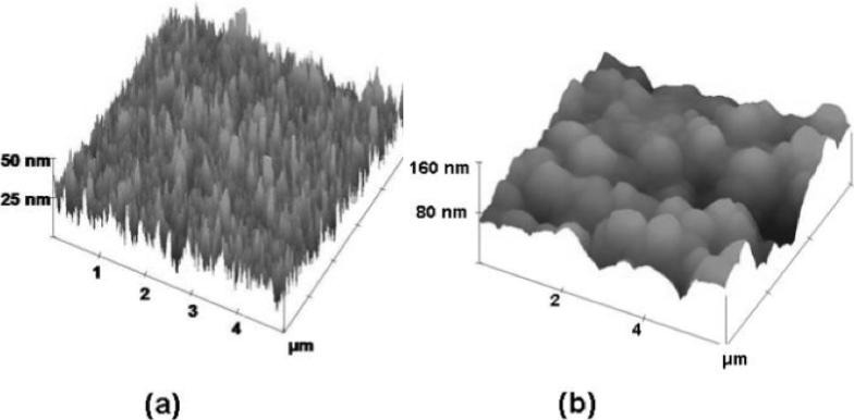
Representative tapping mode atomic force microscopy (AFM) images of a) SWNT forest assembled on Nafion-FeO(OH)/FeOCl functionalized silicon substrate. b) EDC/NHSS coupled HSA antibody on top of SWNT forest assembly. Adapted with permission from Ref. [75], copyright 2005 Royal Society of Chemistry.
Table 2 summarizes the different vertically aligned CNT configurations utilized in biosensor applications as a function of nanotube type, surface coverage, forest height, and hydrodynamic stability. The Nafion-FeO(OH)/FeOCl assembled SWNT forests, reported from our group, exhibits superior surface coverage and hydrodynamic stability. Carbodiimide-based covalent linking of SWNTs to amine-functionalized substrates appears to decrease the SWNT forest coverage by one to two orders of magnitude as compared to the Fe3+-assisted electrostatic assembly. Both methodologies have provided significant advances for electrochemical biosensors through: i) Ease of fabrication using straightforward dipping and washing steps;[78] ii) Flexible patterning schemes;[122] iii) Availability of carboxy-functionality for convenient conjugation with a variety of biomolecules;[31,35,75,124] iv) Convenient SWNT length-fractionation to tune forest height and its resistivity;[123] v) Efficient vectorial electron transfer along the nanotube length with nearby cofactors of enzymes;[35,75] and vi) Excellent hydrodynamic stability at spinning speeds in excess of several thousand rpm.[35] On the other hand, the as-grown single- and multi-walled nanotubes, using chemical vapor deposition (CVD), display much lower surface coverage (107−109 tubes cm−2) and upon drying they may collapse.[125] To overcome this, researchers have first impregnated the nanotube array with either SiO2[125] or polymeric materials[28] and then exposed MWNT tips by electrochemical etching or polishing (Fig. 3b4).
Table 2.
Various methodologies for fabrication of carbon nanotube forests and their respective coverage, height, and hydrodynamic stability.
| Substrate chemistry | CNT type | Surface coverage [tubes cm−2] | Forest height | Hydrodynamic Stability | Reference |
|---|---|---|---|---|---|
| Nafion-FeO(OH)/FeOCl | Carboxy-functionalized SWNTs | 2 × 10¹³ | 30−250 nm | Stable for weeks | [31, 35, 75, 124] |
| Amide-linked alkylthiols on Au | Carboxy-functionalized SWNTs | 1011-1012 | 25−50 nm | Not reported | [27, 45] |
| CVD grown (Fe/Co) | MWNTs | 107-109 | 2−4 μm | Unstable as-grown. Needs support by impregnating with SiO2 or conducting polymers | [28, 125] |
Surface electrocatalysis can be defined as the promotion of electron transfer rates and efficiencies at electrodes. Significant electrocatalysis has been attributed to carbon nanotubes themselves used as electrodes in voltammetry.[37,117,118] The growing research literature on the electrochemistry of small molecules and ions on nanotube electrodes reveals that the degree of electrocatalysis depends on the way the nanotubes are oriented, how much they are oxygenated, and possibly whether they are SWNTs or MWNTs. A recent review by Gooding[118] discusses strong evidence that enhancement of electron transfer rates depends on the amount of surface oxides on the nanotubes that are presented to the reactant. For example, for fast, reversible electron transfer the ideal separation between oxidation and reduction peaks at 25 °C is 59/n mV, where n is the number of electrons per molecule. Such a value was obtained for ferricyanide using SWNT forest electrodes, where the oxygen-functionalized carbon nanotube tips are in direct contact with the solution. However, a much slower electron transfer with oxidation–reduction separation on the order of 100 mV was observed when the shortened SWNTs were arranged in a disordered mat on the underlying electrode surface.[118] Such disordered SWNT mat electrodes present mostly sidewalls, as opposed to oxygenated tips, to the electroactive species. Similar results were obtained with ruthenium hexammine.[118]
Studies with MWNTs have been performed predominantly with nanotubes in the non-oriented mat format. With these electrodes, electrocatalysis was still attributed to the oxygenated tips of the nanotubes.[126] However, when the sidewalls of MWNTs were mainly exposed to the solution, their electrocatalytic activity was similar to that of graphite-based basal plane for several small molecules and ions.[127] To our knowledge, electrocatalysis has not been addressed systematically on MWNT forest electrodes, which present high concentrations of oxygenated nanotube tips to the reactants in solution. We suspect that the disordered nanotube configurations of Figure 3b5–b7 do not take full advantage of the electrocatalytic properties of the oxygenated nanotube tips in the forest organization. Moreover, large inhomogeneities in mat versus forest configurations are expected to also negatively impact current transport.
The above reasons focused our efforts on investigating peroxidases (i.e., myoglobin (Mb) and horseradish peroxidase (HRP)) linked to SWNT forest arrays.[35] Denser SWNT forests resulted in more efficient charge transport through the nanotubes, and nearly all the attached HRP was electroactive.[75] Readily available, glucose oxidase (GOx) has been a popular target for studies with carbon nanotubes because it is a stable enzyme that does not efficiently exchange electrons with most conventional flat electrodes. In the absence of mediators, direct electrochemical interaction with GOx redox cofactor (flavin adenine dinucleotide, FAD) is extremely difficult, since FAD is deeply embedded within the GOx apo-protein.[128] Guiseppi-Elie and co-workers were first to report direct electron exchange between adsorbed GOx and FAD onto unoriented SWNT mats.[112] High temperature annealing (450 °C) of SWNTs was utilized to clean them from various surfactants and promote a more intimate physisorption of GOx onto SWNTs, achieving an electron transfer rate of 1.7 s−1.[112] The covalent linking of GOx onto the tips of vertically aligned MWNT forests further enhanced the electron turnover rate to 1500 s−1.[129] In a more recent study, Willner et al.[27] were able to further increase the electron turnover rate to 4100 s−1 by covalently linking the FAD cofactors to the tips of a SWNT forest. Moreover, a linear correlation of electron transfer rate versus the inverse of SWNT length (1/L) suggested that length-dependent back scattering and nanotube resistance are directly coupled to biocatalysis.
Reversible voltammetry of a number of other redox proteins has been obtained on carbon nanotube electrodes. Gooding et al. used SWNT forest arrays to obtain direct reversible voltammetry of the iron heme protein fragment microperoxidase-11 attached to the ends of the nanotubes.[45] CV of cytochrome c in solution was obtained on SWNT mat electrodes that were electrochemically activated by scanning to extreme voltages.[110] However, peak separations were larger than the reversible limit, and reversibility was inferior to other methods of obtaining cyt c electrochemistry.[109] In another study, oligonucleotide-modified yeast cyt c adsorbed strongly to SWNTs, and gave small reversible voltammograms after background subtraction.[130] A number of other heme proteins have been shown to undergo direct electron exchange with carbon MWNT mat electrodes.[37,117,118] However, except in a few special cases (e.g., glucose oxidase), nanotube mat electrodes do not seem to provide significant advantages in reversibility or signal-to-noise ratio compared to the best redox protein films on conventional electrodes.[109]
Carbon nanotubes have also been used for sensitive bioelectrochemical detection of DNA hybridization.[37,117,131] Examples include Wang's demonstration of zeptomolar detection of DNA obtained by covalently linking thousands of copies of enzyme labels to CNT-conjugated magnetic beads (Fig. 3b11).[30] An average of 9600 alkaline phosphatase (ALP) enzyme moieties were linked on each nanotube and utilized to provide two stages of amplification based on i) number of ALP/nanotube and ii) 20 min catalytic conversion of α-naphthyl phosphate to α-naphthol by ALP. Two additional amplification stages were required to reach such an ultra-sensitive detection limit (ca. 1 fg mL−1 for DNA oligomers) involving iii) magnetic bead concentration of hybridized SWNT/ALP9600 labels onto the working electrode, and iv) the strong absorptive accumulation of the liberated α-naphthol onto MWNT mat-covered working electrode. Here, it is important to stress that the SWNTs or MWNTs used to fabricate the CNT/ALPn labels received extensive oxidation to render them soluble in aqueous media. Besides providing a large number of carboxyl functionalities utilized to immobilize ALP either by covalent linking (EDC coupling)[30] or layer-by-layer electrostatic assembly,[132] this also prevents single-stranded (ss)DNA from wrapping around nanotubes. The latter enables ssDNA, covalently linked to nanotubes, to further hybridize with complementary DNA strands.
6. Amperometric Immunosensors Using SWNT Forests
Significant efforts have been directed toward the design of self-contained electrochemical immunosensors.[133–135] Most of these approaches feature enzyme-linked immunosorbent assay (ELISA) systems built on electrode surfaces. Primary antibodies (Ab1) that capture the antigen (i.e., the analyte) are attached to an electrode surface, so that antigen (Ag) binding, washing, and enzyme label detection are all done on the same surface. Typical electrochemical immunoassays involve competitive and sandwich configurations.
In competitive assays, one starts with an electroactive enzyme-tagged antigen (i.e., Ag-HRP) bound to substrate-attached Ab1 receptors. With the electroactive enzyme tag (i.e., HRP or ALP) catalyzing the redox conversion of a substrate (i.e., H2O2 or α-naphthylphosphate, respectively), the signal produced is proportional to the number of enzyme tags at a fixed substrate concentration.[124] Assuming that the sensing antigen (Ag) has the same binding constant with the electro-active Ag-HRP, the signal reduction from the displacement of Ag-HRP by Ag will be proportional to the concentration of Ag.[134] Competitive assays inherently lack good detection limits owing to the difficulty of accurately measuring the difference between two large signals near the detection limit.
Sandwich immunoassays provide better selectivity and sensitivity.[136] In sandwich assays, a primary antibody (Ab1), attached on the electrode surface first selectively captures the antigen from the sample. Then, a secondary antibody (Ab2) labeled with a redox enzyme (i.e., Ab2-HRP) binds to the antigen (see Fig. 3b12). Sandwich immunoassays are applicable to proteins and bacteria that have large surface areas capable of binding several antibodies at once.[136] The specific binding of the secondary Ab2-HRP to the antigen on the sensor surface turns the Ab1/Ag/Ab2-HRP bioconjugate electro-active. Upon introduction of H2O2 the electroactive bioconjugate will provide a signal proportional to the amount of bound antigen.[134]
Our group has evaluated a number of SWNT forest platforms for amperometric protein immunoassays.[31,75] Figures 3b12 and b13 illustrate single- and multilabel detection strategies using HRP as electroactive label, where the electrode (shown as thick black line) consists of SWNT forest array (Figs. 3b3). This method allows binding and detection on a single surface, with straightforward washing and reagent addition (e.g., labeled antibody) steps performed via dipping or flow modes. Based on this approach, sensitive immunosensors for human serum albumin[75] and prostate specific antigen[31] have been developed, as described below.
Our first amperometric SWNT immunosensor was designed to detect biotin and utilized strong adsorption of antibodies onto SWNT forest assemblies.[124] Using hydroquinone (H2Q) as a soluble mediator, a detection limit of 2.5 pmol mL−1 was reached for HRP-labeled biotin.[124] NSB of biotin-HRP was blocked by washing the sensor with solutions of bovine serum albumin and detergent. This initial study pointed out the importance of decreasing NSB and of using mediators to obtain optimal sensitivity. While mediator-free electron transfer detection of the HRP label was possible, only a fraction of the HRPs attached to biotin communicated with the SWNT forest electrode, compromising sensitivity. This is understandable, because the anti-biotin antibody is placed between biotin-HRP and the nanotube. This brings the distance between HRP and nanotube ends in the range of 5−20 nm, which impedes electrochemical communication. Scheme 1 illustrates the H2Q-assisted electron shuttling from the electrode to the oxidized HRP label. In this simplified pathway, H2O2 oxidizes HRP to the ferryloxy radical form (Eq. 2) which is reduced to ferric HRP by H2Q (Eq. 3). Reduction of quinone (Q) at the electrode (Eq. 1) provides the immunosensor current. Both ferric-HRP and Q are regenerated in this catalytic pathway.
Scheme 1.
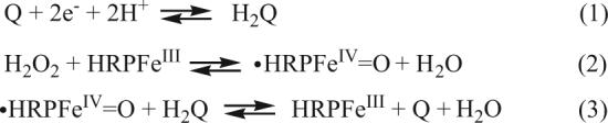
Pathway for mediated electrochemical detection of HRP labels.
Proof-of-concept for sandwich immunoassays on SWNT forest assemblies was demonstrated using human serum albumin (HSA).[75] For the unmediated case, a detection limit of 75 pmol mL−1 (75 nm) was obtained for HSA. For sandwiched Ab1/Ag/Ab2-HRP assays, the efficiency for direct electron exchange suffers more, because the average distance between HRP labels and nanotube ends is even larger than in the competitive immunosensor configuration. This can be easily overcome by electron mediation. Hydroquinone mediation improved the HSA detection limit (defined as the concentration where signal is three times that of noise) by 75-fold down to 1 pmol mL−1 (1 nm). In terms of sensor sensitivity (defined as the slope of amperometric current versus analyte concentration), H2Q mediation enabled 10 000-fold improvement versus mediator-less immunoassays. In addition, through a series of controls, it was proven that SWNT forest increased the mediated amperometric signal versus that of planar electrodes by 10- to 16-fold.
This electrochemical immunoassay was then applied to real biomedical samples.[31] For this, we chose prostate-specific antigen (PSA), an established biomarker for diagnosing and monitoring prostate cancer.[137,138] PSA was the first cancer biomarker to see wide clinical use, and has been employed for 20 years. It can appear in a “danger zone” of 4−10 ng mL−1 in patient serum up to 5 years before clinical signs of disease, illustrating the usefulness and predictive ability of such biomarker measurements in early cancer detection. Figure 6a illustrates the correlation of PSA detection in human serum samples from cancer and cancer-free patients, measured with single-labeled (Ab2-HRP) SWNT forest sandwich immunoassay versus a standard enzyme-linked immunosorbent assay (ELISA).[31] The one-to-one correlation of the two techniques with respect to direct and standard addition tests (obtained by adding three aliquots of standard PSA serum and extrapolation to determine the unknown PSA concentration) indicates the very promising future of SWNT forest electrochemical immunoassays for reliable point-of-care diagnostics of cancer and other diseases.
Figure 6.
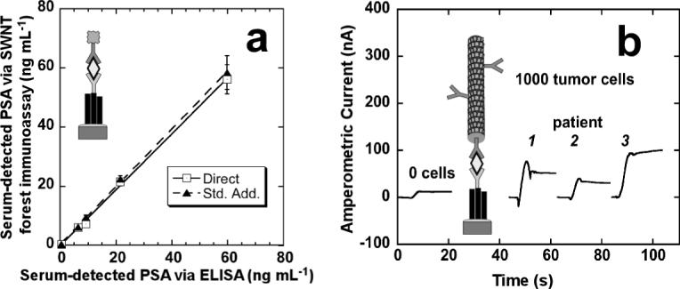
a) Correlations of SWNT forest/Ab1/Ag/Ab2-HRP electrochemical immunoassay for PSA (Ag) in human serum samples found by using direct comparison to a calibration curve (□) and by standard addition (σ) against results from a standard ELISA determination (RSD ± 10%) for the same samples. b) Amperometric current obtained from amplified immunoassay at −0.3 V versus Ag/AgCl and 3000 rpm in which the working electrodes were incubated with prostate tissue lysates from 1000 cells in 10 μL buffer for 1.25 h followed by 10 μL anti-PSA-MWNT-HRP90 bioconjugate (11 pmol mL−1 in HRP) in 0.05 % Tween-20 for 1.25 h. Reproduced with permission from Ref. [31], copyright 2007 American Chemical Society.
To further boost detection sensitivity from miniscule amounts of tissue or from very low concentrations in serum, an amplification step was incorporated by combining SWNT forest immunosensors with HRP-MWNT-Ab2 bioconjugates with high HRP/Ab2 ratios (see Fig. 3b13). For this, the secondary antibody (Ab2) and HRP tag were covalently linked by amidization to heavily carboxylated MWNTs at the mixing ratio of 1:200.[31] This amplification strategy improved the detection limit 100-fold and the sensitivity by 800-fold, compared to using the conventional Ab2-HRP. The measured PSA detection limit was 4 pg mL−1 in 10 μL serum (100 amol mL−1), or a mass detection limit of 40 fg. The 100-fold enhancement in detection limit using HRP-MWNT-Ab2 bioconjugate versus the Ab2-HRP case is in good agreement with the number of HRPs per MWNT, estimated at ca. 90. Using this very sensitive approach, it was possible to quantitatively measure PSA in lysates from 1000 laser-dissected prostate tissue cells from frozen human tissue sections (Fig. 6b).[31] These results indicate that the CNT-supported multi-HRP/Ab2 tags show excellent promise for ultrasensitive immunoassay research in proteomics and systems biology.
7. Future Outlook and Concluding Remarks
The examples discussed above clearly demonstrate the excellent promise of CNT-based transistors and electrochemical biosensors as valuable future tools for biomedical diagnostics and research. For electrochemical biosensors, it is our view that ordered nanotube arrays exemplified by SWNT forests will be necessary to obtain the best sensitivities and detection limits. Realizing the full potential of these nanotube biodevices will require their fabrication into individually addressable arrays for multiplexed biomolecule determinations. Such devices will be readily adaptable to modern biomedical areas such as genomics, proteomics, cancer diagnostics, and metabolomics. Promising milestones include the 3-transistor arrays developed by Lieber et al.,[93] and nanotube forests[112] and mats[139] reported on gold arrays.
A relevant practical test has been passed for single SWNT immunosensors by detection of PSA in human serum and tissue.[31] The detection limit of 4 pg mL−1 for PSA in real samples is better than existing commercial immunoassays.[31] SWNT immunosensors can be adapted easily for detection of other relevant biomarkers, as well as bacteria and other biopathogens. Moreover, their potential for array-multiplexing should provide affordable biochip fabrication for simultaneous measurement of multiple biomarkers. This is expected to significantly increase the success rate and accuracy for early cancer prediction.[136,140–142] We believe that SWNT array devices have a very promising future for reliable point-of-care diagnostics of cancer and other diseases. They also have other potentially important applications in proteomics, metabolomics, and systems biology.
In the SWNT-FET biosensors, two technical issues have to be resolved to further miniaturize and multiplex these devices. First, the underlying biodetection mechanism needs to be thoroughly understood. Experiments involving selective passivation of CNTs and/or source-drain electrodes, in conjunction with properly designed biological entities, are crucial for differentiating between the nanotube-metal Schottky barrier and SWNT chemical gating models. Especially, the effect of functional groups in proteins and DNA need to be contrasted to that of small molecules, such as amines. Moreover, the electronic properties of both CNTs and the Schottky contact before and after exposing to biomolecules can be topologically investigated by using techniques such as scanning gate microscopy and Kelvin force microscopy.[143,144] Second, the persistent 1/f noise issue,[145,146] where the noise in SWNT-FET electrical signals, such as source-drain voltage, fluctuates proportional to 1/fα (0 < α < 2), needs to be resolved to acquire ultralow detection limits in miniaturized SWNT-FET biosensors.
Advances in the SWNTs growth,[54,55] etching[147] and separation[64–70] processes could further improve nanotube-uniformity in terms of removing metallic SWNTs. Sem-enriched SWNTs with defined (n, m) chirality can be engineered to have their Eii transitions lined up appropriately with either the thin metal-plasmon resonance or the redox levels of analyte under investigation to further enhance sensitivity. Improving our understanding on how to orient and bring closer various biomolecules to SWNTs is also important. For mat-SWNT-FET configuration, significant effort also needs to be exerted to ensure electrical similarity between all contacts among individual nanotubes. Moreover, by increasing the density of sem-only SWNTs within the FET channel, one can suppress 1/f noise and improve detection limits.
Contrary to SWNT-FET biosensors, where sem-SWNTs are crucial for optimum device performance, electrochemical detection from nanotube forest arrays might be improved further by utilizing met-enriched nanotubes. Similarly, improving conductivity in multi-tagged nanotubes could further improve performance. Last but not least, creative approaches in incorporating magnetic amplification strategies to concentrate analyte onto working electrodes are expected to significantly advance the current biodetection limit.[30] In addition, gaining a greater insight on how to control and further minimize non-specific binding for multiple biomarkers could ultimately propel array immunosensors through commercialization.
Biographies
 Sang Nyon Kim received his B.E. degree in Industrial Chemistry from Kyungpook National University (Daegu, Korea) in 1999 and his M.Sc. degree in Chemistry from the Korea Institute of Science and Technology (Daejeon, Korea) in 2001. He is presently a Ph.D. candidate at the laboratory of Professor Papadimitrakopoulos at the Institute of Materials Science at the University of Connecticut. His research focuses on nanomaterial-based biodetection and single-walled carbon nanotubes separation according to their diameter and metallicity.
 Dr. James F. Rusling was born in 1946 in Philadelphia. He was awarded a B.Sc. in Chemistry at Drexel University and a Ph.D. in Chemistry from Clarkson University. In 1979, he joined the faculty of the University of Connecticut, where he is currently Professor of Chemistry and Professor of Pharmacology (Health Center). His research interests are in biocatalysis, and developing sensor arrays for cancer biomarker detection and genotoxicity prediction. He has authored over 250 refereed research papers, a book on chemical and biochemical data analysis, and has edited two research monographs. He is also a musician who plays traditional Irish and American music on accordion, guitar, banjo and harmonica in several bands.
 Dr. Fotios Papadimitrakopoulos was born in Athens, Greece in 1965. He received his B.Sc. in Chemistry from the University of Athens, Greece (1987) and his M.Sc. and Ph.D. from the Polymer Science & Engineering Department at the University of Massachusetts in 1989 and 1993, respectively. After a two-year postdoctoral stay at AT&T Bell Laboratories, he joined the faculty of the University of Connecticut where he is currently Professor of Chemistry as well as the Associate Director of IMS. With “self-organization” as a common theme, he has established a diverse research program that spans over the separation of single-walled carbon nanotubes (SWNTs) by length, type, and diameter, SWNT biosensors, implantable glucosensors, quantum dots for intracellular trafficking, DNA-assembly of colloidal microspheres for photonic crystal applications and organic light emitting/photovoltaic devices. He has co-authored more than 100 peer-reviewed publications, has given more than 100 invited presentations, and has co-organized 7 International Conferences. In 2004, he was elected member of the Connecticut Academy of Science and Engineering.
Footnotes
This work has been supported in part by PHS grant ES013557 from NIEHS/NIH, U.S. Army Research Office (ARO) grant DAAD-02-1-0381, AFSOR FA9550-06-0030 and US Army Medical Research Grant W81XWH-05-1-0539, and NSF DMI 0303950. The authors wish to thank Drs. J. Silvio Gutkind and Vyomesh Patel of the National Institute of Dental and Craniofacial Research for collaboration in biomarker detection, Dr. P. Pehrsson of Naval Research Laboratory for stimulating discussions and Mr. Bhaskara Chikkaveeraiah for technical assistance.
Contributor Information
Sang Nyon Kim, Institute of Materials Science, University of Connecticut Storrs, CT 06269.
James F. Rusling, Institute of Materials Science, University of Connecticut Storrs, CT 06269 (USA) E-mail: james.rusling@uconn.edu Department of Chemistry, University of Connecticut Storrs, CT 06269 (USA) Department of Pharmacology, University of Connecticut Health Center Farmington, CT 06032 (USA)
Fotios Papadimitrakopoulos, Institute of Materials Science, University of Connecticut Storrs, CT 06269 (USA) E-mail: papadim@mail.ims.uconn.edu Department of Chemistry, University of Connecticut Storrs, CT 06269 (USA) Department of Pharmacology, University of Connecticut Health Center Farmington, CT 06032 (USA).
References
- 1.Saito R, Dresselhaus G, Dresselhaus MS. Physical Properties of Carbon Nanotubes. Imperial College Press; London: 1998. [Google Scholar]
- 2.Dresselhaus MS, Dresselhaus G, Eklund PC. Science of Fullerenes and Carbon Nanotubes. Academic; San Diego: 1996. [Google Scholar]
- 3.Dai H. Acc. Chem. Res. 2002;35:1035. doi: 10.1021/ar0101640. [DOI] [PubMed] [Google Scholar]
- 4.Gao G, Cagin T, Goddard WA., III Nanotechnology. 1998;9:184. [Google Scholar]
- 5.Yu M-F, Files BS, Arepalli S, Ruoff RS. Phys. Rev. Lett. 2000;84:5552. doi: 10.1103/PhysRevLett.84.5552. [DOI] [PubMed] [Google Scholar]
- 6.Zhang M, Atkinson KR, Baughman RH. Science. 2004;306:1358. doi: 10.1126/science.1104276. [DOI] [PubMed] [Google Scholar]
- 7.Sotiropoulou S, Chaniotakis NA. Anal. Bioanal. Chem. 2003;375:103. doi: 10.1007/s00216-002-1617-z. [DOI] [PubMed] [Google Scholar]
- 8.Zhou W, Vavro J, Guthy C, Winey KI, Fischer JE, Ericson LM, Ramesh S, Saini R, Davis VA, Kittrell C, Pasquali M, Hauge RH, Smalley RE. J. Appl. Phys. 2004;95:649. [Google Scholar]
- 9.Yao Z, Kane CL, Dekker C. Phys. Rev. Lett. 2000;84:2941. doi: 10.1103/PhysRevLett.84.2941. [DOI] [PubMed] [Google Scholar]
- 10.Wu Z, Chen Z, Du X, Logan JM, Sippel J, Nikolou M, Kamaras K, Reynolds JR, Tanner DB, Hebard AF, Rinzler AG. Science. 2004;305:1273. doi: 10.1126/science.1101243. [DOI] [PubMed] [Google Scholar]
- 11.An KH, Kim WS, Park YS, Choi YC, Lee SM, Chung DC, Bae DJ, Lim SC, Lee YH. Adv. Mater. 2001;13:497. [Google Scholar]
- 12.Fan S, Chapline MG, Franklin NR, Tombler TW, Cassell AM, Dai H. Science. 1999;283:512. doi: 10.1126/science.283.5401.512. [DOI] [PubMed] [Google Scholar]
- 13.Baughman RH, Cui C, Zakhidov AA, Iqbal Z, Barisci JN, Spinks GM, Wallace GG, Mazzoldi A, De Rossi D, Rinzler AG, Jaschinski O, Roth S, Kertesz M. Science. 1999;284:1340. doi: 10.1126/science.284.5418.1340. [DOI] [PubMed] [Google Scholar]
- 14.Burt DP, Wilson NR, Weaver JMR, Dobson PS, Macpherson JV. Nano Lett. 2005;5:639. doi: 10.1021/nl050018d. [DOI] [PubMed] [Google Scholar]
- 15.Li J, Lu Y, Ye Q, Cinke M, Han J, Meyyappan M. Nano Lett. 2003;3:929. [Google Scholar]
- 16.Kong J, Franklin NR, Zhou C, Chapline MG, Peng S, Cho K, Dai H. Science. 2000;287:622. doi: 10.1126/science.287.5453.622. [DOI] [PubMed] [Google Scholar]
- 17.Appenzeller J, Knoch J, Derycke V, Martel R, Wind S, Avouris P. Phys. Rev. Lett. 2002;89:126801/1. doi: 10.1103/PhysRevLett.89.126801. [DOI] [PubMed] [Google Scholar]
- 18.Heinze S, Tersoff J, Martel R, Derycke V, Appenzeller J, Avouris P. Phys. Rev. Lett. 2002;89:106801/1. doi: 10.1103/PhysRevLett.89.106801. [DOI] [PubMed] [Google Scholar]
- 19.Kymakis E, Alexandrou I, Amaratunga GAJ. J. Appl. Phys. 2003;93:1764. [Google Scholar]
- 20.Gruener G. Anal. Bioanal. Chem. 2006;384:322. doi: 10.1007/s00216-005-3400-4. [DOI] [PubMed] [Google Scholar]
- 21.Cherukuri P, Bachilo SM, Litovsky SH, Weisman RB. J. Am. Chem. Soc. 2004;126:15638. doi: 10.1021/ja0466311. [DOI] [PubMed] [Google Scholar]
- 22.Barone PW, Baik S, Heller DA, Strano MS. Nat. Mater. 2005;4:86. doi: 10.1038/nmat1276. [DOI] [PubMed] [Google Scholar]
- 23.Chen RJ, Bangsaruntip S, Drouvalakis KA, Kam NWS, Shim M, Li Y, Kim W, Utz PJ, Dai H. Proc. Natl. Acad. Sci. USA. 2003;100:4984. doi: 10.1073/pnas.0837064100. [DOI] [PMC free article] [PubMed] [Google Scholar]
- 24.Cinke M, Li J, Chen B, Cassell A, Delzeit L, Han J, Meyyappan M. Chem. Phys. Lett. 2002;365:69. [Google Scholar]
- 25.Wei BQ, Vajtai R, Ajayan PM. Appl. Phys. Lett. 2001;79:1172. [Google Scholar]
- 26.Baughman RH, Zakhidov AA, de Heer WA. Science. 2002;297:787. doi: 10.1126/science.1060928. [DOI] [PubMed] [Google Scholar]
- 27.Patolsky F, Weizmann Y, Willner I. Angew. Chem. Int. Ed. 2004;43:2113. doi: 10.1002/anie.200353275. [DOI] [PubMed] [Google Scholar]
- 28.Gao M, Dai L, Wallace GG. Electroanalysis. 2003;15:1089. [Google Scholar]
- 29.Luo X, Killard AJ, Morrin A, Smyth MR. Anal. Chim. Acta. 2006;575:39. doi: 10.1016/j.aca.2006.05.064. [DOI] [PubMed] [Google Scholar]
- 30.Wang J, Liu G, Jan MR. J. Am. Chem. Soc. 2004;126:3010. doi: 10.1021/ja031723w. [DOI] [PubMed] [Google Scholar]
- 31.Yu X, Munge B, Patel V, Jensen G, Bhirde A, Gong JD, Kim SN, Gillespie J, Gutkind JS, Papadimitrakopoulos F, Rusling JF. J. Am. Chem. Soc. 2006;128:11199. doi: 10.1021/ja062117e. [DOI] [PMC free article] [PubMed] [Google Scholar]
- 32.O'Connell MJ, Bachilo SM, Huffman CB, Moore VC, Strano MS, Haroz EH, Rialon KL, Boul PJ, Noon WH, Kittrell C, Ma J, Hauge RH, Weisman RB, Smalley RE. Science. 2002;297:593. doi: 10.1126/science.1072631. [DOI] [PubMed] [Google Scholar]
- 33.Liu J, Casavant MJ, Cox M, Walters DA, Boul P, Lu W, Rimberg AJ, Smith KA, Colbert DT, Smalley RE. Chem. Phys. Lett. 1999;303:125. [Google Scholar]
- 34.Furtado CA, Kim UJ, Gutierrez HR, Pan L, Dickey EC, Eklund PC. J. Am. Chem. Soc. 2004;126:6095. doi: 10.1021/ja039588a. [DOI] [PubMed] [Google Scholar]
- 35.Yu X, Chattopadhyay D, Galeska I, Papadimitrakopoulos F, Rusling JF. Electrochem. Commun. 2003;5:408. [Google Scholar]
- 36.Wang J, Musameh M. Analyst. 2004;129:1. doi: 10.1039/b313431h. [DOI] [PubMed] [Google Scholar]
- 37.Katz I, Willner I. ChemPhysChem. 2004;5:1084. doi: 10.1002/cphc.200400193. [DOI] [PubMed] [Google Scholar]
- 38.Britzab DA, Khlobystov AN. Chem. Soc. Rev. 2006;35:637. [Google Scholar]
- 39.Bianco A, Kostarelos K, Prato M. Curr. Opin. Chem. Biol. 2005;9:674. doi: 10.1016/j.cbpa.2005.10.005. [DOI] [PubMed] [Google Scholar]
- 40.Bianco A, Kostarelos K, Partidos CD, Prato M. Chem. Commun. 2005:571. doi: 10.1039/b410943k. [DOI] [PubMed] [Google Scholar]
- 41.Patolsky F, Zheng G, Lieber CM. Anal. Chem. 2006;78:4260. doi: 10.1021/ac069419j. [DOI] [PubMed] [Google Scholar]
- 42.Dresselhaus MS, Eklund PC. Adv. Phys. 2000;49:705. [Google Scholar]
- 43.Charlier J-C, Iijima S. Top. Appl. Phys. 2001;80:55. [Google Scholar]
- 44.Liu J, Rinzler AG, Dai H, Hafner JH, Bradley RK, Boul PJ, Lu A, Iverson T, Shelimov K, Huffman CB, Rodriguez-Macias F, Shon Y-S, Lee TR, Colbert DT, Smalley RE. Science. 1998;280:1253. doi: 10.1126/science.280.5367.1253. [DOI] [PubMed] [Google Scholar]
- 45.Gooding JJ, Wibowo R, Liu J, Yang W, Losic D, Orbons S, Mearns FJ, Shapter JG, Hibbert DB. J. Am. Chem. Soc. 2003;125:9006. doi: 10.1021/ja035722f. [DOI] [PubMed] [Google Scholar]
- 46.Painter GS, Ellis DE. Phys. Rev. B. 1970;1:4747. [Google Scholar]
- 47.Blase X, Benedict LX, Shirley EL, Louie SG. Phys. Rev. Lett. 1994;72:1878. doi: 10.1103/PhysRevLett.72.1878. [DOI] [PubMed] [Google Scholar]
- 48.Spataru CD, Ismail-Beigi S, Benedict LX, Louie SG. Phys. Rev. Lett. 2004;92:077402. doi: 10.1103/PhysRevLett.92.077402. [DOI] [PubMed] [Google Scholar]
- 49.Saito R, Fujita M, Dresselhaus G, Dresselhaus MS. Appl. Phys. Lett. 1992;60:2204. [Google Scholar]
- 50.Jorio A, Saito R, Hafner JH, Lieber CM, Hunter M, McClure T, Dresselhaus G, Dresselhaus MS. Phys. Rev. Lett. 2001;86:1118. doi: 10.1103/PhysRevLett.86.1118. [DOI] [PubMed] [Google Scholar]
- 51.Weisman RB, Bachilo SM. Nano Lett. 2003;3:1235. [Google Scholar]
- 52.Hamada N, Sawada S, Oshiyama A. Phys. Rev. Lett. 1992;68:1579. doi: 10.1103/PhysRevLett.68.1579. [DOI] [PubMed] [Google Scholar]
- 53.Chiang IW, Brinson BE, Huang AY, Willis PA, Bronikowski MJ, Margrave JL, Smalley RE, Hauge RH. J. Phys. Chem. B. 2001;105:8297. [Google Scholar]
- 54.Bachilo SM, Balzano L, Herrera JE, Pompeo F, Resasco DE, Weisman RB. J. Am. Chem. Soc. 2003;125:11186. doi: 10.1021/ja036622c. [DOI] [PubMed] [Google Scholar]
- 55.Chen Y, Ciuparu D, Lim S, Yang Y, Haller GL, Pfefferle LD. J. Catal. 2004;225:453. [Google Scholar]
- 56.Luo Z, Pfefferle LD, Haller GL, Papadimitrakopoulos F. J. Am. Chem. Soc. 2006;128:15511. doi: 10.1021/ja0657096. [DOI] [PubMed] [Google Scholar]
- 57.Saito R, Dresselhaus G, Dresselhaus MS. Phys. Rev. B. 2000;61:2981. [Google Scholar]
- 58.Strano MS, Dyke CA, Usrey ML, Barone PW, Allen MJ, Shan HW, Kittrell C, Hauge RH, Tour JM, Smalley RE. Science. 2003;301:1519. doi: 10.1126/science.1087691. [DOI] [PubMed] [Google Scholar]
- 59.Bachilo SM, Strano MS, Kittrell C, Hauge RH, Smalley RE, Weisman RB. Science. 2002;298:2361. doi: 10.1126/science.1078727. [DOI] [PubMed] [Google Scholar]
- 60.Perebeinos V, Tersoff J, Avouris P. Phys. Rev. Lett. 2004;92:257402. doi: 10.1103/PhysRevLett.92.257402. [DOI] [PubMed] [Google Scholar]
- 61.Kataura H, Kumazawa Y, Minami N, Umeza I, Suzuki S, Ohtsuka Y, Kazaoui S, Achiba Y. Synth. Met. 1999;103:2555. [Google Scholar]
- 62.Reich S, Thomsen C, Robertson J. Phys. Rev. Lett. 2005;95:077402. doi: 10.1103/PhysRevLett.95.077402. [DOI] [PubMed] [Google Scholar]
- 63.Oyama Y, Saito R, Sato K, Jiang J, Samsonidze GG, Gruneis A, Miyauchi Y, Maruyama S, Jorio A, Dresselhaus G, Dresselhaus MS. Carbon. 2006;44:873. [Google Scholar]
- 64.Chattopadhyay D, Galeska I, Papadimitrakopoulos F. J. Am. Chem. Soc. 2003;125:3370. doi: 10.1021/ja028599l. [DOI] [PubMed] [Google Scholar]
- 65.Zheng M, Jagota A, Strano MS, Santos AP, Barone P, Chou SG, Diner BA, Dresselhaus MS, Mclean RS, Onoa GB, Samsonidze GG, Semke ED, Usrey M, Walls DJ. Science. 2003;302:1545. doi: 10.1126/science.1091911. [DOI] [PubMed] [Google Scholar]
- 66.Chen Z, Du X, Du M-H, Rancken CD, Cheng H-P, Rinzler AG. Nano Lett. 2003;3:1245. [Google Scholar]
- 67.Krupke R, Hennrich F, von Lohneysen H, Kappes MM. Science. 2003;301:344. doi: 10.1126/science.1086534. [DOI] [PubMed] [Google Scholar]
- 68.Kim SN, Luo Z, Papadimitrakopoulos F. Nano Lett. 2005;5:2500. doi: 10.1021/nl051840k. [DOI] [PubMed] [Google Scholar]
- 69.Arnold MS, Stupp SI, Hersam MC. Nano Lett. 2005;5:713. doi: 10.1021/nl050133o. [DOI] [PubMed] [Google Scholar]
- 70.Arnold MS, Green AA, Hulvat JF, Stupp SI, Hersam MC. Nat. Nanotechnol. 2006;1:60. doi: 10.1038/nnano.2006.52. [DOI] [PubMed] [Google Scholar]
- 71.Kuzmany H, Plank W, Hulman M, Kramberger C, Gruneis A, Pichler Th., Peterlik H, Kataura H, Achiba Y. Eur. Phys. J. B. 2001;22:307. [Google Scholar]
- 72.Luo Z, Papadimitrakopoulos F, Doorn SK. Appl. Phys. Lett. 2006;88:073110/1. [Google Scholar]
- 73.Rao AM, Eklund PC, Bandow S, Thess A, Smalley RE. Nature. 1997;388:257. doi: 10.1126/science.275.5297.187. [DOI] [PubMed] [Google Scholar]
- 74.Huang H, Marie J, Kajiura H, Ata M. Nano Lett. 2002;2:1117. [Google Scholar]
- 75.Yu X, Kim SN, Papadimitrakopoulos F, Rusling JF. Mol. Bio-Syst. 2005;1:70. doi: 10.1039/b502124c. [DOI] [PubMed] [Google Scholar]
- 76.Diao P, Liu Z, Wu B, Nan X, Zhang J, Wei Z. ChemPhysChem. 2002;3:898. doi: 10.1002/1439-7641(20021018)3:10<898::AID-CPHC898>3.0.CO;2-U. [DOI] [PubMed] [Google Scholar]
- 77.Duesberg GS, Loa I, Burghard M, Syassen K, Roth S. Phys. Rev. Lett. 2000;85:5436. doi: 10.1103/PhysRevLett.85.5436. [DOI] [PubMed] [Google Scholar]
- 78.Chattopadhyay D, Galeska I, Papadimitrakopoulos F. J. Am. Chem. Soc. 2001;123:9451. doi: 10.1021/ja0160243. [DOI] [PubMed] [Google Scholar]
- 79.Heller DA, Jeng ES, Yeung T-K, Martinez BM, Moll AE, Gastala JB, Strano MS. Science. 2006;311:508. doi: 10.1126/science.1120792. [DOI] [PubMed] [Google Scholar]
- 80.O'Connell MJ, Eibergen EE, Doorn SK. Nat. Mater. 2005;4:412. doi: 10.1038/nmat1367. [DOI] [PubMed] [Google Scholar]
- 81.Sfeir MY, Wang F, Huang L, Chuang C-C, Hone J, O'Brien SP, Heinz TF, Brus LE. Science. 2004;306:1540. doi: 10.1126/science.1103294. [DOI] [PubMed] [Google Scholar]
- 82.Zuo JM, Vartanyants I, Gao M, Zhang R, Nagahara LA. Science. 2003;300:1419. doi: 10.1126/science.1083887. [DOI] [PubMed] [Google Scholar]
- 83.Hashimoto A, Suenaga K, Gloter A, Urita K, Iijima S. Nature. 2004;430:870. doi: 10.1038/nature02817. [DOI] [PubMed] [Google Scholar]
- 84.Sfeir MY, Beetz T, Wang F, Huang L, Huang XMH, Huang M, Hone J, O'Brien S, Misewich JA, Heinz TF, Wu L, Zhu Y, Brus LE. Science. 2006;312:554. doi: 10.1126/science.1124602. [DOI] [PubMed] [Google Scholar]
- 85.Odom TW, Hafner JH, Lieber CM. Top. Appl. Phys. 2001;80:173. [Google Scholar]
- 86.Poggi MA, Bottomley LA, Lillehei PT. Anal. Chem. 2002;74:2851. doi: 10.1021/ac025695w. [DOI] [PubMed] [Google Scholar]
- 87.Freitag M, Radosavljevic M, Zhou Y, Johnson AT, Smith WF. Appl. Phys. Lett. 2001;79:3326. [Google Scholar]
- 88.LeRoy BJ, Kong J, Pahilwani VK, Dekker C, Lemay SG. Phys. Rev. B. 2005;72:075 413. [Google Scholar]
- 89.Tans SJ, Devoret MH, Groeneveld RJA, Dekker C. Nature. 1998;394:761. [Google Scholar]
- 90.Martel R, Schmidt T, Shea HR, Hertel T, Avouris P. Appl. Phys. Lett. 1998;73:2447. [Google Scholar]
- 91.Byon HR, Choi HC. J. Am. Chem. Soc. 2006;128:2188. doi: 10.1021/ja056897n. [DOI] [PubMed] [Google Scholar]
- 92.Star A, Tu E, Niemann J, Gabriel J-CP, Joiner CS, Valcke C. Proc. Natl. Acad. Sci. USA. 2006;103:921. doi: 10.1073/pnas.0504146103. [DOI] [PMC free article] [PubMed] [Google Scholar]
- 93.Zheng G, Patolsky F, Cui Y, Wang WU, Lieber CM. Nat. Biotechnol. 2005;23:1294. doi: 10.1038/nbt1138. [DOI] [PubMed] [Google Scholar]
- 94.So H-M, Won K, Kim YH, Kim B-K, Ryu BH, Na PS, Kim H, Lee J-O. J. Am. Chem. Soc. 2005;127:11906. doi: 10.1021/ja053094r. [DOI] [PubMed] [Google Scholar]
- 95.Onoa B, Zheng M, Dresselhaus MS, Diner BA. Phys. Status Solidi A. 2006;203:1124. [Google Scholar]
- 96.Taeger S, Sickert D, Atanasov P, Eckstein G, Mertig M. Phys. Status Solidi B. 2006;243:3355. [Google Scholar]
- 97.Besteman K, Lee JO, Wiertz FGM, Heering HA, Dekker C. Nano Lett. 2003;3:727. [Google Scholar]
- 98.Maehashi K, Katsura T, Kerman K, Takamura Y, Matsumoto K, Tamiya E. Anal. Chem. 2006;79:782. doi: 10.1021/ac060830g. [DOI] [PubMed] [Google Scholar]
- 99.Bradley K, Gabriel J-CP, Star A, Gruener G. Appl. Phys. Lett. 2003;83:3821. [Google Scholar]
- 100.Bradley K, Briman M, Star A, Gruener G. Nano Lett. 2004;4:253. [Google Scholar]
- 101.Tans SJ, Verschueren ARM, Dekker C. Nature. 1998;393:49. [Google Scholar]
- 102.Tang X, Bansaruntip S, Nakayama N, Yenilmez E, Chang Y, Wang Q. Nano Lett. 2006;6:1632. doi: 10.1021/nl060613v. [DOI] [PubMed] [Google Scholar]
- 103.Hansen DC, Hansen KM, Ferrell TL, Thundat T. Langmuir. 2003;19:7514. [Google Scholar]
- 104.Chen RJ, Choi HC, Bangsaruntip S, Yenilmez E, Tang X, Wang Q, Chang Y-L, Dai H. J. Am. Chem. Soc. 2004;126:1563. doi: 10.1021/ja038702m. [DOI] [PubMed] [Google Scholar]
- 105.Star A, Han T-R, Gabriel J-CP, Bradley K, Gruener G. Nano Lett. 2003;3:1421. [Google Scholar]
- 106.Zheng M, Jagota A, Semke ED, Diner BA, McLean RS, Lustig SR, Richardson RE, Tassi NG. Nat. Mater. 2003;2:338. doi: 10.1038/nmat877. [DOI] [PubMed] [Google Scholar]
- 107.Star A, Gabriel JCP, Bradley K, Gruener G. Nano Lett. 2003;3:459. [Google Scholar]
- 108.Park D-W, Kim Y-H, Kim BS, So H-M, Won K, Lee J-O, Kong K.-j., Chang H. J. Nanosci. Nanotechnol. 2006;6:3499. [PubMed] [Google Scholar]
- 109.Rusling JF, Zhang Z. Designing Functional Biomolecular Films on Electrodes. Vol. 111. Marcel Dekker; New York: 2003. [Google Scholar]
- 110.Wang J, Li M, Shi Z, Li N, Gu Z. Anal. Chem. 2002;74:1993. doi: 10.1021/ac010978u. [DOI] [PubMed] [Google Scholar]
- 111.Ramsay G. Commercial Biosensors. Wiley; New York: 1998. [Google Scholar]
- 112.Guiseppi-Elie A, Lei C, Baughman RH. Nanotechnology. 2002;13:559. [Google Scholar]
- 113.Thorp HH. Trends Biotechnol. 1998;16:117. [Google Scholar]
- 114.Wang J. Chem. Eur. J. 1999;5:1681. [Google Scholar]
- 115.Palecek E, Fojta M. Anal. Chem. 2001;73:74A. doi: 10.1021/ac0123936. [DOI] [PubMed] [Google Scholar]
- 116.Palecek E, Scheller F, Wang J. Electrochemistry of Nucleic Acids and Proteins: Towards Electrochemical Sensors for Genomics and Proteomics. Vol. 1. Elsevier; Amsterdam: 2005. [Google Scholar]
- 117.Wang J. Analyst. 2005;130:421. doi: 10.1039/b414248a. [DOI] [PubMed] [Google Scholar]
- 118.Gooding JJ. Electrochim. Acta. 2005;50:3049. [Google Scholar]
- 119.Davis JJ, Coles RJ, Hill HAO. J. Electroanal. Chem. 1997;440:279. [Google Scholar]
- 120.Liu Z, Shen Z, Zhu T, Hou S, Ying L, Shi Z, Gu Z. Langmuir. 2000;16:3569. [Google Scholar]
- 121.Cai L, Bahr JL, Yao Y, Tour JM. Chem. Mater. 2002;14:4235. [Google Scholar]
- 122.Wei H, Kim SN, Marcus HL, Papadimitrakopoulos F. Chem. Mater. 2006;18:1100. [Google Scholar]
- 123.Chattopadhyay D, Lastella S, Kim S, Papadimitrakopoulos F. J. Am. Chem. Soc. 2002;124:728. doi: 10.1021/ja0172159. [DOI] [PubMed] [Google Scholar]
- 124.O'Connor M, Kim SN, Killard AJ, Forster RJ, Smyth MR, Papadimitrakopoulos F, Rusling JF. Analyst. 2004;129:1176. doi: 10.1039/b412805b. [DOI] [PubMed] [Google Scholar]
- 125.Li J, Ng HT, Cassell A, Fan W, Chen H, Ye Q, Koehne J, Han J, Meyyappan M. Nano Lett. 2003;3:597. doi: 10.1088/0957-4484/14/12/001. [DOI] [PubMed] [Google Scholar]
- 126.Banks CE, Moore RR, Davies TJ, Compton RG. Chem. Commun. 2004:1804. doi: 10.1039/b406174h. [DOI] [PubMed] [Google Scholar]
- 127.Moore RR, Banks CE, Compton RG. Anal. Chem. 2004;76:2677. doi: 10.1021/ac040017q. [DOI] [PubMed] [Google Scholar]
- 128.Dryhurst G, Kadish KM, Scheller F, Renneberg R. Biological Electrochemistry. Vol. 1. New York: 1982. [Google Scholar]
- 129.Withey GD, Lazareck AD, Tzolov MB, Yin A, Aich P, Yeh JI, Xu JM. Biosens. Bioelectron. 2006;21:1560. doi: 10.1016/j.bios.2005.07.014. [DOI] [PubMed] [Google Scholar]
- 130.Heering HA, Williams KA, de Vries S, Dekker C. ChemPhysChem. 2006;7:1705. doi: 10.1002/cphc.200600108. [DOI] [PubMed] [Google Scholar]
- 131.Wang J. Small. 2005;1:1036. [Google Scholar]
- 132.Munge B, Liu G, Collins G, Wang J. Anal. Chem. 2005;77:4662. doi: 10.1021/ac050132g. [DOI] [PubMed] [Google Scholar]
- 133.Carter RM, Poli MA, Pesavento M, Sibley DET, Lubrano GJ, Guilbault GG. ImmunoMethods. 1993;3:128. [Google Scholar]
- 134.Warsinke A, Benkert A, Scheller FW. Fresenius J. Anal. Chem. 2000;366:622. doi: 10.1007/s002160051557. [DOI] [PubMed] [Google Scholar]
- 135.Lu B, Smyth MR, O'Kennedy R, Moulds J, Frame T. Anal. Chim. Acta. 1997;340:175. [Google Scholar]
- 136.Wilson DS, Nock S. Angew. Chem. Int. Ed. 2003;42:494. doi: 10.1002/anie.200390150. [DOI] [PubMed] [Google Scholar]
- 137.Chu TM. J. Clin. Lab. Anal. 1994;8:323. doi: 10.1002/jcla.1860080511. [DOI] [PubMed] [Google Scholar]
- 138.Blijenberg BG, Kranse R, Eman I, Schroder FH. Eur. J. Clin. Chem. Clin. Biochem. 1996;34:817. doi: 10.1515/cclm.1996.34.10.817. [DOI] [PubMed] [Google Scholar]
- 139.Okuno J, Maehashi K, Matsumoto K, Kerman K, Takamura Y, Tamiya E. Electrochem. Commun. 2007;9:13. [Google Scholar]
- 140.Xiao Z, Prieto DR, Conrads TP, Veenstra TD, Issaq HJ. Molec. Cell Endocrinol. 2005;230:95. doi: 10.1016/j.mce.2004.10.010. [DOI] [PubMed] [Google Scholar]
- 141.Weston AD, Hood LJ. J. Proteome Res. 2004;3:179. doi: 10.1021/pr0499693. [DOI] [PubMed] [Google Scholar]
- 142.Stevens EV, Liotta LA, Kohn EC. Int. J. Gynecol. Cancer. 2003;13:133. doi: 10.1111/j.1525-1438.2003.13358.x. [DOI] [PubMed] [Google Scholar]
- 143.Bachtold A, Fuhrer MS, Plyasunov S, Forero M, Anderson EH, Zettl A, McEuen PL. Phys. Rev. Lett. 2000;84:6082. doi: 10.1103/PhysRevLett.84.6082. [DOI] [PubMed] [Google Scholar]
- 144.Goldsmith BR, Coroneus JG, Khalap VR, Kane AA, Weiss GA, Collins PG. Science. 2007;315:77. doi: 10.1126/science.1135303. [DOI] [PubMed] [Google Scholar]
- 145.Collins PG, Fuhrer MS, Zettl A. Appl. Phys. Lett. 2000;76:894. [Google Scholar]
- 146.Snow ES, Novak JP, Lay MD, Perkins FK. Appl. Phys. Lett. 2004;85:4172. [Google Scholar]
- 147.Zhang G, Qi P, Wang X, Lu Y, Li X, Tu R, Bangsaruntip S, Mann D, Zhang L, Dai H. Science. 2006;314:974. doi: 10.1126/science.1133781. [DOI] [PubMed] [Google Scholar]