Abstract
One of the assumed benefits of mobile bearings is the reduction of UHMWPE wear. However, to date, such benefit has not been categorically proven. To test the hypothesis that rotating platform total knee arthroplasty would have less wear than a fixed-bearing of the same design, this in vitro study compared the wear and kinematics (which influence wear) of one type of mobile with fixed-bearing tibial components of otherwise identical design. We tested four fixed bearing (FB) and four rotating platforms (RP) on force control knee simulators using identical ISO standard force inputs and simulated soft tissue restraint for 6 million walking cycles. The internal/external rotations peaked just before toe off, reaching an average maximum of 7° internal (tibial rotation) in the RP, 1.5 times that of the FB, which peaked at approximately 4.5° internally. Two of the RP specimens showed infrequent and mostly temporary dislocations of the UHMWPE insert. The wear rate for the FB averaged 8.14 ± 2.63 mg/million cycles and the RP averaged 6.78 ± 1.74 mg/million cycles. Both were very low wear rates compared with most other implants tested similarly in the same laboratory. We concluded polyethylene wear was similar for both designs.
Introduction
The mobile-bearing knee design reportedly has excellent long-term clinical results [3, 4]. One of the assumed benefits of mobile-bearing knee designs is the reduction in contact stress, which may reduce ultrahigh-molecular-weight polyethylene (UHMWPE) fatigue and wear. Wear in the mobile bearing is theoretically reduced also because the rolling/sliding curvilinear motion is separated from the transverse axial rotation motion onto two separate articulating surfaces. This eliminates crosspaths that cause higher wear in UHMWPE compared with reciprocated linear or curvilinear paths [17, 22, 27]. Another intended benefit is brought about by the higher rotational laxity of the joint because of the mobile bearing. This laxity lessens the shear force and torque transmitted to the prosthesis-bone interface, especially at high flexion, thus directly reducing the risk of implant loosening [2–4, 34]. A final putative benefit is self-alignment of the tibia, which may produce more central patellar tracking [8, 31].
The most widely published clinical results for mobile-bearing knees include a well-known unicompartmental design and a rotating platform TKA. For the former, rapid recovery of patients with more natural function and long-term survival of more than 98% at 10-year followup has been reported [25]. For the cementless rotating platform TKA, over 97% survivorship at 18 years has been reported [3, 4].
Fixed-bearing TKAs have in general had comparable clinical success at up to 20 years [1, 4–7, 12, 13, 15, 21, 26, 30]. Numerous studies reported good long-term results, including two metal-backed posterior-stabilized designs with greater than 98.8% survival at 7 years [30] and 15 years [29] and the fixed-bearing TKA design used in this study with 97% at 10 years [13], and finally, an early design with 98% at 20 years [5, 15, 26]. Because of the success of both mobile- and fixed-bearing designs, some authors have questioned whether those design differences affect polyethylene wear in any way [18, 28]. In a recent clinical study of 146 patients who received a fixed-bearing TKA in one knee and a rotating platform design in the other, radiologic analysis found no statistical difference in radiolucent lines at the final review of a minimum followup of 11.0 years (mean, 13.2 years; range, 11.0–14.5 years) [19].
Is the mobility of the bearing the main reason, or even an important reason, behind the low wear of the successful mobile-bearing knees? Previous in vitro studies [10, 16, 22] have compared mobile bearings with fixed-bearing TKAs, but the mobility of the bearing had not been the only difference. Either the femoral component or other design details were different and/or the testing had been performed under the displacement control or a hybrid regime, in which the two types of bearings had been given different preselected kinematics as test inputs. Because the kinematics affect wear, it can be argued that prescribing different motions as inputs indirectly influence the wear results.
The main purpose of this study was to test the hypothesis that a rotating platform TKA would have less wear than a fixed-bearing implant of essentially the same design except for the features allowing for the rotation of the bearing insert relative to its base plate. Because the wear and the regions in which it occurs are also affected by kinematics, these were also of interest in this study to compare between the two designs.
Materials and Methods
We tested four fixed-bearing (FB) and four rotating platform (RP) PFC Sigma PCL-retaining TKA implants (DePuy, Warsaw, IN) to compare wear using a force control simulation method [14, 33] in which only the implants were appropriately installed and mounted on a knee simulator. Both designs had the same material for conventional UHMWPE-bearing inserts (GUR 1020 4 MRads gamma vacuum foil). The tibial base plate of the FB was titanium alloy with an unpolished proximal surface (Ra = 1.3 ± 0.076 μm), and the RP was CoCr with a polished proximal surface nearly 10 times more smooth (Ra = 0.11 ± 0.025 μm). The Ra measurements were based on measuring 10 representative positions on the surface and were within the range of standard surface finish specifications required for TKAs. The two TKA designs had identical femoral components.
Two methods have been used to simulate TKA wear in vitro: force-controlled and displacement-controlled. In both, the axial load is controlled in synchrony with the flexion-extension motion. The difference is in anteroposterior (AP) motion and internal/external (IE) rotation. Displacement control directly actuates these motions in synchrony with axial force and flexion during walking. This requires knowledge of the in vivo AP translations and IE rotations for that particular TKA. Some, or sometimes all, of the wear may occur in regions of high stress interaction between the metal and UHMWPE insert such as stabilizing posts or ridges of UHMWPE. The polyethylene deforms viscoelastically in those regions under high stress contact. In displacement control testing, the motions are repeated precisely without adjustments for such deformations, thus grossly altering (reducing) the stresses for later cycles. In force control, the stresses in each cycle would self-adjust (minutely but automatically) to maintain the required forces, torque, and thus stress reactions. The force-controlled simulator was therefore intended to replicate the kinematics and kinetics of the knee and was the first method to be standardized by the International Standards Organization (ISO 14243-1).
The force-control input waveforms were based on quasistatic analyses of a geometric model of the knee with electromyographic data, ground-to-foot force, and kinematic data [23, 24] and verified as physiologically realistic with direct telemetry data from a distal femoral knee replacement [32] and more recently from an instrumented TKA [9]. For physiologically realistic motions to follow, the system requires additional simulation of the ligament and other soft tissue constraints that would occur in vivo, whose restraints depend on the instantaneous AP position and IE angle. These are simulated with springs. With a standardized repeatable external force field, therefore, different TKA types would experience kinematics of motion governed by their individual detailed design, facilitating standardized comparisons of measured kinematics and wear.
Having controlled the variability typical of clinical TKA or retrieval studies, our in vitro study left three main sources of error which related to fine implant manufacturing tolerances (leaving effectively identical implants), errors in gravimetric measurements of UHMWPE (minimized by averaging many measurements), and temporal variability in wear rate at the 14 different intervals of the 6 million cycle test (addressed by conducting least square method regression analysis to determine a wear rate for each tested specimen). To estimate the power of our study with four TKAs from each group, our sample numbers were evaluated based on a recent study [10], which compared the wear rates of the same two implant designs (with the displacement control method). That study reported a mean wear rate of 4.86 ± 3.55 mg/million cycles (Mc) for the PFC Sigma RP versus a mean of 21.3 ± 5.52 mg/Mc for the PFC FB. These results showed over 75% reduction in wear with mobile bearings. This was of definite clinical interest, because both values were typical of what TKAs produce with conventional UHMWPE, and the difference (75% reduction in wear) is highly worthy of an alternative design to reduce the risk of osteolysis and longevity in vivo. Therefore, those results from the cited study [10] were used as the effect size in a power analysis for our study. A two-sided t-test was performed with an alpha level of p = 0.05. Those parameters yielded 40% power by testing two implants in each group, 85% with three implants in each group, and 97% power with four implants in each group. We chose the last, and tested four samples of each group and thus approximated to 97% statistical power based on the aforementioned assumptions and the effect size published in the cited study [10].
The eight TKA systems were installed in staggered order/position on identical stations of two knee simulators running identical tests. The alignment was based on how the implants would be installed in vivo but using custom-made stainless steel and plastic fixtures to fit the implants and precisely align them. They were given identical ISO standard force inputs and spring-based soft tissue restraint simulating a resected anterior cruciate ligament and retained posterior cruciate ligament. The details and protocol of installation, alignment, and operation of the simulator and the input waveforms were precisely as used in a previously published study [14]. The tibial components of the fixed bearings were mounted horizontally, yet the rotating platforms were installed with a 3° posterior slope, both as recommended by the implant manufacturers. Anterior tibial translation (with anterior cruciate ligament resected) was restrained by a pair of parallel springs with 7.24 N/mm stiffness, each initially set with a 2.5-mm gap to remove stiffness around the neutral position and thus approximating to the usual s-curve reported for the physiological role of ligamentous restraint from published cadaveric studies [11]. Posterior tibial translation was restrained by a pair of stiffer parallel springs with 33.8 N/mm stiffness each, again with a 2.5-mm gap. The nonlinearity was also echoed in simulating the soft tissue restraint against IE rotation. None was imposed for a range of ± 6º, beyond which a restraining torque of approximately 0.36 Nm per degree was provided.
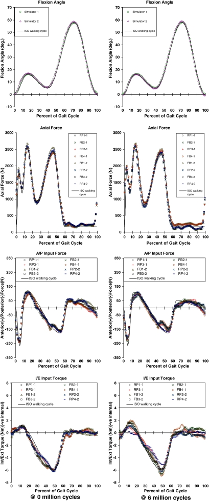
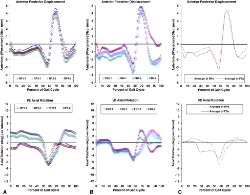
All the input forces and torques, TKA kinematics (flexion, AP motion, and IE rotations), and the soft tissue restraint forces and torques were logged at a rate of 50 samples (of each variable per second) for all specimens, for 20 cycles each time, at over 60 intervals during the test. The results of only two (at the start and the end of the test) were included here (Figs. 1, 2) to verify the input forces and torque had been symmetric across stations/specimens and had followed the desired input waveforms. Samples of the measured kinematics were presented (Fig. 2) to show their general trends and to highlight any major differences in those trends between the two (FB and RP) designs.
Fig. 1.
Measured actuated input variables were averaged over 20 walking cycles at the start and end of the test. The plots are used to illustrate the symmetry between the measured inputs from all stations/specimens and how closely they followed the desired ISO walking cycle waveforms. These were important assumptions in the force control simulation method. AP = anteroposterior; IE = internal/external.
Fig. 2A–C.
Kinematics were averaged over 20 cycles at the start of the test. Top graph in each column shows the anteroposterior displacement, and the bottom shows the internal/external rotation. (A) The first column contains the results for the rotating platform (RP) bearings; (B) the results for the fixed bearings (FB) are shown. (C) The last column shows the averaged four curves from each group and the averages plotted together for comparison.
Before wear testing began, all UHMWPE-bearing inserts were soaked in deionized water for over 2 weeks to stabilize the liquid soaking process as per ISO 14243–1&2. The test was later started only after the increase in weight in any 24-hour period was less than 10% of the total increase in soaking up to that point. To correct for liquid absorption into the UHMWPE, two extra specimens were used as loaded soak controls, immersed in an identical lubricant condition during the wear test, and subjected to axial loading only with an identical waveform as the actual tested specimens. The test was run to 6 million cycles at a simulated walking gait cycle frequency of 1 Hz lubricated with diluted bovine serum lubricant with 20 g/L protein concentration at 37°C.
The wear regions were assessed qualitatively (surface topology observed and photographed) and the wear magnitude was quantitatively measured gravimetrically (by weighing the UHMWPE component to ± 10 μg resolution) according to the standard ISO 14243-2 protocol. All measurements were corrected for liquid absorption based on the loaded soak control specimens. Wear was measured at 100,000 cycles and at 0.5-million cycle intervals up to the end of the 6-million cycle test. The surfaces of all the articulating surfaces were photographed at these stages to record the features of the articulation/wearing regions.
The least square error method was used to calculate the best fit linear regression line through the wear curve (wear versus cycles) for each specimen and thus compute a “wear rate” from its slope. The wear rates for each specimen were tabulated and averaged for each TKA design (FB and RP) for comparison. Based on the averaged data from all four specimens of each type, one combined linear regression line (and thus averaged wear rate from its slope and standard deviation) was also computed to represent all the FB specimens, and one was computed for the RP. These were plotted graphically for comparison, and the scatter of the data was represented by error bars representing the 95% confidence limits at each wear measuring interval. The wear results from each type were statistically compared using a random regression coefficient model to infer the statistical significance of the equality of the wear rates (ie, to estimate a p value to test a null hypothesis of no difference in wear rates) using a PROC MIXED procedure (SAS/STAT software, Version 9.1.3; SAS Institute, Cary, NC).
Results
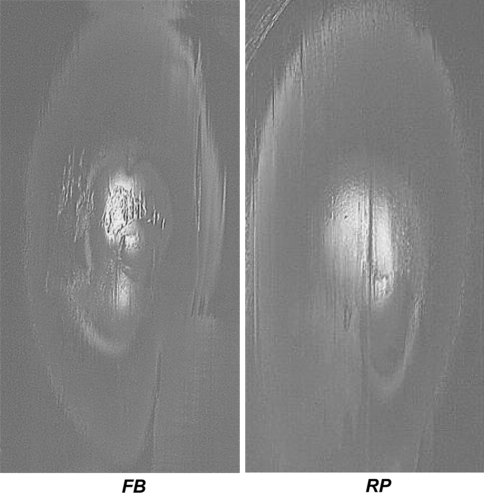
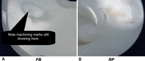
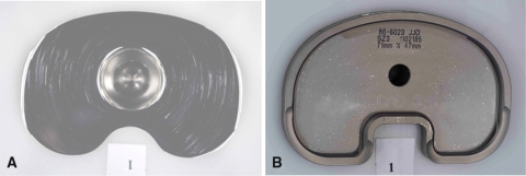
The “qualitative” wear assessment showed no major differences overall in favor of either design. Wear regions on the proximal surface of the bearing inserts were similar with marginally more pitting on the fixed-bearing (Fig. 3). On the distal surface of the inserts (Fig. 4), very minor blemishes could be seen on the fixed bearings with the original machining marks still very visible even at the end of the test. However, on the rotating platform specimens, the machining marks had totally disappeared (or had been polished out) and some pitting could be observed, especially near the central pivot. This means these RP bearing inserts must have rotated relative to the metallic base plates. Superficial arc-shaped surface scratches were also seen on the proximal side of the RP metallic base plates (Fig. 5A). On the other hand, no scratches could be observed on the UHMWPE-supporting surfaces of the FB base plates (Fig. 5B). Several minor surface scratches developed at different stages of the test on all femoral components, which were recorded photographically. One scratch in particular on an FB specimen (DNI 11) was reported to have occurred in the first 1 million cycles, much earlier than any other scratches, and was also relatively deeper.
Fig. 3.
Wear regions on the top surface of the bearings after 5.5 million cycles qualitatively show more top surface wear of the fixed-bearing specimens. This was typical of all stations/specimens. FB = fixed bearing; RP = rotating platform.
Fig. 4A–B.
(A) Distal surface wear after 5.5 million cycles shows more pits on the rotating platform (RP), whereas (B) the machining marks still showed on the fixed bearing (FB). This was also typical of all stations/specimens.
Fig. 5A–B.
Wear regions are shown on the top surface of the metallic tibial base plate near the end of the test. (A) With special lighting and photographic effects, the very shallow surface scratches of the rotating platform specimen base plate are made clear. (B) On the fixed bearing base plate, colors were much more uniform and neither scratches nor any backside motion could be inferred.
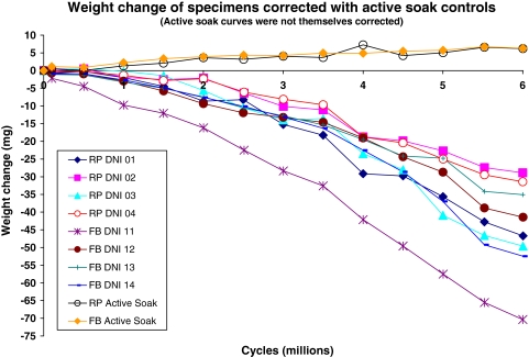
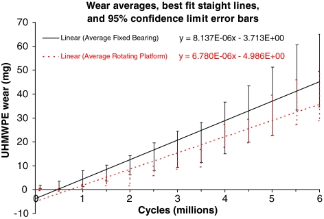
Quantitatively, wear rates for the FB averaged 8.14 ± 2.63 mg/Mc and for the RP averaged 6.78 ± 1.74 mg/Mc (details in Table 1). The weight corrections for liquid absorption with the loaded soak controls (Fig. 6) did not exceed 7 mg overall even toward the end of the test. The individual specimen wear curves showed the usual scatter and some overlap (Fig. 6). The averaged wear rates were statistically similar (p = 0.298) for the two TKA designs (Fig. 7).
Table 1.
Linear corrected weight loss (wear) rates of each specimen
| Specimen | Rotating platform bearings | Fixed bearings | ||||||
|---|---|---|---|---|---|---|---|---|
| DNI 01 | DNI 02 | DNI 03 | DNI 04 | DNI 11 | DNI 12 | DNI 13 | DNI 14 | |
| Wear rate over 6 million cycles (mg/million cycles) | 7.97 | 5.14 | 8.56 | 5.45 | 11.7 | 6.58 | 5.83 | 8.41 |
| Average and standard deviation (mg/million cycles) | 6.78 ± 1.74 | 8.14 ± 2.63 | ||||||
Fig. 6.
Weight loss curves of all eight tested specimens are shown after correction for liquid absorption. Curves are also shown for the loaded soak control specimens to show the amounts that were corrected.
Fig. 7.
Wear curves of each design type (rotating platform versus fixed bearing) were averaged together and compared. The equations shown are the least square error regression lines with a free intercept (not forced through 0). The 95% confidence limits at each stage are shown as error bars and clearly overlap each other.
The logged kinematics showed some differences reflective of the two designs. The RP revealed a slightly more anterior average position of the tibia relative to the femur during stance compared with the FB (Fig. 2). The trends for AP displacement were similar for the two in stance, but the RP showed less range of AP motion in the swing phase (Fig. 2). Being in the swing phase with almost no compressive load, this difference was unlikely to influence wear. Both showed similar trends of IE rotation during stance, but the RP intermittently rotated around a rotationally offset range, shifted by up to ± 2° (Fig. 2). The IE rotations peaked just before toe-off, reaching an average maximum of 7° internal (tibial rotation) in the RP, 1.5 times that of the FB that peaked at approximately 4.5° internally (Fig. 2). Two of the RP specimens were observed during the tests to sometimes show transient dislocations of the UHMWPE insert.
Discussion
Mobile-bearing knee designs have been used clinically for three decades with excellent results. The larger contact area by two separate articulations, lower contact stresses, and separated rotational motions from linear ones have been credited for this success for seemingly reduced wear. The main question was whether this could be verified in a simulation in which all variables were controlled except for the mobility of the bearing.
It may be argued that this study and others were limited by the simulation of only human walking gait without any of the more demanding higher load activities such as stair climbing and squatting. Simulating wear of TKA in walking may be limiting and would need expansion to other activities, but this study provided a comparison under the same inputs. Extra wear caused by activities other than walking must be relatively smaller by virtue of the lower frequency of such activities in daily living. Therefore, wear comparisons with walking are still highly representative of the dominant activity for patients undergoing TKA and currently is the standard activity in knee wear simulators.
Our in vitro study did not address other benefits of the RP design such as rotating laxity, less stress transmitted to the prosthetic bone interface, and tibial self-alignment. On the other hand, there have been some risks reported with mobile bearings such as potentially more backside wear, potential reduced rotation of the bearing insert resulting from intermittent lubricant starvation or edge loading, abrasion resulting from debris, and the rare risk of bearing insert subluxation.
Another limitation of a study such as this is the inability to proportion how much wear had occurred from the backside of the bearing insert. All UHMWPE wear was accounted for in our study by virtue of the gravimetric method used, because it represented the material loss from all surfaces of the insert, including the backside. The RP may have had extra wear as a result of the backside articulation, although this was curvilinear motion, which is usually less severe for wear as crosspath motion. Additionally, this backside articulation, which is of flat-on-flat surfaces, may be prone to extra wear with any third-body abrasive particles such as bone or cement debris in vivo. Our in vitro testing was performed in clean conditions without any such debris deliberately simulated. Backside wear in FBs has also been observed clinically and through in vitro tests. However, it can theoretically only result from micromotion between tightly interlocked modular components, albeit between less polished surfaces, like in this study.
The FB specimen DNI 11, which sustained a relatively deeper scratch on its femoral component earlier than all the others, showed the highest wear in its group and appeared (in Fig. 6) to deviate from the general trend of other FB specimens. It is tempting to speculate that without this single scratch occurring very early and skewing the results of the FB specimens toward a higher average, the FB and RP designs might have shown even closer wear rates.
The magnitudes of wear that resulted from this study were contrasted with the recent results of another laboratory [10] comparing these two implants. The wear of the PFC Sigma FB was reported as 8.8 ± 4.8 mm3/Mc (8.2 ± 4.5 mg/Mc) for intermediate kinematic input and 22.8 ± 5.9 mm3/Mc (21.3 ± 5.5 mg/Mc) for high kinematic input, and for the PFC Sigma RP was 5.2 ± 2.2 mm3/Mc (4.9 ± 2.1 mg/Mc), showing superiority for the RP, especially under high kinematics [10]. The method used in that study was different, a mixture of force and displacement control. No details were specified for the soft tissue restraint simulation for the force control aspects of the simulation, which could have been crucial. Like any study, the results would be sensitive to the inputs actually prescribed to each implant type. Indeed, altering those inputs from previous studies by the same laboratory naturally varied their results [16]. The testing reported here had identical inputs in every way with identical soft tissue simulation.
It is important to note the wear rates for the FB and RP were both very low compared with other implants tested similarly [20]. We concluded the RP bearing design of the PFC did not produce less wear when compared with the very successful [13] FB version of the same implant.
Footnotes
One or more of the authors (HH) has received funding from DePuy Products, Inc, Warsaw, IN.
References
- 1.Biau D, Mullins MM, Judet T, Piriou P. Mobile versus fixed bearing total knee arthroplasty: mid-term comparative clinical results of 216 prostheses. Knee Surg Sports Traumatol Arthrosc. 2006;14:927–933. [DOI] [PubMed]
- 2.Bottlang M, Erne OK, Lacatusu E, Sommers MB, Kessler O. A mobile-bearing knee prosthesis can reduce strain at the proximal tibia. Clin Orthop Relat Res. 2006;447:105–111. [DOI] [PubMed]
- 3.Buechel FF Sr, Buechel FF Jr, Pappas MJ, D’Alessio J. Twenty year evaluation of meniscal bearing and rotating platform knee replacements. Clin Orthop Relat Res. 2001;388:41–50. [DOI] [PubMed]
- 4.Callaghan JJ, Insall JN, Greenwald AS, Dennis DA, Komistek RD, Murray DW, Bourne RB, Rorabeck CH, Dorr LD. Mobile bearing knee replacement: concepts and results. Instr Course Lect. 2001;50:431–449. [PubMed]
- 5.Catani F, Benedetti MG, De Felice R, Buzzi R, Giannini S, Agliettti P. Mobile and fixed bearing total knee prosthesis functional comparison during stair climbing. ClinBiomech. 2003;18:410–418. [DOI] [PubMed]
- 6.Dennis DA, Komistek RD. Kinematics of mobile-bearing total knee arthroplasty. Instr Course Lect. 2005;54:207–220. [PubMed]
- 7.Dixon MC, Brown RR, Parsch D, Scott RD. Modular fixed bearing total knee arthroplasty with retension of the posterior cruciate ligament. A study of patients followed for a minimum of fifteen years. J Bone Joint Surg Am. 2005;87:598–603. [DOI] [PubMed]
- 8.D’Lima DD, Chen PC, Colwell CW Jr. Polyethylene contact stresses, articular congruity, and knee alignment. Clin Orthop Relat Res. 2001;392:232–238. [DOI] [PubMed]
- 9.D’Lima DD, Patil S, Steklov N, Chien S, Colwell C Jr. In vivo knee moments and shear after total knee arthroplasty. J Biomech. 2007;40:S11-S17. [DOI] [PubMed]
- 10.Fisher J, McEwen H, Tipper J, Jennings L, Farrar R, Stone M, Ingham E. Wear-simulation analysis of rotating-platform mobile-bearing knees. Orthopedics. 2006;29(Suppl):S36–41. [PubMed]
- 11.Fukubayashi T, Torzilli PA, Sherman MF, Warren RF. An in-vitro biomechanical evaluation of anterior-posterior motion of the knee. J Bone Joint Surg Am. 1982;64:258–264. [PubMed]
- 12.Gill GS, Joshi AB, Mills DM. Total condylar knee arthroplasty: 16- to 21-year results. Clin Orthop Relat Res. 1999;367:210–215. [DOI] [PubMed]
- 13.Griffin WL, Fehring TK, Pomeroy DL, Gruen TA, Murphy JA. Sterilization and wear-related failure in first- and second-generation press-fit condylar total knee arthroplasty. Clin Orthop Relat Res. 2007;464:16–20. [PubMed]
- 14.Haider H, Walker P, DesJardins J, Blunn G. Effects of patient and surgical alignment variables on kinematics in TKA simulation under force-control. Journal of ASTM International (JAI). 2006;3:1–14.
- 15.Huang CH, Su RY, Lai JH, Hsieh MS. Long-term results of the total condylar knee arthroplasty in Taiwan: a 10 to 15 year follow-up. J Orthop Surg ROC. 1996;13:1–10.
- 16.Jennings LM, Bell CI, Ingham E, Komistek RD, Stone MH, Fisher J. The influence of femoral condylar lift-off on the wear of artificial knee joints. Proc Inst Mech Eng [H]. 2007;221:305–314. [DOI] [PubMed]
- 17.Jones VC, Barton DC, Fitzpatrick DP, Auger DD, Stone MH, Fisher J. An experimental model of tibial counterface polyethylene wear in mobile bearing knees: the influence of design and kinematics. Biomed Mater Eng. 1999;9:189–196. [PubMed]
- 18.Kim YH, Kook HK, Kim JS. Comparison of fixed-bearing and mobile-bearing total knee arthroplasties. Clin Orthop Relat Res. 2001;392:101–115. [DOI] [PubMed]
- 19.Kim YH, Yoon SH, Kim JS. The long term results of simultaneous fixed-bearing and mobile bearing total knee replacements performed in the same patient. J Bone Joint Surg Br. 2007;89:1317–1323. [DOI] [PubMed]
- 20.Knight LA, Pal S, Coleman JC, Bronson F, Haider H, Levine DL, Taylor M, Rullkoetter PJ. Comparison of long-term numerical and experimental total knee replacement wear during simulated gait loading. J Biomech. 2007;40:1550–1558. [DOI] [PubMed]
- 21.Laskin RS. The Genesis total knee prosthesis: a 10-year follow-up study. Clin Orthop Relat Res. 2001;388:95–102. [DOI] [PubMed]
- 22.McEwen HM, Barnett PI, Bell CJ, Farrar R, Auger DD, Stone MH, Fisher J. The influence of design, materials and kinematics on the in vitro wear of total knee replacements. J Biomech. 2005;38:357–365. [DOI] [PubMed]
- 23.Mikosz RP, Andriacchi TP, Andersson GBJ. Model analysis of factors influencing the prediction of muscle forces at the knee. J Orthop Res. 1988;6:205–214. [DOI] [PubMed]
- 24.Morrison JB. The mechanics of the knee joint in relation to normal walking. J Biomech. 1970;3:51–61. [DOI] [PubMed]
- 25.Murray DW, Goodfellow JW, O’Conner JJ. The Oxford medical unicompartmental arthroplasty: a ten year study. J Bone Joint Surg Br. 1998;80:983–989. [DOI] [PubMed]
- 26.Pavone V, Boettner F, Fickert S, Sculco TP. Total condylar knee arthroplasty: a long-term follow-up. Clin Orthop Relat Res. 2001;388:18–25. [DOI] [PubMed]
- 27.Pooley CM, Tabor D. Friction and molecular structure: the behaviour of some thermoplastics. Proc R Soc Lond Ser A. 1972;329:251–274.
- 28.Price AJ, Rees JL, Beard D, Juszczak E, Carter S, White S, De Steiger R, Dodd CAF, Gibbons M, McLardy-Smith P, Goodfellow JW, Murray DW. A mobile-bearing total knee prosthesis compared with a fixed-bearing prosthesis: a multicenter single-blind randomized controlled trial. J Bone Joint Surg Br. 2003;85:62–67. [DOI] [PubMed]
- 29.Ritter MA, Bernard ME, Meding JB, Keating EM, Faris PM, Crites BM. Long-term follow-up of anatomic graduated components posterior cruciate-retaining total knee replacement. Clin Orthop Relat Res. 2001;388:51–57. [DOI] [PubMed]
- 30.Scuderi GR, Insall JN, Windsor RE, Moran MC. Survivorship of cemented knee replacements. J Bone Joint Surg Br. 1989;71:798–803. [DOI] [PubMed]
- 31.Stukenborg-Colsman C, Ostermeier S, Wenger KH, Wirth CJ. Relative motion of a mobile bearing inlay after total knee arthroplasty: dynamic in vitro study. Clin Biomech. 2002;17:49–55. [DOI] [PubMed]
- 32.Taylor S, Walker PS, Perry J, Cannon SR, Woledge R. The forces in the distal femur and the knee during walking and other activities measured by telemetry. J Arthroplasty. 1998;13:428–437. [DOI] [PubMed]
- 33.Walker PS, Haider H. Characterizing the motion of total knee replacements in laboratory tests. Clin Orthop Relat Res. 2003;410:54–68. [DOI] [PubMed]
- 34.Werner F, Foster D, Murray DG. The influence of design on the transmission of torque across knee prostheses. J Bone Joint Surg Am. 1978;60:342–348. [PubMed]


